JP2005297566A - Nozzle provided with nozzle body having heated nozzle body segment and unheated nozzle body segment - Google Patents
Nozzle provided with nozzle body having heated nozzle body segment and unheated nozzle body segment Download PDFInfo
- Publication number
- JP2005297566A JP2005297566A JP2005110897A JP2005110897A JP2005297566A JP 2005297566 A JP2005297566 A JP 2005297566A JP 2005110897 A JP2005110897 A JP 2005110897A JP 2005110897 A JP2005110897 A JP 2005110897A JP 2005297566 A JP2005297566 A JP 2005297566A
- Authority
- JP
- Japan
- Prior art keywords
- nozzle body
- body segment
- nozzle
- injection molding
- molding apparatus
- Prior art date
- Legal status (The legal status is an assumption and is not a legal conclusion. Google has not performed a legal analysis and makes no representation as to the accuracy of the status listed.)
- Pending
Links
- 238000001746 injection moulding Methods 0.000 claims abstract description 114
- 238000011144 upstream manufacturing Methods 0.000 claims description 114
- 239000004020 conductor Substances 0.000 claims description 80
- 239000000155 melt Substances 0.000 claims description 34
- 238000004891 communication Methods 0.000 claims description 12
- 238000010438 heat treatment Methods 0.000 claims description 11
- RYGMFSIKBFXOCR-UHFFFAOYSA-N Copper Chemical compound [Cu] RYGMFSIKBFXOCR-UHFFFAOYSA-N 0.000 claims description 9
- 239000010949 copper Substances 0.000 claims description 9
- 229910052802 copper Inorganic materials 0.000 claims description 9
- 239000012530 fluid Substances 0.000 claims description 9
- 238000005219 brazing Methods 0.000 claims description 7
- 238000003466 welding Methods 0.000 claims description 7
- 239000011248 coating agent Substances 0.000 claims description 6
- 238000000576 coating method Methods 0.000 claims description 6
- 230000004927 fusion Effects 0.000 claims description 6
- 239000000919 ceramic Substances 0.000 claims description 5
- 239000010410 layer Substances 0.000 claims 8
- 239000011247 coating layer Substances 0.000 claims 4
- 230000008878 coupling Effects 0.000 claims 4
- 238000010168 coupling process Methods 0.000 claims 4
- 238000005859 coupling reaction Methods 0.000 claims 4
- 239000000243 solution Substances 0.000 abstract 1
- 239000000463 material Substances 0.000 description 15
- 238000012546 transfer Methods 0.000 description 8
- 230000008859 change Effects 0.000 description 7
- 229910000881 Cu alloy Inorganic materials 0.000 description 6
- 238000009826 distribution Methods 0.000 description 6
- 238000002347 injection Methods 0.000 description 6
- 239000007924 injection Substances 0.000 description 6
- 238000009413 insulation Methods 0.000 description 4
- 238000000034 method Methods 0.000 description 4
- 230000004048 modification Effects 0.000 description 4
- 238000012986 modification Methods 0.000 description 4
- 238000000465 moulding Methods 0.000 description 4
- 238000004519 manufacturing process Methods 0.000 description 3
- 238000003825 pressing Methods 0.000 description 3
- 229910001369 Brass Inorganic materials 0.000 description 2
- 229910000831 Steel Inorganic materials 0.000 description 2
- ATJFFYVFTNAWJD-UHFFFAOYSA-N Tin Chemical compound [Sn] ATJFFYVFTNAWJD-UHFFFAOYSA-N 0.000 description 2
- 229910001315 Tool steel Inorganic materials 0.000 description 2
- 239000010951 brass Substances 0.000 description 2
- 239000012212 insulator Substances 0.000 description 2
- 238000012544 monitoring process Methods 0.000 description 2
- 230000008569 process Effects 0.000 description 2
- 230000005855 radiation Effects 0.000 description 2
- 239000010959 steel Substances 0.000 description 2
- 229910052718 tin Inorganic materials 0.000 description 2
- 229910000984 420 stainless steel Inorganic materials 0.000 description 1
- 229910018072 Al 2 O 3 Inorganic materials 0.000 description 1
- 229910001018 Cast iron Inorganic materials 0.000 description 1
- 229920000106 Liquid crystal polymer Polymers 0.000 description 1
- 239000004977 Liquid-crystal polymers (LCPs) Substances 0.000 description 1
- 229910052581 Si3N4 Inorganic materials 0.000 description 1
- RTAQQCXQSZGOHL-UHFFFAOYSA-N Titanium Chemical compound [Ti] RTAQQCXQSZGOHL-UHFFFAOYSA-N 0.000 description 1
- 230000002411 adverse Effects 0.000 description 1
- 229910052782 aluminium Inorganic materials 0.000 description 1
- XAGFODPZIPBFFR-UHFFFAOYSA-N aluminium Chemical compound [Al] XAGFODPZIPBFFR-UHFFFAOYSA-N 0.000 description 1
- PNEYBMLMFCGWSK-UHFFFAOYSA-N aluminium oxide Inorganic materials [O-2].[O-2].[O-2].[Al+3].[Al+3] PNEYBMLMFCGWSK-UHFFFAOYSA-N 0.000 description 1
- 230000004888 barrier function Effects 0.000 description 1
- DMFGNRRURHSENX-UHFFFAOYSA-N beryllium copper Chemical compound [Be].[Cu] DMFGNRRURHSENX-UHFFFAOYSA-N 0.000 description 1
- 238000005524 ceramic coating Methods 0.000 description 1
- 230000000295 complement effect Effects 0.000 description 1
- 238000010276 construction Methods 0.000 description 1
- 238000007598 dipping method Methods 0.000 description 1
- 229910052751 metal Inorganic materials 0.000 description 1
- 239000002184 metal Substances 0.000 description 1
- 150000002739 metals Chemical class 0.000 description 1
- 239000011347 resin Substances 0.000 description 1
- 229920005989 resin Polymers 0.000 description 1
- 238000007789 sealing Methods 0.000 description 1
- HBMJWWWQQXIZIP-UHFFFAOYSA-N silicon carbide Chemical compound [Si+]#[C-] HBMJWWWQQXIZIP-UHFFFAOYSA-N 0.000 description 1
- HQVNEWCFYHHQES-UHFFFAOYSA-N silicon nitride Chemical compound N12[Si]34N5[Si]62N3[Si]51N64 HQVNEWCFYHHQES-UHFFFAOYSA-N 0.000 description 1
- 238000005476 soldering Methods 0.000 description 1
- 238000005507 spraying Methods 0.000 description 1
- 229910001220 stainless steel Inorganic materials 0.000 description 1
- 239000010935 stainless steel Substances 0.000 description 1
- 239000010936 titanium Substances 0.000 description 1
- 229910052719 titanium Inorganic materials 0.000 description 1
Images


Classifications
-
- B—PERFORMING OPERATIONS; TRANSPORTING
- B29—WORKING OF PLASTICS; WORKING OF SUBSTANCES IN A PLASTIC STATE IN GENERAL
- B29C—SHAPING OR JOINING OF PLASTICS; SHAPING OF MATERIAL IN A PLASTIC STATE, NOT OTHERWISE PROVIDED FOR; AFTER-TREATMENT OF THE SHAPED PRODUCTS, e.g. REPAIRING
- B29C45/00—Injection moulding, i.e. forcing the required volume of moulding material through a nozzle into a closed mould; Apparatus therefor
- B29C45/17—Component parts, details or accessories; Auxiliary operations
- B29C45/26—Moulds
- B29C45/27—Sprue channels ; Runner channels or runner nozzles
- B29C45/2701—Details not specific to hot or cold runner channels
-
- B—PERFORMING OPERATIONS; TRANSPORTING
- B29—WORKING OF PLASTICS; WORKING OF SUBSTANCES IN A PLASTIC STATE IN GENERAL
- B29C—SHAPING OR JOINING OF PLASTICS; SHAPING OF MATERIAL IN A PLASTIC STATE, NOT OTHERWISE PROVIDED FOR; AFTER-TREATMENT OF THE SHAPED PRODUCTS, e.g. REPAIRING
- B29C45/00—Injection moulding, i.e. forcing the required volume of moulding material through a nozzle into a closed mould; Apparatus therefor
- B29C45/17—Component parts, details or accessories; Auxiliary operations
- B29C45/26—Moulds
- B29C45/27—Sprue channels ; Runner channels or runner nozzles
- B29C45/2737—Heating or cooling means therefor
- B29C45/2738—Heating or cooling means therefor specially adapted for manifolds
-
- B—PERFORMING OPERATIONS; TRANSPORTING
- B29—WORKING OF PLASTICS; WORKING OF SUBSTANCES IN A PLASTIC STATE IN GENERAL
- B29C—SHAPING OR JOINING OF PLASTICS; SHAPING OF MATERIAL IN A PLASTIC STATE, NOT OTHERWISE PROVIDED FOR; AFTER-TREATMENT OF THE SHAPED PRODUCTS, e.g. REPAIRING
- B29C45/00—Injection moulding, i.e. forcing the required volume of moulding material through a nozzle into a closed mould; Apparatus therefor
- B29C45/17—Component parts, details or accessories; Auxiliary operations
- B29C45/26—Moulds
- B29C45/27—Sprue channels ; Runner channels or runner nozzles
- B29C45/2701—Details not specific to hot or cold runner channels
- B29C2045/2717—Reconfigurable runner channels
-
- B—PERFORMING OPERATIONS; TRANSPORTING
- B29—WORKING OF PLASTICS; WORKING OF SUBSTANCES IN A PLASTIC STATE IN GENERAL
- B29C—SHAPING OR JOINING OF PLASTICS; SHAPING OF MATERIAL IN A PLASTIC STATE, NOT OTHERWISE PROVIDED FOR; AFTER-TREATMENT OF THE SHAPED PRODUCTS, e.g. REPAIRING
- B29C45/00—Injection moulding, i.e. forcing the required volume of moulding material through a nozzle into a closed mould; Apparatus therefor
- B29C45/17—Component parts, details or accessories; Auxiliary operations
- B29C45/26—Moulds
- B29C45/27—Sprue channels ; Runner channels or runner nozzles
- B29C45/2737—Heating or cooling means therefor
- B29C2045/274—Thermocouples or heat sensors
- B29C2045/2741—Plurality of independent thermocouples or heat sensors
-
- B—PERFORMING OPERATIONS; TRANSPORTING
- B29—WORKING OF PLASTICS; WORKING OF SUBSTANCES IN A PLASTIC STATE IN GENERAL
- B29C—SHAPING OR JOINING OF PLASTICS; SHAPING OF MATERIAL IN A PLASTIC STATE, NOT OTHERWISE PROVIDED FOR; AFTER-TREATMENT OF THE SHAPED PRODUCTS, e.g. REPAIRING
- B29C45/00—Injection moulding, i.e. forcing the required volume of moulding material through a nozzle into a closed mould; Apparatus therefor
- B29C45/17—Component parts, details or accessories; Auxiliary operations
- B29C45/26—Moulds
- B29C45/27—Sprue channels ; Runner channels or runner nozzles
- B29C45/2737—Heating or cooling means therefor
- B29C2045/2754—Plurality of independent heating or cooling means, e.g. independently controlling the heating of several zones of the nozzle
-
- B—PERFORMING OPERATIONS; TRANSPORTING
- B29—WORKING OF PLASTICS; WORKING OF SUBSTANCES IN A PLASTIC STATE IN GENERAL
- B29C—SHAPING OR JOINING OF PLASTICS; SHAPING OF MATERIAL IN A PLASTIC STATE, NOT OTHERWISE PROVIDED FOR; AFTER-TREATMENT OF THE SHAPED PRODUCTS, e.g. REPAIRING
- B29C45/00—Injection moulding, i.e. forcing the required volume of moulding material through a nozzle into a closed mould; Apparatus therefor
- B29C45/17—Component parts, details or accessories; Auxiliary operations
- B29C45/26—Moulds
- B29C45/27—Sprue channels ; Runner channels or runner nozzles
- B29C2045/2766—Heat insulation between nozzle and mould
-
- B—PERFORMING OPERATIONS; TRANSPORTING
- B29—WORKING OF PLASTICS; WORKING OF SUBSTANCES IN A PLASTIC STATE IN GENERAL
- B29C—SHAPING OR JOINING OF PLASTICS; SHAPING OF MATERIAL IN A PLASTIC STATE, NOT OTHERWISE PROVIDED FOR; AFTER-TREATMENT OF THE SHAPED PRODUCTS, e.g. REPAIRING
- B29C45/00—Injection moulding, i.e. forcing the required volume of moulding material through a nozzle into a closed mould; Apparatus therefor
- B29C45/17—Component parts, details or accessories; Auxiliary operations
- B29C45/26—Moulds
- B29C45/27—Sprue channels ; Runner channels or runner nozzles
- B29C2045/2774—The nozzle head or the collar portion and central portion being made of different parts or materials
-
- B—PERFORMING OPERATIONS; TRANSPORTING
- B29—WORKING OF PLASTICS; WORKING OF SUBSTANCES IN A PLASTIC STATE IN GENERAL
- B29C—SHAPING OR JOINING OF PLASTICS; SHAPING OF MATERIAL IN A PLASTIC STATE, NOT OTHERWISE PROVIDED FOR; AFTER-TREATMENT OF THE SHAPED PRODUCTS, e.g. REPAIRING
- B29C45/00—Injection moulding, i.e. forcing the required volume of moulding material through a nozzle into a closed mould; Apparatus therefor
- B29C45/17—Component parts, details or accessories; Auxiliary operations
- B29C45/26—Moulds
- B29C45/27—Sprue channels ; Runner channels or runner nozzles
- B29C2045/2777—Means for controlling heat flow or temperature distribution in the nozzle
-
- B—PERFORMING OPERATIONS; TRANSPORTING
- B29—WORKING OF PLASTICS; WORKING OF SUBSTANCES IN A PLASTIC STATE IN GENERAL
- B29C—SHAPING OR JOINING OF PLASTICS; SHAPING OF MATERIAL IN A PLASTIC STATE, NOT OTHERWISE PROVIDED FOR; AFTER-TREATMENT OF THE SHAPED PRODUCTS, e.g. REPAIRING
- B29C45/00—Injection moulding, i.e. forcing the required volume of moulding material through a nozzle into a closed mould; Apparatus therefor
- B29C45/17—Component parts, details or accessories; Auxiliary operations
- B29C45/26—Moulds
- B29C45/27—Sprue channels ; Runner channels or runner nozzles
- B29C45/28—Closure devices therefor
- B29C45/2806—Closure devices therefor consisting of needle valve systems
Landscapes
- Engineering & Computer Science (AREA)
- Manufacturing & Machinery (AREA)
- Mechanical Engineering (AREA)
- Moulds For Moulding Plastics Or The Like (AREA)
- Injection Moulding Of Plastics Or The Like (AREA)
Abstract
Description
本発明は、全体として、射出成形装置に関し、更に詳細には多数のノズル本体セグメントを含むノズル本体を持つノズルに関する。更に詳細には、本発明は、ノズル本体のノズル本体セグメントのうちの少なくとも一つにヒーターが設けられていない注入ノズルに関する。 The present invention relates generally to an injection molding apparatus, and more particularly to a nozzle having a nozzle body that includes a number of nozzle body segments. More particularly, the present invention relates to an injection nozzle in which at least one of the nozzle body segments of the nozzle body is not provided with a heater.
当該技術分野で良く知られているように、ホットランナー射出成形システムは、加圧された溶融体を入口から一つ又はそれ以上のマニホールド出口まで搬送するためのマニホールドを含む。代表的には、溶融体を複数のモールドキャビティに搬送するため、複数のノズルがマニホールド出口に連結されている。 As is well known in the art, a hot runner injection molding system includes a manifold for conveying a pressurized melt from an inlet to one or more manifold outlets. Typically, a plurality of nozzles are coupled to the manifold outlet to convey the melt to a plurality of mold cavities.
大きな自動車用部品の型成形等の用途では、長さが異なる複数のノズルを単一のマニホールドと連通して使用する必要がある。例えば、注入ノズルに面する表面が不均等なモールドキャビティに溶融体を注入する場合、モールドキャビティに届くようにするため、ノズルの一つの長さを他のノズルよりも長くしなければならない。別の例では、同じモールドに配置されており且つノズルのチップ部分に関する高さ又は深さが異なる別のモールドキャビティに溶融体を同時に注入する場合、長さが異なるノズルが必要とされる。多くの場合にファミリーモールドと呼ばれるこのようなモールドは、同じ又は異なる樹脂又は金属を使用して様々な形状の物品を同時に型成形するための手段を提供する。 In applications such as molding of large automobile parts, it is necessary to use a plurality of nozzles having different lengths in communication with a single manifold. For example, when injecting a melt into a mold cavity where the surface facing the injection nozzle is uneven, one of the nozzles must be longer than the other in order to reach the mold cavity. In another example, nozzles of different lengths are required when simultaneously injecting melt into different mold cavities located in the same mold and having different heights or depths with respect to the tip portion of the nozzle. Such molds, often referred to as family molds, provide a means for simultaneously molding articles of various shapes using the same or different resins or metals.
ノズルの長さを変化させるために、様々な長さの単体ノズルを使用でき、又は単一のノズル本体を含むノズルと二つのノズル本体セグメントを含むノズル本体を持つノズルの組み合わせを使用できる。後者の場合、単一のノズル本体セグメントを別のノズル本体セグメントに連結してノズル本体の全長を変化させ、これによってノズル全体の全長を変化させることができる。 To change the length of the nozzle, single nozzles of varying lengths can be used, or a combination of a nozzle with a single nozzle body and a nozzle body with two nozzle body segments can be used. In the latter case, a single nozzle body segment can be connected to another nozzle body segment to change the overall length of the nozzle body, thereby changing the overall length of the entire nozzle.
溶融体がノズルの溶融体チャンネルを通って移動するときにその温度を維持するために、単一のヒーター又は多数のヒーターのいずれかを使用できる。いずれの場合でも、多くの場合において、マニホールド及びモールドゲートと隣接したノズルの端部で失われる熱は中間区分よりも多い。ノズルの中間区分は、マニホールド又はモールドプレートのいずれの部分とも接触しておらず、及び従って、熱は端部程には急速に失われない。単一のヒーターで加熱される長いノズルでは、中間区分は端部よりも効率的に熱を保持する。その結果、ノズル中間区分の温度は、多くの場合、ノズル又は溶融体チャンネルに沿って単一のヒーターを使用する場合には調節が困難である。かくして、ノズルの中間区分に沿った溶融体の温度は端部における温度よりも高い。この不均一の熱分布は補正や制御が困難である。 Either a single heater or multiple heaters can be used to maintain the temperature as the melt moves through the melt channel of the nozzle. In either case, in many cases, more heat is lost at the end of the nozzle adjacent to the manifold and mold gate than in the middle section. The middle section of the nozzle is not in contact with any part of the manifold or mold plate, and therefore heat is not lost as quickly as the ends. In long nozzles heated by a single heater, the middle section retains heat more efficiently than the ends. As a result, the temperature of the nozzle middle section is often difficult to adjust when using a single heater along the nozzle or melt channel. Thus, the temperature of the melt along the middle section of the nozzle is higher than the temperature at the end. This uneven heat distribution is difficult to correct and control.
溶融体チャンネルに沿った熱分布の不均等は、溶融体が射出成形装置を通って流れるときにその温度の変化が型成形製品の品質に悪影響を及ぼす場合があるため、望ましくない。ノズル及び溶融体チャンネルに沿った不均等な熱分布は、多くは、二つのノズル本体セグメントを含むノズル本体を持つノズルを含む長いノズルを使用する場合に強調される。 Unevenness of the heat distribution along the melt channel is undesirable because the temperature change may adversely affect the quality of the molded product as the melt flows through the injection molding apparatus. The uneven heat distribution along the nozzle and melt channel is often accentuated when using long nozzles including nozzles with nozzle bodies that include two nozzle body segments.
ノズルの長さに沿った不均等な熱分布を補償するために、従来のノズルヒーターを使用する。ノズルヒーターは、ノズル本体に巻き付けた加熱エレメントを含む。加熱エレメントのピッチは、ノズルの不均等な熱損失を補償するために、代表的には、ノズルヘッド及びノズルチップの近くで小さく、ノズル中間区分に沿って長い。この構成の欠点は、従来のヒーターがノズルの全長に沿って熱を加え、中間区分からの熱損失がノズル端部からの熱損失と比較して無視できる程度であるため、ノズルの中間区分に温度スパイクが生じるということである。 Conventional nozzle heaters are used to compensate for uneven heat distribution along the length of the nozzle. The nozzle heater includes a heating element wound around the nozzle body. The pitch of the heating elements is typically small near the nozzle head and nozzle tip and long along the nozzle middle section to compensate for unequal heat loss of the nozzle. The disadvantage of this configuration is that the conventional heater applies heat along the entire length of the nozzle and the heat loss from the middle section is negligible compared to the heat loss from the nozzle end. This means that a temperature spike occurs.
長さを変化させることができる注入ノズルを使用することによって、不均等な表面を持つ部品を型成形するための方法、又は様々な形状を持つ様々な部品を単一のモールドで同時に型成形するための方法を提供する必要がある。更に、可変長ノズルに沿った熱分布を良好に制御し補正する必要がある。更に、長さを容易に調節できる様々な長さの注入ノズルを迅速に且つ更に効率的に製造し、又は注入ノズルを様々な遠隔の位置で製造し組み立てる必要がある。 A method for molding parts with non-uniform surfaces by using injection nozzles that can vary in length, or various parts with different shapes are simultaneously molded in a single mold There is a need to provide a way for. Furthermore, it is necessary to well control and correct the heat distribution along the variable length nozzle. Further, there is a need to quickly and more efficiently manufacture various lengths of injection nozzles whose length can be easily adjusted, or to manufacture and assemble the injection nozzles at various remote locations.
本発明は、マニホールドチャンネルを持つマニホールド及びノズルを含む射出成形装置を提供する。ノズルは、マニホールドと隣接した第1端即ち上流端及びモールドゲートと隣接した第2端即ち下流端を有する。ノズルは、相互係止された少なくとも三つのノズル本体セグメントでできたノズル本体を有する。一つのノズル本体セグメントはノズルの第1端と隣接し、別のノズル本体セグメントがノズルの第2端と隣接している。少なくとも一つの中間ノズル本体セグメントが他の二つのノズル本体セグメント間に配置されている。ノズルの第1及び第2の端部と隣接したノズル本体セグメントは、各々、これらのノズル本体セグメントと接触したノズルヒーターを含む。これらのノズルヒーターは夫々のノズル本体セグメントを直接加熱する。しかしながら、中間ノズル本体セグメントにはヒーターが設けられていない。このように、中間ノズル本体セグメントは、隣接したノズル本体セグメントからの熱伝達によって実質的に間接的に即ち受動的に加熱される。 The present invention provides an injection molding apparatus including a manifold having manifold channels and a nozzle. The nozzle has a first or upstream end adjacent to the manifold and a second or downstream end adjacent to the mold gate. The nozzle has a nozzle body made of at least three nozzle body segments that are interlocked. One nozzle body segment is adjacent to the first end of the nozzle and another nozzle body segment is adjacent to the second end of the nozzle. At least one intermediate nozzle body segment is disposed between the other two nozzle body segments. The nozzle body segments adjacent to the first and second ends of the nozzle each include a nozzle heater in contact with the nozzle body segments. These nozzle heaters heat each nozzle body segment directly. However, the intermediate nozzle body segment is not provided with a heater. In this way, the intermediate nozzle body segment is heated substantially indirectly or passively by heat transfer from adjacent nozzle body segments.
中間ノズル本体セグメントは、螺合、鑞付け、溶接、融着、プレス嵌め係合、又は締まり嵌め係合によって他の二つのノズル本体セグメントと相互係止し、即ち連結されている。一実施形態では、中間ノズル本体セグメントを他の二つのノズル本体セグメントに取り外し自在に取り付けることができ、そのため、型成形されるべき特定の部品に応じて様々な長さの中間ノズル本体セグメントを使用できる。中間ノズル本体セグメントは熱伝導性材料で形成されている。各特定の用途に応じて、中間ノズル本体セグメントの材料の熱伝導率は他の二つのノズル本体セグメントの熱伝導率よりも高いか等しいか或いは僅かに低いのいずれであってもよい。更に、中間ノズル本体セグメントは、この中間ノズル本体セグメントに沿った受動的熱伝達を改善するため即ち高めるために、熱伝導率が中間ノズル本体セグメントの材料よりも高い真鍮、銅、又は銅合金等の材料でできたスリーブやコーティング等の熱伝導性層によって少なくとも部分的に覆われていてもよい。セラミックコーティング等の断熱層を熱伝導性層上で使用してもよい。別の実施形態では、中間ノズル本体セグメントは、熱伝導率がノズル本体セグメント自体よりも高い材料でできたロッド又は任意の他の構造エレメントが完全に又は部分的に埋設されていてもよい。 The intermediate nozzle body segment is interlocked or connected to the other two nozzle body segments by screwing, brazing, welding, fusing, press fit engagement, or interference fit engagement. In one embodiment, the intermediate nozzle body segment can be removably attached to the other two nozzle body segments, thus using different lengths of the intermediate nozzle body segment depending on the particular part to be molded. it can. The intermediate nozzle body segment is formed of a thermally conductive material. Depending on each particular application, the thermal conductivity of the material of the intermediate nozzle body segment may be either higher, equal to or slightly lower than the thermal conductivity of the other two nozzle body segments. In addition, the intermediate nozzle body segment may have a higher thermal conductivity than the material of the intermediate nozzle body segment, such as brass, copper, or copper alloy, to improve or enhance passive heat transfer along the intermediate nozzle body segment. It may be at least partially covered by a thermally conductive layer such as a sleeve or coating made of the above material. A thermal insulation layer such as a ceramic coating may be used on the thermally conductive layer. In another embodiment, the intermediate nozzle body segment may be fully or partially embedded with a rod or any other structural element made of a material that has a higher thermal conductivity than the nozzle body segment itself.
次に、本発明の実施形態を、同様の構造に同じ参照番号が付してある添付図面を参照して更に詳細に説明する。 Embodiments of the present invention will now be described in more detail with reference to the accompanying drawings, in which like structures have like reference numerals.
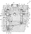
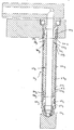
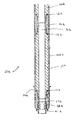
図1を参照すると、射出成形装置10が全体に示してある。射出成形装置10は、マニホールドチャンネル14が通って延びるマニホールド12を含む。型成形可能な材料の溶融体の流れを機械ノズル(図示せず)から受け取って溶融体流れをマニホールド出口18に送出するため、マニホールドブッシュ16がマニホールドチャンネル14の入口に配置されている。マニホールドチャンネル14を通過する溶融体流れを所望温度に維持するため、加熱エレメント(図示せず)がマニホールド12を加熱する。マニホールドの加熱エレメントは埋設等の方法でマニホールド12の表面を取り囲んでいてもよい。マニホールド12は中央位置決めリング15によって所定位置に固定されており、断熱空気空間17が高温のマニホールド12と低温のモールドプレート134との間に形成される。所定幅の別の断熱空気空間37が高温のマニホールド12と低温のクランププレート39との間に配置される。圧力ディスク19がねじ21によって取り付けられており、断熱空気空間37を形成する。各圧力ディスク19は、H13又は420ステンレス鋼等の適当な高強度工具鋼で形成されていてもよく、ねじ21を受け入れるための中央開口部が貫通している。このような圧力ディスクの一例が米国特許第5,125,827号に示されている。同特許に触れたことにより、この特許に開示された内容は本明細書中に含まれたものとする。当業者に明らかなように、他の圧力ディスク又は押圧エレメントを使用してもよい。
Referring to FIG. 1, an
図1は第1ノズル20及び第2ノズル24を示し、これらのノズルの各々は、スプリットモールドプレート34のモールドプレート134及び234に形成された開口部33に配置される。ノズル20及び24は、マニホールド12と、スプリットモールドプレート34のモールドプレート234及び334によって画成された夫々のモールドキャビティ30との間に位置決めされる。ノズル24は、上流ノズル端28及び下流ノズル端32を持つ単一のノズル本体22を含む。溶融体流れを一つのマニホールド出口18から対応するモールドキャビティ30にモールドゲート58を通して送出するため、ノズルチャンネル25がノズル24を通って延びている。ノズル24には、更に、ノズル24を通過するときに溶融体流れを所望温度に維持するのを補助するため、単一のヒーター42が設けられている。このヒーター42には、射出成形装置10の外部に設けられた電源(図示せず)に接続された電気コネクタ44を通して電力が加えられる。ノズル24は、更に、ねじ連結部36によってノズル24の下流端32に保持されたノズルチップ38を含む。
FIG. 1 shows a
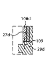
ノズル20は、溶融体流れをマニホールド出口18からモールドキャビティ30まで送出するためのノズル本体23を含み、この本体は、三つのノズル本体セグメント、即ち上流ノズル本体セグメント26、中間ノズル本体セグメント27、及び下流ノズル本体セグメント29を含む。中間ノズル本体セグメント27は、上流ノズル本体セグメント26と下流ノズル本体セグメント29との間に配置されており、ノズル本体23及び従ってノズル20の長さを変化させるのに使用される。中間ノズル本体セグメント27には、これと直接接触するノズルヒーターが設けられていない。上流ノズル本体セグメント26は上流溶融体チャンネル67を有し、中間ノズル本体セグメント27は中間溶融体チャンネル68を有し、下流ノズル本体セグメント29は下流溶融体チャンネル69を有する。これらの溶融体チャンネル67、68、及び69はノズルチャンネル31を集合的に画成し、このノズルチャンネルがマニホールド12のマニホールドチャンネル14と流体連通する。ノズル20と連通したモールドキャビティは、モールドキャビティ30の別の区分であってもよく、溶融体をノズル24を介して受け取るか或いは、別の態様ではノズル24が別のモールドキャビティと連通していてもよい。
The
上流ノズル本体セグメント26は、マニホールド12と隣接した上流端46を含む。上流ノズル本体セグメント26は、電気コネクタ62を通して電力が加えられるノズルヒーター60と接触しており、このヒーターによって直接的に又は積極的に加熱される。
The upstream
一実施形態では、中間ノズル本体セグメント27は上流ノズル本体セグメント26の下流端48に螺合(図示せず)によって連結されており、中間ノズル本体セグメント27の下流端52は下流ノズル本体セグメント29の上流端54に螺合(図示せず)によって連結されている。変形例では、中間ノズル本体セグメント27は上流ノズル本体セグメント26及び下流ノズル本体セグメント29に他の連結手段によって連結されていてもよい。例えば、中間ノズル本体セグメント27は、当業者に既知のように、上流ノズル本体セグメント26及び下流ノズル本体セグメント29に、プレス嵌め係合によって、締まり嵌め係合によって、鑞付けによって、溶接によって、又は融着によって連結できる。中間ノズル本体セグメント27を上流ノズル本体セグメント26及び下流ノズル本体セグメント29に連結するための手段は、ノズル本体セグメント間で相対的移動、例えば摺動が起こらないように連結する。このように、使用中、一つのノズル本体セグメントが熱膨張によって移動すると、これに連結された他のノズル本体セグメントも移動する。
In one embodiment, the intermediate
使用中、マニホールド及びノズル本体セグメントは、両方とも加熱による熱膨張により膨張する。圧力ディスク19は、使用中にマニホールドが膨張したとき、圧力ディスク19がマニホールド12を下方に押圧するように形成されている。かくして、圧力ディスク19は断熱空気空間37の所定の幅を維持する。
In use, both the manifold and nozzle body segments expand due to thermal expansion due to heating. The
ノズル20と同様に、ノズル24もまた、下流ノズル本体セグメント29の下流端56に保持されたノズルチップ38を含む。一実施形態では、ノズルチップ38は下流ノズル本体セグメント29にねじ連結部36を介して連結される。下流ノズル本体セグメント29の下流端56は、モールドゲート58と隣接して配置される。ノズルの熱膨張が生じたとき、各ノズル本体は圧力ディスク19の押圧力によって下方に膨張し、その結果ノズルチップ38がモールドゲート58に対して固定的にシールされる。熱膨張によるマニホールド12の下方への力及び圧力ディスク19の押圧力によっても、マニホールドチャンネル14とノズル溶融体チャンネル25及び31との間がしっかりとシールされる。
Similar to the
下流ノズル本体セグメント29は、電気コネクタ66を通して電力が加えられるノズルヒーター64と接触しており、このヒーターによって直接的に又は積極的に加熱される。電気コネクタ66用のリード(図示せず)は、モールドプレート234のボア11を通して引き出すことができる。別の態様では、電気コネクタ66からのリードは、ノズル20に沿って開口部133を通して射出成形装置10から、電気コネクタ62からのリード(図示せず)と同じ位置で引き出すことができる。このような構成を図2及び図3に示す。図1で明らかなように、上流ノズル本体セグメント26及び下流ノズル本体セグメント29とは異なり、中間ノズル本体セグメント27には別体のノズルヒーターが設けられていない。即ち、中間ノズル本体セグメント27は、別体のノズルヒーターによって直接的に又は積極的に加熱されることがない。というよりはむしろ、中間ノズル本体セグメント27に伝達される熱は、上流ノズル本体セグメント26及び下流ノズル本体セグメント29を実質的に間接的に通過するのである。このように、中間ノズル本体セグメント27は、上流ノズル本体セグメント26及び下流ノズル本体セグメント29からの熱伝達により実質的に受動的に加熱される。
The downstream
一実施形態では、中間ノズル本体セグメント27は熱伝導性材料で形成されている。例えば、中間ノズル本体セグメント27は、工具鋼、鋳鉄、又はステンレス鋼等の任意の鋼で、又はベリリウム−銅によって、又は当業者に明らかな任意の他の熱伝導性材料で形成できる。中間ノズル本体セグメント27を保持し且つ積極的ヒーターを接触させることなく所望量の熱を溶融体に加えるため、中間ノズル本体セグメントは、ノズル全体に関して、又は他のノズル本体セグメントに関してかなりの大きさを備えていなければならない。中間ノズル本体セグメントの大きさは、更に、質量、又は他の等価のパラメータのいずれかに関して表現できる。中間ノズル本体セグメントは、二つの他のノズル本体セグメントの表面接触面積とぴったりと一致する所定の表面接触面積を備えていなければならない。一実施形態では、中間ノズル本体セグメント27の質量又は容積は、ノズル本体の質量又は容積の少なくとも10%である。上流ノズル本体セグメント26及び下流ノズル本体セグメント29もまた、上文中に論じた熱伝導性材料で形成されている。中間ノズル本体セグメント27は、上流ノズル本体セグメント26及び/又は下流ノズル本体セグメント29と同じ、それ以下の、又はそれ以上の熱伝導性を備えていてもよい。
In one embodiment, the intermediate
モールドキャビティ30への入口に設けられたモールドゲート58は、溶融体をモールドキャビティ30に送出できるように選択的に作動できる。ノズル20及び24は熱ゲート式であってもよいしバルブゲート式であってもよい。
A
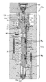
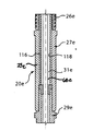
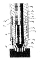
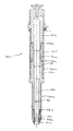
射出成形装置10aの別の実施形態を図2に示す。射出成形装置10aのノズル20aはマニホールド12aの出口18aに連結されている。ノズル20aのノズル本体23aは、上流ノズル本体セグメント26a、中間ノズル本体セグメント27a、及び下流ノズル本体セグメント29aを有する。これらのノズル本体セグメント26a、27a、29aがマニホールド12aのマニホールドチャンネル14aと流体連通したノズルチャンネル31aを画成する。
Another embodiment of the
射出成形装置10aは、図1のスプリットモールドプレート34と同様のスプリットモールドプレート34aを含み、このスプリットモールドプレート34aは、別々のモールドプレート134a、234a、及び334aを含む。モールドキャビティ(図示せず)はプレート334の下流に配置されており、溶融体をノズルチャンネル31aからモールドゲート58aを通して受け取る。モールドゲート58aは、ノズルチャンネル31aを通って延びるバルブピン61によって選択的に作動できる。バルブピン61は、アクチュエータ80によって駆動される。アクチュエータ80は、空気式、液圧式、電気式、又は任意の適当な種類のアクチュエータであってもよい。
The
上流ノズル本体セグメント26aは、上流端46a及び下流端48aを有する。上流ノズル本体セグメント26aの下流端48aは中間ノズル本体セグメント27aの上流端50aに螺合部70によって連結されている。上流ノズル本体セグメント26aの中間ノズル本体セグメント27aへの連結は、下流端48aの表面が上流端50aの表面と接触し、熱を高温の上流ノズル本体セグメント26aから中間ノズル本体セグメント27aに伝達できるように行われる。中間ノズル本体セグメント27aの下流端52aは、下流ノズル本体セグメント29aの上流端54aに螺合部72によって連結されている。同様に、中間ノズル本体セグメント27aの下流ノズル本体セグメント29aへの連結は、下流端52aの表面が上流端54aの表面と接触し、加熱された下流ノズル本体セグメント29aから中間ノズル本体セグメント27aに熱を伝達できるように行われる。中間ノズル本体セグメント27a及び下流ノズル本体セグメント29aの夫々の上流端50a及び54aに突出部102及び104が設けられている。これらの突出部102及び104は、ノズル本体セグメント27a、29aと射出成形装置10aとの連結及び取り外しを容易にするために、工具と係合できるように賦形されている。
The upstream nozzle body segment 26a has an
ノズル20a等の延長ノズルの長さのため、ノズル20aの上流領域でのバルブピン61の小さな不整合によりバルブピン61が変形し、下流のモールドゲート58aのところで大きな不整合を生じる場合がある。かくして、バルブピンガイド82、84、及び86がノズル20aの長さに沿って設けられている。バルブピンガイド82は、上流ノズル本体セグメント26a及び中間ノズル本体セグメント27aによって形成された凹所88に受け入れられる。バルブピンガイド82は、上流ノズル本体セグメント26aと中間ノズル本体セグメント27aとの間のねじ連結部70によって保持される。バルブピンガイド84は、同様に、中間ノズル本体セグメント27aと下流ノズル本体セグメント29aとの間の凹所90に位置決めされ、ねじ連結部72によって保持される。バルブピンガイド86は、ノズルチップ38aと下流ノズル29aの下流端56aとの間に位置決めされ、保持される。下流ノズル本体セグメント29aの下流端56aは、更に、モールドプレート334aと接触してノズル20aをモールドゲート58aと整合するフランジ89を更に含む。
Due to the length of the extended nozzle such as the
バルブピンガイド82、84、及び86の各々には、これらのバルブピンガイド82、84、及び86の各々に溶融体を通すことができると同時にバルブピン61をノズルチャンネル31aの中央に整合した状態に維持し且つモールドゲート58aと整合させる、一つ又はそれ以上のチャンネル(図示せず)が設けられている。適当なバルブピンガイドは、モールド−マスターズ株式会社に譲渡された米国特許出願第10/751,507号に開示されている。同特許出願に触れたことにより、この特許出願に開示された内容は本明細書中に含まれたものとする。
Each of the valve pin guides 82, 84, and 86 allows melt to pass through each of these valve pin guides 82, 84, and 86 while maintaining the valve pin 61 aligned with the center of the
バルブピン61を更に案内し、これをモールドゲート58aと整合した状態に保持するため、ピン支持体92を上流ノズル本体セグメント26aの上流端46aとマニホールド12aとの間に位置決めする。ピン支持体92は、上流端96がマニホールドチャンネル14aと整合し且つこれと流体連通し、下流端98がノズルチャンネル31aと整合し且つこれと流体連通した溶融体チャンネル94を含む。
In order to further guide the valve pin 61 and hold it in alignment with the
ノズル20aは、ノズル本体セグメント26a及び29aの夫々に埋設されたノズルヒーター60a及び64a、並びにこれらのノズルヒーター60a及び64aに夫々連結された電気接続部62a及び66aを含む。この実施形態に示すノズルヒーター60a及び64aはノズル本体セグメントの外面に埋設された螺旋状ヒーターであるが、他の加熱手段を使用してもよい。例えば、ヒーター60a及び64aには、スリーブに(以下に論じるように図10に示すように)埋設した加熱エレメント、ノズル本体セグメントに埋設した加熱ロッド、又は当業者に明らかなカートリッジヒーターが含まれる。ノズル20aは、更に、ノズル本体セグメント26a、27a、及び29aの各々の温度を監視するための、図2にノズル本体セグメント26a、27a、及び29aに埋設した状態で示す熱電対76等の熱電対を含む。制御装置(図示せず)が熱電対76の各々に接続されており、ノズルヒーター60a、64aを制御するのに使用される。
The
カラー74が上流ノズル本体セグメント26aの上流端46aの一部を取り囲み、上流ノズル本体セグメント26a及びかくしてノズル20aをマニホールド12a、ピン支持体92、及びモールドゲート58aに関して位置決めし整合する。カラー74の下面75がスプリットモールドプレート34aの開口部133aに設けられた肩部78に当接し、スリーブをモールドプレート134aに対して配置する。カラー74は、上流ノズル本体セグメント26aからモールドプレート134aへの熱伝達を実質的に阻止する断熱体として作用するために、熱伝導性が低い、例えばチタニウムやセラミック等の材料で形成される。カラー74は、カラー74の下面75とモールドプレート134aの肩部78との間の接触を制限し、かくして上流ノズル本体セグメント26aからの熱損失を減少するためのキャビティ77を含む。カラー74は開口部79を更に含み、この開口部を通って電気コネクタ62a及び66a用のリードが、外部に接続された電源(図示せず)まで延びる。
A
モールドプレート134a、234a、及び334aは、成形プロセス中、ボルト35によって互いに押し付けられ且つ保持される。変形例では、ボルト35は、モールドプレート134a、234a、334a間に形成されたモールドキャビティから型成形された物品を取り出すために外すことができる。例えば、一つのマニホールド12aが、モールドプレート134aと234aとの間及びモールドプレート234aと334aとの間に形成された別々のモールドキャビティに溶融体を同時に注入できる。このような構成では、マニホールド12aの近くに配置されたモールドキャビティと連通するため、短いノズルが設けられる。この構成により、更に多くの又は更に大型の物品を単一のマニホールド12aで製造するのが容易になる。スプリットモールドプレート34aは、当業者に明らかなように、本発明の射出成形装置で様々な形体を形成するモールドプレートの数がこれよりも多くても少なくてもよい。
図2に示すように、中間ノズル本体セグメント27aは別体のヒーターを備えていない。その代わりに、中間ノズル本体セグメント27aは、ヒーター60a及び64aによって夫々加熱される上流ノズル本体セグメント26a及び下流ノズル本体セグメント29aとの接触により、実質的に加熱される。中間ノズル本体セグメント27aは、スプリットモールドプレート34aと直接接触していないため、上流ノズル本体セグメント26a及び下流ノズル本体セグメント29a程には急速に熱を失わない。従って、中間ノズル本体セグメント27aは、上流ノズル本体セグメント26a及び下流ノズル本体セグメント29aから所望温度を維持する上で十分な熱を受け取る。
As shown in FIG. 2, the intermediate nozzle body segment 27a is not provided with a separate heater. Instead, intermediate nozzle body segment 27a is substantially heated by contact with upstream nozzle body segment 26a and downstream
変形例では、中間ノズル本体セグメント27aには、スリーブやコーティング等の外導体層が設けられている。この外導体層により、中間ノズル本体セグメント27aの長さに沿った熱分配の効率を向上する。外導体層は、銅、銅合金、又は任意の他の適当な導体を含んでもよい。一実施形態では、導体層は、導体を中間ノズル本体セグメント27aにスプレーし又は浸漬することによって付けることができる。 In the modification, the intermediate nozzle body segment 27a is provided with an outer conductor layer such as a sleeve or a coating. This outer conductor layer improves the efficiency of heat distribution along the length of the intermediate nozzle body segment 27a. The outer conductor layer may include copper, a copper alloy, or any other suitable conductor. In one embodiment, the conductor layer can be applied by spraying or dipping the conductor into the intermediate nozzle body segment 27a.
作動時においては、溶融体を機械ノズルからマニホールドチャンネル14aに注入する。マニホールドチャンネル14aは、ノズル20aのノズルチャンネル31aを含む複数のノズルチャンネルに溶融体を分配する。溶融体は、ノズルチャンネル31aからモールドキャビティにモールドゲート58aを通して送出される。注入プロセス中、溶融体は、ノズル20aの上流、中間、及び下流のノズル本体セグメント26a、27a、及び29aを通って移動するとき、ほぼ一定の温度に維持される。ノズル本体セグメント26a及び29aの夫々のヒーター60a、64aが独立して制御されるため、ノズル20aはほぼ一定の温度に維持される。ヒーター60a及び64aを独立して制御することにより、更に多くの熱をノズル本体セグメント26a又は29aに加えることができ、これにより、低温のスプリットモールドプレート34aとの接触によって更に多くの熱が失われることになる。中間ノズル本体セグメント27aは上流及び下流のノズル本体セグメント26a及び29aから熱を吸収する。外導体層を使用することにより、熱を中間ノズル本体セグメント27aに沿って更に均等に分配できる。
In operation, the melt is injected from the machine nozzle into the
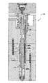
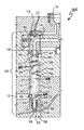
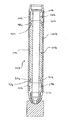
図3を参照すると、射出成形装置10bの別の実施形態が示してある。この実施形態は図2の実施形態と同様であり、ノズル20bのノズル本体23bの中間ノズル本体セグメント27bを取り囲む導体スリーブ106が別の導体層として追加してある。導体スリーブ106は中間ノズル本体セグメント27bの外面108と直接接触している。図2と関連して説明した外導体層と同様に、導体スリーブ106は、上流及び下流のノズル本体セグメント26b、29bから伝達された熱を中間ノズル本体セグメント27bの長さに沿って分配するように機能する。導体スリーブ106は、銅、銅合金、又は任意の他の適当な導体を含んでもよい。
Referring to FIG. 3, another embodiment of an
ノズル20cの別の実施形態を図4に示す。図4のノズル20cは、上流ノズル本体セグメント26c、中間ノズル本体セグメント27c、及び下流ノズル本体セグメント29cを含む。ノズル20cは図3のノズル20bと同様であるが、工具係合突出部110を更に含む。工具係合突出部110は中間ノズル本体セグメント27cに導体スリーブ106cを通してファスナ112によって連結されている。ファスナ112は、図示のようにねじ山を備えていてもよいが、別の適当な種類のファスナであってもよい。所望であれば、工具係合突出部110は、導体スリーブ106cだけに連結されていてもよい。
Another embodiment of the
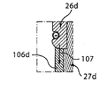
図5を参照すると、ノズル20dの別の実施形態が示してある。ノズル20dは図4のノズル20cと同様であるが、工具係合突出部110dが導体スリーブ106dの外面114に鑞付け又はハンダ付けによって連結されている。更に、工具係合突出部110dは導体スリーブ106dに沿ってほぼ中央に配置されている。これにより、図5Aに矢印107で示すように、熱をノズル本体23dの上流ノズル本体セグメント26dから中間ノズル本体セグメント27dまで間断なく流すことができる。同様に、熱は、図5Bに矢印109で示すように、ノズル本体23dの下流ノズル本体セグメント29dから中間ノズル本体セグメント27dまで間断なく流れる。
Referring to FIG. 5, another embodiment of the
変形例では、コーティング(図示せず)等の断熱層を熱伝導性外層に付ける。例えば、上述の実施形態のうちの任意の実施形態の導体スリーブ106、106c、106dに断熱層を付けることができる。断熱層は、中間ノズル本体から周囲への輻射による熱損失を最少にするように断熱する。断熱層は、断熱を行うために、及び中間ノズル本体から周囲への放射による熱損失をなくすために、熱伝導率が低い材料から形成される。適当な断熱層材料の例が米国仮特許出願第60/460,417号に記載されている。同特許出願に触れたことにより、この特許出願に開示された内容は本明細書中に含まれたものとする。適当な断熱層材料には、アルミナ(Al2O3)、シリコンナイトライド(Si3N4)、シリコンカーバイド(SiC)等のセラミックス、及び例えば液晶ポリマー等の二軸延伸材料が含まれる。断熱層は、セラミックスでコーティングしたエアロメットチューブから形成されていてもよい。
In a variation, a heat insulating layer such as a coating (not shown) is applied to the thermally conductive outer layer. For example, a heat insulating layer can be applied to the
ノズル20eの別の実施形態を図6に示す。この実施形態では、中間ノズル本体27eは、ノズル本体23eのノズルチャンネル31eの中間部分を取り囲む導体層116を含む。導体層116は、ノズルチャンネル31eに挿入したスリーブであってもよく、又は別の態様では、導体層116は、ノズルチャンネル31eの内面118に直接適用されたコーティングであってもよい。導体層は、銅、銅合金、又は任意の適当な導体を含んでもよい。導体層116は、上述の実施形態の導体スリーブ106、106c、106dと同様に機能し、上流及び下流ノズル本体セグメント26e、29eから伝達された熱を中間ノズル本体セグメント27eの長さに沿って分配する。
Another embodiment of the
ノズル20fの別の実施形態を図7に示す。この実施形態では、中間ノズル本体27fは、ノズル本体23fの中間ノズル本体セグメント27fを通して長手方向に配置された導体ロッド120を含む別の導体手段を含む。導体ロッド120は、銅、銅合金、又は任意の適当な導体を含んでもよい。導体ロッド120は、上述の実施形態の導体スリーブ106、106c、106dと同様に機能し、上流及び下流ノズル本体セグメント26f、29fから伝達された熱を中間ノズル本体セグメント27fの長さに沿って分配する。
Another embodiment of the
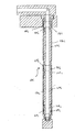
図8は、ノズルヘッド47がマニホールド12にねじ連結部49を介して連結されていることを除き、図1の射出成形装置10と同様の射出成形装置800の別の実施形態の一部を示す。詳細には、上流ノズル本体セグメント26の上流端にマニホールド12と隣接して配置されたノズルヘッド47はマニホールドプラグ40にねじ連結部49を介して連結されている。
FIG. 8 shows part of another embodiment of an
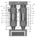
図9は、ファミリーモールドで使用する本発明の一実施形態を示す。ファミリーモールドは、多構成要素製品の一つ以上の構成要素を同じモールドの別のモールドキャビティで同時に型成形するモールドである。図9は、二つのマニホールドチャンネル914が貫通したマニホールド912を含む射出成形システム900を示す。機械ノズル(図示せず)から型成形可能材料の溶融体の流れを受け入れるため、及び溶融体流れをマニホールド出口918に送出するため、二つのマニホールドブッシュ916が各マニホールドチャンネル914の入口に配置されている。加熱エレメント(図示せず)がマニホールド912を加熱し、マニホールドチャンネル914を通過する溶融体流れを所望温度に維持する。マニホールドの加熱エレメントは、マニホールド912の表面に埋設されているか或いは他の態様でマニホールドを取り囲んでいる。
FIG. 9 shows one embodiment of the present invention for use in a family mold. A family mold is a mold that simultaneously molds one or more components of a multi-component product in another mold cavity of the same mold. FIG. 9 shows an
射出成形装置900は、第1ノズル920、第2ノズル922、第3ノズル924、及び第4ノズル926の4つのノズルを有する。各ノズル920、922、924、及び926は、三つのノズル本体セグメントでできたノズル本体921、923、925、及び927を夫々含む。第1ノズル本体921は、上流ノズル本体セグメント928、中間ノズル本体セグメント929、及び下流ノズル本体セグメント930を含む。第2ノズル本体923は、上流ノズル本体セグメント928、中間ノズル本体セグメント931、及び下流ノズル本体セグメント930を含む。第3ノズル本体925は、上流ノズル本体セグメント928、中間ノズル本体セグメント932、及び下流ノズル本体セグメント930を含む。最後に、第4ノズル本体927は、上流ノズル本体セグメント928、中間ノズル本体セグメント933、及び下流ノズル本体セグメント930を含む。図示のように、各ノズル本体の中間ノズル本体セグメント929、931、932、及び933は長さL1、L2、L3、及びL4が異なり、そのためノズル本体921、923、925、及び927の夫々の長さが変化する。
The
各ノズルのノズル本体セグメントは、溶融体流れをマニホールド出口918から様々なモールドキャビティに送出するノズルチャンネル934を画成する。詳細には、第1ノズル920の溶融体チャンネル934は溶融体流れを第1モールドキャビティ935に送出する。第2ノズル922の溶融体チャンネル934は溶融体流れを第2モールドキャビティ936に送出する。最後に、第3ノズル924及び第4ノズル926の溶融体チャンネル931は溶融体流れを第3モールドキャビティ937に送出する。各ノズル920、922、924、及び926のノズルヘッド938はマニホールド912と隣接している。ノズル920のノズルチップ939は第1モールドキャビティ935に続くモールドゲート940と隣接している。ノズル922のノズルチップ939は第2モールドキャビティ936に続くモールドゲート941と隣接している。ノズル924及び926のノズルチップ939は第3モールドキャビティ937に続くモールドゲート942及び943と夫々隣接している。この実施形態では、上流ノズル本体セグメント928は、各々、電気コネクタ944によって電力が加えられるノズルヒーター(図示せず)と接触しており、このヒーターによって直接的に即ち積極的に加熱される。同様に、加熱ノズル本体セグメント930は、電気コネクタ946によって電力が加えられるノズルヒーター(図示せず)と各々接触しており、このヒーターによって直接的に即ち積極的に加熱される。
The nozzle body segment of each nozzle defines a
中間ノズル本体セグメント929、931、932、及び933は、ノズル本体921、923、925、及び927の長さを変化させることによってノズル920、922、924、及び926の長さを変化させるのに使用される。中間ノズル本体セグメント929、931、932、及び933には、これらの中間セグメントと直接接触するノズルヒーターが設けられていない。即ち、中間ノズル本体セグメント929、931、932、及び933は、別体のノズルヒーターによって直接的に即ち積極的に加熱されるのではない。というよりはむしろ、熱は、上流及び下流のノズル本体セグメント928及び930を通して中間ノズル本体セグメント929、931、932、及び933に実質的に間接的に伝達されるのである。このように、中間ノズル本体セグメント929、931、932、及び933は、上流及び下流のノズル本体セグメント928及び930からの熱伝達により実質的に受動的に加熱される。
Intermediate
図1に関して上文中に説明した実施形態と同様に、上流ノズル本体セグメント928は中間ノズル本体セグメント929、931、932、及び933の夫々に螺合、プレス嵌め係合、締まり嵌め係合、鑞付け、溶接、又は融着によって連結できる。同様に、下流ノズル本体セグメント930は中間ノズル本体セグメント929、931、932、及び933の夫々に螺合、プレス嵌め係合、締まり嵌め係合、鑞付け、溶接、又は融着によって連結できる。中間ノズル本体セグメントを上流及び下流のノズル本体セグメントに連結するための手段は、これらのノズル本体セグメント間で相対的移動、例えば摺動が生じないように連結する。このように、使用中、一つのノズル本体セグメントが熱膨張によって移動すると、これに連結された他方のノズル本体セグメントもまた移動する。
Similar to the embodiment described above with respect to FIG. 1, the upstream
図10は、本発明の射出成形装置1000の別の実施形態を示す。装置1000は、マニホールド1012とモールドキャビティ1030との間に位置決めされた二つのノズル1020を含む。これらのノズル1020は、溶融体流れをマニホールドチャンネル1014からモールドキャビティ1030まで送出するため、三つのノズル本体セグメント、即ち上流ノズル本体セグメント1026、中間ノズル本体セグメント1027、及び下流ノズル本体セグメント1029で形成されたノズル本体1023を各々含む。上述の実施形態と同様に、中間ノズル本体セグメント1027は、ノズル本体1023の長さ及び従って、ノズル1020の長さを変化させるため、様々な長さを備えていてもよい。中間ノズル本体セグメント1027には、更に、この中間セグメントと直接接触したノズルヒーターが設けられていない。中間ノズル本体セグメント1027は、上流ノズル本体セグメント1026と下流ノズル本体セグメント1029との間に配置される。ノズル本体セグメント1026、1027、及び1029が、マニホールド1012のマニホールドチャンネル1014と流体連通したノズルチャンネル1031を画成する。
FIG. 10 shows another embodiment of the
装置1000は、各ノズルの周囲に配置されており且つノズルヒーター(図示せず)に接続されたヒータースリーブ1033を含む。一実施形態では、ノズルヒーターは各スリーブ1033にその長さに沿って埋設されている。電気コネクタ1062がノズルヒーターに接続されている。ノズル1020及び/又はスリーブ1022は、更に、ノズル本体セグメント1026、1027、及び1029の各々の温度を監視し、ノズルヒーターを制御するための熱電対(図示せず)を含んでもよい。スリーブ1022は、ノズルヒーターからの熱がスリーブ1033を通って下側のノズル1020に伝達されるように、好ましくは、熱伝導率が比較的高い材料で形成される。スリーブ1033の各々には、このスリーブ1033が中間ノズル本体セグメント1027と直接接触しないように、中間ノズル本体セグメント1027と隣接して切り欠き1035を有する。切り欠き1035は、各スリーブ1033とセグメント1027との間に空隙を形成する。空気は、熱がヒータースリーブ1033から中間ノズル本体セグメント1027に伝達しないようにする断熱体として役立つ。
The
ノズル20gの別の実施形態を図11に示す。この実施形態では、ノズル20gはノズル本体23gを有する。このノズル本体は、中間ノズル本体セグメント27g、及び上流ノズル本体セグメント26g及び下流ノズル本体セグメント29gとして使用される二つの標準的ノズル本体セグメントを含む。上流ノズル本体セグメント26g及び下流ノズル本体セグメント29gは、これらのノズル本体セグメントに埋め込まれたヒーター60g及び64gによって加熱される。中間ノズル本体セグメント27gの上流端50gは上流ノズル本体セグメント26gの下流端48gに螺合部70gによって連結され、中間ノズル本体セグメント27gの下流端52gは下流ノズル本体セグメント29gの上流端54gに螺合部72gによって連結される。中間ノズル本体セグメント27gの長さは、任意の所望の全長を備えたノズル20gを形成するように選択される。
Another embodiment of the nozzle 20g is shown in FIG. In this embodiment, the nozzle 20g has a nozzle body 23g. The nozzle body includes an intermediate nozzle body segment 27g and two standard nozzle body segments used as an upstream nozzle body segment 26g and a downstream nozzle body segment 29g. The upstream nozzle body segment 26g and the downstream nozzle body segment 29g are heated by heaters 60g and 64g embedded in these nozzle body segments. The upstream end 50g of the intermediate nozzle body segment 27g is connected to the downstream end 48g of the upstream nozzle body segment 26g by a screwing
保持スリーブ105gが上流ノズル本体セグメント26g及び下流ノズル本体セグメント29gの各々の周囲に配置されている。これらの保持スリーブは、上流ノズル本体セグメント26g及び下流ノズル本体セグメント29gに近い熱膨張率を持つように形成される。導体スリーブ106gが中間ノズル本体セグメント27gの周囲に配置されており、各保持スリーブ105gに肩部インターフェースによって連結されている。肩部インターフェースは保持スリーブ105gの各々に設けられた肩部111gによって形成され、これらの肩部111gは、導体スリーブ106gの各端に設けられた肩部113gと相補的に形成されている。この実施形態では、肩部111g及び肩部113gは、肩部係合部のところで導体スリーブ106gが保持スリーブ105gから半径方向内方に配置されるように形成される。導体スリーブ106gは、銅、銅合金、錫、又は他の適当な導体から形成される。保持スリーブ105gは、鋼、錫、又は他の適当な導体から形成される。 A holding sleeve 105g is disposed around each of the upstream nozzle body segment 26g and the downstream nozzle body segment 29g. These holding sleeves are formed to have a coefficient of thermal expansion close to that of the upstream nozzle body segment 26g and the downstream nozzle body segment 29g. A conductor sleeve 106g is disposed around the intermediate nozzle body segment 27g and is connected to each holding sleeve 105g by a shoulder interface. The shoulder interface is formed by shoulders 111g provided on each of the holding sleeves 105g, and these shoulders 111g are formed in a complementary manner with the shoulders 113g provided at each end of the conductor sleeve 106g. In this embodiment, the shoulder 111g and the shoulder 113g are formed such that the conductor sleeve 106g is disposed radially inward from the holding sleeve 105g at the shoulder engaging portion. Conductor sleeve 106g is formed from copper, copper alloy, tin, or other suitable conductor. The retaining sleeve 105g is formed from steel, tin, or other suitable conductor.
保持スリーブ105gと導体スリーブ106gとの肩部係合部は、ノズル本体23gに関する導体スリーブ106gの熱膨張を制御するように機能する。例えば、中間ノズル本体27gの熱膨張率が導体スリーブ106gよりも低い実施形態では、導体スリーブ106gが熱膨張により中間ノズル本体27gから分離する可能性を肩部係合部で制限するように、保持スリーブ105gを中間ノズル本体27gと同じ熱膨張率で膨張するように形成してもよい。 The shoulder engaging portion between the holding sleeve 105g and the conductor sleeve 106g functions to control the thermal expansion of the conductor sleeve 106g with respect to the nozzle body 23g. For example, in an embodiment in which the thermal expansion coefficient of the intermediate nozzle body 27g is lower than that of the conductor sleeve 106g, the shoulder engagement portion restricts the possibility that the conductor sleeve 106g separates from the intermediate nozzle body 27g due to thermal expansion. The sleeve 105g may be formed so as to expand at the same thermal expansion coefficient as the intermediate nozzle body 27g.
ノズル20gは、相互交換可能な標準的セグメントを上流ノズル本体セグメント26g及び下流ノズル本体セグメント29gに使用するモジュール式の構造を有する。この実施形態では、螺合部70g及び螺合部72gは、両方とも、中間ノズル本体セグメント27gが雄ねじ表面を提供し、上流ノズル本体セグメント26g及び下流ノズル本体セグメント29gの両方が雌ねじ表面を提供するように形成されている。
Nozzle 20g has a modular construction that uses interchangeable standard segments for upstream nozzle body segment 26g and downstream nozzle body segment 29g. In this embodiment, both the threaded
ノズル20gの下流部分を図12に詳細に示す。下流ノズル本体セグメント29gは二つの雌ねじ表面101g、103gを含む。上流ねじ表面101gは、螺合部72gの一部を形成し、下流ねじ表面103gは、ノズルチップ38gを下流ノズル本体セグメント29gに連結するチップリテーナ41gと係合する。下流ノズル本体セグメント29gは熱電対81gを更に含む。熱電対(図示せず)をノズル20gの長さに沿った様々な位置に配置できるように、図示のように多数の熱電対チューブ81gを設けてもよい。 The downstream portion of the nozzle 20g is shown in detail in FIG. The downstream nozzle body segment 29g includes two internal thread surfaces 101g, 103g. The upstream thread surface 101g forms part of the threaded portion 72g, and the downstream thread surface 103g engages a tip retainer 41g that connects the nozzle tip 38g to the downstream nozzle body segment 29g. The downstream nozzle body segment 29g further includes a thermocouple 81g. A number of thermocouple tubes 81g may be provided as shown so that thermocouples (not shown) can be placed at various positions along the length of the nozzle 20g.
ノズル20hの別の実施形態を図13に示す。ノズル20hは、標準的上流ノズル本体セグメント26h、中間ノズル本体セグメント27h、標準的下流ノズル本体セグメント29h、及び埋設されたヒーター60h及び64hを備えたノズル本体23hを含む点で、図11のノズル20gと同様である。しかしながら、この実施形態では、導体スリーブ106hが中間ノズル本体セグメント27hの周囲に配置されており、一対の保持スリーブ105hの各々に当接する。上流ノズル本体セグメント26h及び下流ノズル本体セグメント29hの各々からの熱は、夫々の保持スリーブ105hの各々に伝達できる。これらの保持スリーブ105hと導体スリーブ106hとの衝合により、導体スリーブ106hの熱膨張率が保持スリーブ105hと異なる場合、導体スリーブ106hを保持するのに摩擦力が使用される。更に、導体スリーブ106hと保持スリーブ105hとの間の接触により、上流ノズル本体セグメント26h及び下流ノズル本体セグメント29hから導体スリーブ106hへの間断ない熱の流れが生じる。導体スリーブ106hは、更に、熱を中間本体部分27hに伝達する。
Another embodiment of the
ノズル20iの別の実施形態を図14に示す。ノズル20iは図11のノズル20gと同様であるが、二つの追加の本体セグメントを含む。ノズル20iは、上流ノズル本体セグメント26i及び下流ノズル本体セグメント29iとして使用される加熱される標準的セグメントに加え、一対の中間ノズル本体セグメント27i、一対の導体スリーブ106i、追加の加熱される標準的ノズル本体セグメント99i、及び多数の保持スリーブ105iを含む。上流ノズル本体セグメント26i、下流ノズル本体セグメント29i、及び標準的ノズル本体セグメント99iの各々は、埋設されたヒーター60i、64i、及び65iの夫々によって加熱される。標準的ノズル本体セグメント99iは、対をなした中間ノズル本体セグメント27i間に配置されており、対をなした中間ノズル本体セグメント27iの各々に螺合部によって連結される。この実施形態では、標準的ノズル本体セグメント99iは、ノズル20iを容易に延長できるように、上流ノズル本体セグメント26i又は下流ノズル本体セグメント29iと相互交換自在であるように形成される。導体スリーブ106i及び保持スリーブ105iは、肩部係合部によって連結された状態で示してあるが、衝合連結等の任意のインターフェースを含んでもよいということは理解されるべきである。 Another embodiment of the nozzle 20i is shown in FIG. Nozzle 20i is similar to nozzle 20g of FIG. 11, but includes two additional body segments. The nozzle 20i includes a pair of intermediate nozzle body segments 27i, a pair of conductor sleeves 106i, an additional heated standard nozzle in addition to the heated standard segments used as the upstream nozzle body segment 26i and the downstream nozzle body segment 29i. It includes a body segment 99i and a number of retaining sleeves 105i. Each of the upstream nozzle body segment 26i, the downstream nozzle body segment 29i, and the standard nozzle body segment 99i is heated by respective embedded heaters 60i, 64i, and 65i. The standard nozzle body segment 99i is disposed between the pair of intermediate nozzle body segments 27i and is connected to each of the pair of intermediate nozzle body segments 27i by screwing portions. In this embodiment, the standard nozzle body segment 99i is formed to be interchangeable with the upstream nozzle body segment 26i or the downstream nozzle body segment 29i so that the nozzle 20i can be easily extended. The conductor sleeve 106i and the retaining sleeve 105i are shown connected by a shoulder engaging portion, but it should be understood that any interface such as an abutting connection may be included.
別の実施形態では、図15に下流部分を示すノズル20kは、マニホールドプラグ40k、加熱される標準的上流ノズル本体セグメント26k、加熱される標準的下流ノズル本体セグメント29k、中間ノズル本体セグメント27k、導体スリーブ106k、及び導体ワッシャ115kを含む。ノズル20kは、チップリテーナ41kによってノズル本体セグメント29k内に保持されたノズルチップ38kを更に含む。しかしながら、ノズル20kは、ノズル20iとは異なり、加熱されるセグメント26k及び29k上に配置される保持スリーブを含まない。導体スリーブ106kは、隣接したノズル本体セグメント26k及び29kと衝合連結部によってインターフェースを形成し、これらの間の圧縮力によって所定位置に保持される。
In another embodiment, the
導体ワッシャ115kは、隣接したノズル本体セグメント間に挟まれる。例えば、導体ワッシャ115kは、ノズル本体セグメント26kの上流端と隣接したマニホールドプラグ40kとの間、及びノズル本体セグメント26kの下流端と隣接した中間ノズル本体セグメント27kとの間に挟まれる。別の導体ワッシャ115kがノズル本体セグメント29kの上流端54kと隣接した中間ノズル本体セグメント27kとの間に挟まれる。
The conductor washer 115k is sandwiched between adjacent nozzle body segments. For example, the conductor washer 115k is sandwiched between the upstream end of the
導体ワッシャ115kは、隣接したセグメントを連結するときに圧縮されるように、これらの隣接したセグメントよりも剛性が低い材料で形成されていてもよい。この圧縮性により、熱膨張中にワッシャが最初に潰れるため、隣接したセグメントの各々を保護する。ワッシャ115kの圧縮性により、更に、各ワッシャ115kと隣接した部品との間の接触を増大し、従って、隣接した部品間の熱伝達を良好にすると同時に隣接した部品を互いい対して適正にシールできる。例えば、ノズル本体セグメント26k及び27kを互いに対してシールして連続した溶融体チャンネル31kを形成し、ワッシャ115kは、セグメント26kの下流端とセグメント27kの上流部分の肩部との間で圧縮される。
The conductor washer 115k may be formed of a material that is less rigid than these adjacent segments so that they are compressed when connecting adjacent segments. This compressibility protects each of the adjacent segments as the washer is first collapsed during thermal expansion. The compressibility of the washers 115k further increases the contact between each washer 115k and adjacent components, thus providing good heat transfer between adjacent components and at the same time properly sealing adjacent components together. it can. For example,
導体ワッシャ115kの材料は、高度の熱伝導性を持つように選択できる。例えば、導体ワッシャ115kは、銅、真鍮、アルミニウム、又は当業者に既知の任意の他の材料から形成できる。隣接したセグメントは、組み立て後に導体ワッシャ115kを圧縮し又は潰すように設計できる。更に、導体ワッシャ115kは、隣接したセグメントを連結するときに圧縮される導電性ばねワッシャであってもよい。 The material of the conductor washer 115k can be selected to have a high degree of thermal conductivity. For example, the conductor washer 115k can be formed from copper, brass, aluminum, or any other material known to those skilled in the art. Adjacent segments can be designed to compress or collapse the conductor washer 115k after assembly. Further, the conductive washer 115k may be a conductive spring washer that is compressed when connecting adjacent segments.
図16及び図17は別の実施形態のノズル20mを示す。図8のノズル20と同様に、ノズル20mは、マニホールドプラグ40m、上流ノズル本体セグメント26m、中間ノズル本体セグメント27m、及び下流ノズル本体セグメント29mを含み、連続した溶融体チャンネル31mを形成する。熱伝導性を向上するため、導体スリーブ106m、126m、及び導体ワッシャ115m、125mもまた設けられている。中間ノズル本体セグメント27mは、直径が第1直径D1から小径の第2直径D2まで変化する中間溶融体チャンネル68mを含む。
16 and 17 show another embodiment of a
ノズル20mでは、中間ノズル本体セグメント27mの外径は、溶融体チャンネル68mが直径D1を有する部分で大きく、溶融体チャンネル68mが直径D2を有する部分で小さい。そのため、導体スリーブ106m及び126mは、ノズル本体セグメント27mの直径に合わせて直径が異なる。更に、導体ワッシャ115m及び125mは、ノズル20mの長さに沿った外径の変化に合わせて直径が異なる。ノズル20mの外径が異なることにより、上流ノズル本体セグメント26m及び下流ノズル本体セグメント29mは同じ標準的な部品ではない。というよりはむしろ、下流ノズル本体セグメント29mは上流ノズル本体セグメント26mよりも小さく、その下流部分がノズル20mの外径と一致する。
In the
別の実施形態のノズル20nを図18に示す。ノズル20nは、マニホールドプラグ40n、上流ノズル本体セグメント26n、中間ノズル本体セグメント27n、下流ノズル本体セグメント及びノズルチップ38nを含み、連続した溶融体チャンネル31nを形成する。チップ38nは下流ノズル本体セグメント29nにチップリテーナ41nによって連結されている。ノズル本体セグメント間の熱伝達を向上するため、導体ワッシャ115n及び導体スリーブ106nもまた設けられている。ノズル20nは、中間ノズル本体セグメント27nが、直径が第1直径D1から小径の第2直径D2まで変化する中間溶融体チャンネル68mを含むという点で上文中に説明したノズル20mと同様である。しかしながら、ノズル本体セグメント27nの外径はその長さに沿って変化せず、そのためノズル20nの外径はその長さに沿って変化しない。このような形体により、部品を標準化できる。例えば、上流ノズル本体セグメント26n及び下流ノズル本体セグメント29nは、同じ加熱されたノズル本体セグメントである。同様に、全ての導体ワッシャ115nが標準的な大きさであり、導体スリーブ106nが標準的な大きさである。
Another embodiment of a nozzle 20n is shown in FIG. The nozzle 20n includes a
本発明の多くの特徴及び利点が詳細な説明から明らかであり、及びかくして添付の特許請求の範囲は、本発明の真の精神及び範囲内の本発明のこのような特徴及び利点の全てを含もうとするものである。更に、当業者は多くの変形及び変更を容易に思いつくであろうから、本発明をここに例示し且つ説明したのと全く同じ構造及び作動に限定しようとするものではなく、従って、全ての適当な変形例及び等価物が本発明の範疇に含まれる。 Many features and advantages of the invention will be apparent from the detailed description, and thus the appended claims will cover all such features and advantages of the invention within the true spirit and scope of the invention. It is something to be attempted. Further, since many variations and modifications will readily occur to those skilled in the art, the present invention is not intended to be limited to the exact structure and operation illustrated and described herein, and thus is Various modifications and equivalents are included in the scope of the present invention.
Claims (68)
マニホールドチャンネルを持つマニホールド、
ノズル本体を持つノズルであって、前記ノズル本体は、前記マニホールドと隣接し且つ第1溶融体チャンネルを持つ第1ノズル本体セグメント、第2溶融体チャンネルを持つ第2ノズル本体セグメント、及び前記モールドゲートと隣接し且つ第3溶融体チャンネルを持つ第3ノズル本体セグメントを含み、前記第2ノズル本体セグメントは、前記マニホールドチャンネルと流体連通したノズルチャンネルを前記第1、第2、及び第3溶融体チャンネルが集合的に画成するように、前記第1ノズル本体セグメントと前記第3ノズル本体セグメントとの間に配置されている、ノズル、及び
前記第2ノズル本体セグメントを前記第3ノズル本体セグメントに連結するための手段を備え、前記第1及び第3ノズル本体セグメントは加熱され、前記第2ノズル本体セグメントはこのセグメントと接触したヒーターを備えていない、射出成形装置。 In injection molding equipment with a mold gate,
Manifold with manifold channel,
A nozzle having a nozzle body, the nozzle body adjacent to the manifold and having a first melt channel, a second nozzle body segment having a second melt channel, and the mold gate A third nozzle body segment adjacent to and having a third melt channel, wherein the second nozzle body segment includes a nozzle channel in fluid communication with the manifold channel and the first, second, and third melt channels. Are arranged between the first nozzle body segment and the third nozzle body segment, and the second nozzle body segment is connected to the third nozzle body segment. Means for heating, wherein the first and third nozzle body segments are heated and the second An injection molding device in which the nozzle body segment does not have a heater in contact with the segment.
前記第1ノズル本体セグメントに連結された第1熱電対、及び
前記第3ノズル本体セグメントに連結された第2熱電対を更に含む、射出成形装置。 The injection molding apparatus according to claim 1,
An injection molding apparatus further comprising: a first thermocouple connected to the first nozzle body segment; and a second thermocouple connected to the third nozzle body segment.
前記第2ノズル本体セグメントに連結された第3熱電対を更に含む、射出成形装置。 The injection molding apparatus according to claim 6,
The injection molding apparatus further comprising a third thermocouple coupled to the second nozzle body segment.
マニホールドチャンネルを持つマニホールド、
ノズル本体を持つノズルであって、前記ノズル本体は、上流溶融体チャンネルを持つ上流ノズル本体セグメント、中間溶融体チャンネルを持つ中間ノズル本体セグメント、及び下流溶融体チャンネルを持つ下流ノズル本体セグメントを含み、前記中間ノズル本体セグメントは、前記マニホールドチャンネルと流体連通したノズルチャンネルを前記上流溶融体チャンネル、中間溶融体チャンネル、及び下流溶融体チャンネルが集合的に画成するように、前記上流ノズル本体セグメントと前記下流ノズル本体セグメントとの間に配置されている、ノズル、及び
前記中間ノズル本体セグメントを前記下流ノズル本体セグメントに連結するための手段を備え、前記上流及び下流ノズル本体セグメントは加熱され、前記中間ノズル本体セグメントはノズルヒーターを実質的に備えていない、射出成形装置。 In injection molding equipment,
Manifold with manifold channel,
A nozzle having a nozzle body, the nozzle body including an upstream nozzle body segment having an upstream melt channel, an intermediate nozzle body segment having an intermediate melt channel, and a downstream nozzle body segment having a downstream melt channel; The intermediate nozzle body segment includes the upstream nozzle body segment and the upstream nozzle body segment such that the upstream melt channel, the intermediate melt channel, and the downstream melt channel collectively define a nozzle channel in fluid communication with the manifold channel. A nozzle disposed between a downstream nozzle body segment, and means for connecting the intermediate nozzle body segment to the downstream nozzle body segment, wherein the upstream and downstream nozzle body segments are heated and the intermediate nozzle Nose segment Injection molding equipment that does not substantially include a heater.
前記上流ノズル本体セグメントに連結された第1熱電対、及び
前記下流ノズル本体セグメントに連結された第2熱電対を更に含む、射出成形装置。 The injection molding device according to claim 14,
The injection molding apparatus further comprising: a first thermocouple connected to the upstream nozzle body segment; and a second thermocouple connected to the downstream nozzle body segment.
前記中間ノズル本体セグメントに連結された第3熱電対を更に含む、射出成形装置。 The injection molding apparatus according to claim 21,
The injection molding apparatus further comprising a third thermocouple coupled to the intermediate nozzle body segment.
ノズル本体であって、
前記マニホールドと隣接して配置され、第1溶融体チャンネルを持つ第1ノズル本体セグメント、
第2溶融体チャンネルを持つ第2ノズル本体セグメント、及び
前記モールドゲートと隣接して配置され、第3溶融体チャンネルを持つ第3ノズル本体セグメントを含み、前記第2ノズル本体セグメントは、前記第1、第2、及び第3溶融体チャンネルがノズル溶融体チャンネルを集合的に画成するように、前記第1ノズル本体セグメントと前記第3ノズル本体セグメントとの間に配置されている、ノズル本体、及び
前記第2ノズル本体セグメントと前記第3ノズル本体セグメントとを連結するための手段を備え、前記第1及び第3ノズル本体セグメントは加熱され、前記第2ノズル本体セグメントはノズルヒーターを実質的に備えていない、射出成形装置。 In a nozzle for use in an injection molding apparatus having a manifold and a mold gate,
A nozzle body,
A first nozzle body segment disposed adjacent to the manifold and having a first melt channel;
A second nozzle body segment having a second melt channel; and a third nozzle body segment disposed adjacent to the mold gate and having a third melt channel, wherein the second nozzle body segment includes the first nozzle body segment A nozzle body disposed between the first nozzle body segment and the third nozzle body segment such that the second and third melt channels collectively define the nozzle melt channel; And means for connecting the second nozzle body segment and the third nozzle body segment, wherein the first and third nozzle body segments are heated, and the second nozzle body segment substantially includes a nozzle heater. An injection molding device that is not equipped.
マニホールドチャンネルを持つマニホールド、及び
ノズル本体を持つノズルであって、前記ノズル本体は、前記マニホールドと隣接し且つ第1溶融体チャンネルを持つ第1ノズル本体セグメント、第2溶融体チャンネルを持つ第2ノズル本体セグメント、及び前記モールドゲートと隣接し且つ第3溶融体チャンネルを持つ第3ノズル本体セグメントを含み、前記第2ノズル本体セグメントは、ノズル溶融体チャンネルを前記第1、第2、及び第3溶融体チャンネルが集合的に画成するように、前記第1ノズル本体セグメントと前記第3ノズル本体セグメントとの間に配置されている、ノズルを備え、
前記第1及び第3ノズル本体セグメントは加熱され、前記第2ノズル本体セグメントはこのセグメントと接触したヒーターを備えておらず、前記第2ノズル本体セグメントは前記第3ノズル本体セグメントに連結されている、射出成形装置。 In injection molding equipment with a mold gate,
A manifold having a manifold channel and a nozzle having a nozzle body, wherein the nozzle body is adjacent to the manifold and has a first nozzle body segment having a first melt channel and a second nozzle having a second melt channel. A body segment, and a third nozzle body segment adjacent to the mold gate and having a third melt channel, the second nozzle body segment including the nozzle melt channel in the first, second, and third melts. A nozzle disposed between the first nozzle body segment and the third nozzle body segment such that body channels are collectively defined;
The first and third nozzle body segments are heated, the second nozzle body segment does not have a heater in contact with the segment, and the second nozzle body segment is connected to the third nozzle body segment. Injection molding equipment.
マニホールドチャンネルを持つマニホールド、及び
ノズル本体を持つノズルであって、前記ノズル本体は、上流溶融体チャンネルを持つ上流ノズル本体セグメント、中間溶融体チャンネルを持つ中間ノズル本体セグメント、及び下流溶融体チャンネルを持つ下流ノズル本体セグメントを含み、前記中間ノズル本体セグメントは、ノズル溶融体チャンネルを前記上流溶融体チャンネル、前記中間溶融体チャンネル、及び前記下流溶融体チャンネルが集合的に画成するように、前記上流ノズル本体セグメントと前記下流ノズル本体セグメントとの間に配置されている、ノズルを備え、
前記上流及び下流ノズル本体セグメントは加熱され、前記中間ノズル本体セグメントはノズルヒーターを実質的に備えておらず、前記中間ノズル本体セグメントは前記下流ノズル本体セグメントに連結されている、射出成形装置。 In injection molding equipment,
A manifold having a manifold channel and a nozzle having a nozzle body, the nozzle body having an upstream nozzle body segment having an upstream melt channel, an intermediate nozzle body segment having an intermediate melt channel, and a downstream melt channel A downstream nozzle body segment, wherein the intermediate nozzle body segment defines a nozzle melt channel such that the upstream melt channel, the intermediate melt channel, and the downstream melt channel collectively define the nozzle melt channel. A nozzle disposed between a body segment and the downstream nozzle body segment;
An injection molding apparatus wherein the upstream and downstream nozzle body segments are heated, the intermediate nozzle body segment is substantially free of nozzle heaters, and the intermediate nozzle body segment is connected to the downstream nozzle body segment.
ノズル本体であって、
前記マニホールドと隣接して配置され且つ第1溶融体チャンネルを持つ第1ノズル本体セグメント、
第2溶融体チャンネルを持つ第2ノズル本体セグメント、及び
前記モールドゲートと隣接して配置され且つ第3溶融体チャンネルを持つ第3ノズル本体セグメントを有し、前記第2ノズル本体セグメントは、前記第1、第2、及び第3溶融体チャンネルがノズルチャンネルを集合的に画成するように、前記第1ノズル本体セグメントと前記第3ノズル本体セグメントとの間に配置されている、ノズル本体を備え、
前記第1及び第3ノズル本体セグメントは加熱され、前記第2ノズル本体セグメントはノズルヒーターを備えておらず、前記第2ノズル本体セグメントは前記第3ノズル本体セグメントに連結されている、射出成形装置。 In a nozzle for use in an injection molding apparatus having a manifold and a mold gate,
A nozzle body,
A first nozzle body segment disposed adjacent to the manifold and having a first melt channel;
A second nozzle body segment having a second melt channel; and a third nozzle body segment disposed adjacent to the mold gate and having a third melt channel, wherein the second nozzle body segment is A nozzle body disposed between the first nozzle body segment and the third nozzle body segment such that the first, second and third melt channels collectively define the nozzle channel; ,
The injection molding apparatus, wherein the first and third nozzle body segments are heated, the second nozzle body segment is not provided with a nozzle heater, and the second nozzle body segment is connected to the third nozzle body segment .
マニホールドチャンネルを持つマニホールド、及び
ノズル本体を持つノズルであって、前記ノズル本体は、上流溶融体チャンネルを持つ上流ノズル本体セグメント、中間溶融体チャンネルを持つ中間ノズル本体セグメント、及び下流溶融体チャンネルを持つ下流ノズル本体セグメントを含み、前記中間ノズル本体セグメントは、ノズルチャンネルを前記上流溶融体チャンネル、前記中間溶融体チャンネル、及び前記下流溶融体チャンネルが集合的に画成するように、前記上流ノズル本体セグメントと前記下流ノズル本体セグメントとの間に配置されている、ノズルを備え、
前記第1及び第3ノズル本体セグメントは加熱され、前記中間ノズル本体セグメントは実質的に受動的に加熱され、前記中間ノズル本体セグメントは前記下流ノズル本体セグメントに連結されている、射出成形装置。 In injection molding equipment,
A manifold having a manifold channel and a nozzle having a nozzle body, the nozzle body having an upstream nozzle body segment having an upstream melt channel, an intermediate nozzle body segment having an intermediate melt channel, and a downstream melt channel And includes an upstream nozzle body segment such that the upstream melt channel, the intermediate melt channel, and the downstream melt channel collectively define a nozzle channel. And a nozzle disposed between the downstream nozzle body segment and
An injection molding apparatus, wherein the first and third nozzle body segments are heated, the intermediate nozzle body segment is heated substantially passively, and the intermediate nozzle body segment is connected to the downstream nozzle body segment.
マニホールドチャンネルを持つマニホールド、
ノズル本体を持つノズルであって、前記ノズル本体は、上流溶融体チャンネルを持つ上流ノズル本体セグメント、中間溶融体チャンネルを持つ中間ノズル本体セグメント、及び下流溶融体チャンネルを持つ下流ノズル本体セグメントを含み、前記中間ノズル本体セグメントは、ノズル溶融体チャンネルを前記上流溶融体チャンネル、前記中間溶融体チャンネル、及び前記下流溶融体チャンネルが集合的に画成するように、前記上流ノズル本体セグメントと前記下流ノズル本体セグメントとの間に配置されている、ノズル、
前記ノズルの外面の周囲に配置されたヒータースリーブであって、前記上流ノズル本体セグメント及び前記下流ノズル本体セグメントと接触しており且つ切り欠きが実質的に前記中間ノズル本体セグメントの長さに沿って形成されている、ヒータースリーブ、及び
前記ヒータースリーブと接触したノズルヒーターを備えた射出成形装置。 In injection molding equipment,
Manifold with manifold channel,
A nozzle having a nozzle body, the nozzle body including an upstream nozzle body segment having an upstream melt channel, an intermediate nozzle body segment having an intermediate melt channel, and a downstream nozzle body segment having a downstream melt channel; The intermediate nozzle body segment includes the upstream nozzle body segment and the downstream nozzle body such that a nozzle melt channel is collectively defined by the upstream melt channel, the intermediate melt channel, and the downstream melt channel. A nozzle, located between the segments,
A heater sleeve disposed around an outer surface of the nozzle, in contact with the upstream nozzle body segment and the downstream nozzle body segment and having a notch substantially along the length of the intermediate nozzle body segment; An injection molding apparatus comprising: a formed heater sleeve; and a nozzle heater in contact with the heater sleeve.
前記ノズル溶融体チャンネル内に配置されたバルブピン、及び
前記バルブピンと駆動係合して配置されたアクチュエータを更に含む、射出成形装置。 The injection molding apparatus according to claim 1,
An injection molding apparatus further comprising: a valve pin disposed in the nozzle melt channel; and an actuator disposed in driving engagement with the valve pin.
前記第1ノズル本体セグメントと前記第2ノズル本体セグメントとの間に配置された第1バルブピンガイド、及び
前記第3ノズル本体セグメントの下流に配置された第2バルブピンガイドを更に含む、射出成形装置。 The injection molding device according to claim 36,
An injection molding apparatus, further comprising: a first valve pin guide disposed between the first nozzle body segment and the second nozzle body segment; and a second valve pin guide disposed downstream of the third nozzle body segment.
前記第2ノズル本体セグメントと前記第3ノズル本体セグメントとの間に配置された第3バルブピンガイドを更に含む、射出成形装置。 The injection molding apparatus according to claim 37,
An injection molding apparatus further comprising a third valve pin guide disposed between the second nozzle body segment and the third nozzle body segment.
前記ノズル溶融体チャンネルに配置されたバルブピン、及び
前記バルブピンと駆動係合して配置されたアクチュエータを更に含む、射出成形装置。 The injection molding device according to claim 14,
An injection molding apparatus further comprising a valve pin disposed in the nozzle melt channel, and an actuator disposed in driving engagement with the valve pin.
前記上流ノズル本体セグメントと前記中間ノズル本体セグメントとの間に配置された第1バルブピンガイド、及び
前記下流ノズル本体セグメントの下流に配置された第2バルブピンガイドを更に含む、射出成形装置。 The injection molding apparatus according to claim 39,
An injection molding apparatus, further comprising: a first valve pin guide disposed between the upstream nozzle body segment and the intermediate nozzle body segment; and a second valve pin guide disposed downstream of the downstream nozzle body segment.
前記中間ノズル本体セグメントと前記下流ノズル本体セグメントとの間に配置された第3バルブピンガイドを更に含む、射出成形装置。 The injection molding apparatus according to claim 40,
An injection molding apparatus further comprising a third valve pin guide disposed between the intermediate nozzle body segment and the downstream nozzle body segment.
前記ノズル溶融体チャンネルに配置されたバルブピン、
前記第1ノズル本体セグメントと前記第2ノズル本体セグメントとの間に配置された第1バルブピンガイド、及び
前記第3ノズル本体セグメントの下流に配置された第2バルブピンガイドを更に含む、ノズル。 The nozzle of claim 27.
A valve pin disposed in the nozzle melt channel;
The nozzle further comprising: a first valve pin guide disposed between the first nozzle body segment and the second nozzle body segment; and a second valve pin guide disposed downstream of the third nozzle body segment.
前記第2ノズル本体セグメントと前記第3ノズル本体セグメントとの間に配置された第3バルブピンガイドを更に含む、ノズル。 43. A nozzle according to claim 42.
The nozzle further comprising a third valve pin guide disposed between the second nozzle body segment and the third nozzle body segment.
前記第1ノズル本体セグメントの周囲に配置された第1モールドプレート、及び
前記第2ノズル本体セグメントの周囲に配置された第2モールドプレートを更に含む、射出成形装置。 The injection molding apparatus according to claim 1,
An injection molding apparatus further comprising: a first mold plate disposed around the first nozzle body segment; and a second mold plate disposed around the second nozzle body segment.
前記第3ノズル本体セグメントの下流に配置された第3モールドプレートを更に含み、前記第2モールドプレート及び前記第3モールドプレートがモールドキャビティを画成する、射出成形装置。 The injection molding device according to claim 44,
An injection molding apparatus further comprising a third mold plate disposed downstream of the third nozzle body segment, wherein the second mold plate and the third mold plate define a mold cavity.
前記上流ノズル本体セグメントの周囲に配置された第1モールドプレート、及び
前記中間ノズル本体セグメントの周囲に配置された第2モールドプレートを更に含む、射出成形装置。 The injection molding device according to claim 14,
An injection molding apparatus, further comprising: a first mold plate disposed around the upstream nozzle body segment; and a second mold plate disposed around the intermediate nozzle body segment.
前記下流ノズル本体セグメントの下流に配置された第3モールドプレートを更に含む、射出成形装置。 The injection molding device according to claim 48,
An injection molding apparatus further comprising a third mold plate disposed downstream of the downstream nozzle body segment.
マニホールド、及び
前記マニホールドと複数の前記モールドゲートとの間に配置された複数のノズルであって、前記複数のノズルのうちの少なくとも一つのノズルが、前記マニホールドと隣接した第1ノズル本体セグメント、第2ノズル本体セグメント、及び複数の前記モールドゲートのうちの一つのモールドゲートと隣接した第3ノズル本体セグメントを含むノズル本体を有し、前記第2ノズル本体セグメントは、前記第1ノズル本体セグメントと前記第3ノズル本体セグメントとの間に配置され、複数の前記ノズルのうちの少なくとも二つのノズルは長さが異なる、複数のノズルを有し、
前記少なくとも一つのノズルの前記第1及び第3のノズル本体セグメントが加熱され、前記第2ノズル本体セグメントはこのセグメントと接触したヒーターを備えていない、射出成形装置。 In injection molding equipment with multiple mold gates,
A plurality of nozzles disposed between the manifold and the plurality of mold gates, wherein at least one of the plurality of nozzles is adjacent to the manifold, A nozzle body including a second nozzle body segment and a third nozzle body segment adjacent to one mold gate of the plurality of mold gates, wherein the second nozzle body segment includes the first nozzle body segment and the first nozzle body segment; Between the third nozzle body segment, and at least two nozzles of the plurality of nozzles have a plurality of nozzles having different lengths;
An injection molding apparatus wherein the first and third nozzle body segments of the at least one nozzle are heated and the second nozzle body segment does not include a heater in contact with the segment.
マニホールド、及び
前記マニホールドと複数の前記モールドゲートとの間に配置された複数のノズルであって、前記複数のノズルのうちの少なくとも一つのノズルが、前記マニホールドと隣接した第1ノズル本体セグメント、第2ノズル本体セグメント、及び前記モールドゲートと隣接した第3ノズル本体セグメントを含むノズル本体を有し、前記第2ノズル本体セグメントは、前記第1ノズル本体セグメントと前記第3ノズル本体セグメントとの間に配置され、複数の前記ノズルのうちの少なくとも二つが別のモールドキャビティと流体連通している、複数のノズルを有し、
前記少なくとも一つのノズルの前記第1及び第3のノズル本体セグメントが加熱され、前記第2ノズル本体セグメントはこのセグメントと接触したヒーターを備えていない、射出成形装置。 In an injection molding apparatus having a plurality of mold gates and a plurality of mold cavities,
A plurality of nozzles disposed between the manifold and the plurality of mold gates, wherein at least one of the plurality of nozzles is adjacent to the manifold, A nozzle body including a second nozzle body segment and a third nozzle body segment adjacent to the mold gate, wherein the second nozzle body segment is between the first nozzle body segment and the third nozzle body segment. A plurality of nozzles disposed, wherein at least two of the plurality of nozzles are in fluid communication with another mold cavity;
An injection molding apparatus wherein the first and third nozzle body segments of the at least one nozzle are heated and the second nozzle body segment does not include a heater in contact with the segment.
前記第1ノズル本体セグメントに連結された第1熱電対、及び
前記第3ノズル本体セグメントに連結された第2熱電対を更に含む、ノズル。 The nozzle of claim 27.
The nozzle further comprising: a first thermocouple coupled to the first nozzle body segment; and a second thermocouple coupled to the third nozzle body segment.
前記第2ノズル本体セグメントに連結された第3熱電対を更に含む、ノズル。 57. The nozzle of claim 56.
The nozzle further comprising a third thermocouple coupled to the second nozzle body segment.
前記第1及び第3のノズル本体セグメントに供給される熱を制御するための、前記第1及び第2の熱電対と関連した制御装置を更に含む、ノズル。 57. The nozzle of claim 56.
The nozzle further comprising a controller associated with the first and second thermocouples for controlling heat supplied to the first and third nozzle body segments.
前記第1及び第3のノズル本体セグメントに供給される熱を制御するための、前記第1及び第2の熱電対と関連した制御装置を更に含む、射出成形装置。 The injection molding apparatus according to claim 6,
An injection molding apparatus further comprising a controller associated with the first and second thermocouples for controlling heat supplied to the first and third nozzle body segments.
前記上流及び下流のノズル本体セグメントに供給される熱を制御するための、前記第1及び第2の熱電対と関連した制御装置を更に含む、射出成形装置。 The injection molding apparatus according to claim 21,
An injection molding apparatus further comprising a controller associated with the first and second thermocouples for controlling heat supplied to the upstream and downstream nozzle body segments.
前記第1ノズル本体セグメントの少なくとも一部を覆う第1保持スリーブ、及び
前記第3ノズル本体セグメントの少なくとも一部を覆う第2保持スリーブを更に含む、射出成形装置。 In the injection molding device according to claim 5,
An injection molding apparatus further comprising: a first holding sleeve that covers at least a part of the first nozzle body segment; and a second holding sleeve that covers at least a part of the third nozzle body segment.
Applications Claiming Priority (2)
| Application Number | Priority Date | Filing Date | Title |
|---|---|---|---|
| US55997704P | 2004-04-07 | 2004-04-07 | |
| US61899604P | 2004-10-18 | 2004-10-18 |
Publications (2)
| Publication Number | Publication Date |
|---|---|
| JP2005297566A true JP2005297566A (en) | 2005-10-27 |
| JP2005297566A5 JP2005297566A5 (en) | 2008-05-22 |
Family
ID=35329674
Family Applications (1)
| Application Number | Title | Priority Date | Filing Date |
|---|---|---|---|
| JP2005110897A Pending JP2005297566A (en) | 2004-04-07 | 2005-04-07 | Nozzle provided with nozzle body having heated nozzle body segment and unheated nozzle body segment |
Country Status (2)
| Country | Link |
|---|---|
| US (1) | US7462030B2 (en) |
| JP (1) | JP2005297566A (en) |
Cited By (4)
| Publication number | Priority date | Publication date | Assignee | Title |
|---|---|---|---|---|
| JP2009539640A (en) * | 2006-06-08 | 2009-11-19 | ギュンター・ハイスカナルテヒニク・ゲゼルシヤフト・ミト・ベシユレンクテル・ハフツング | Injection molding nozzles, especially hot runner nozzles for installation on injection molding tools |
| JP2009539641A (en) * | 2006-06-08 | 2009-11-19 | ギュンター・ハイスカナルテヒニク・ゲゼルシヤフト・ミト・ベシユレンクテル・ハフツング | Injection molding nozzles, especially hot channel nozzles, for placement in injection molds |
| KR101005275B1 (en) | 2008-07-08 | 2011-01-04 | 유도실업주식회사 | The tube for Hwater fixing to be set at hot runner system for injection transforning mold |
| KR20220048308A (en) * | 2020-10-12 | 2022-04-19 | 주식회사 유도 | Hot runner system for double injection |
Families Citing this family (17)
| Publication number | Priority date | Publication date | Assignee | Title |
|---|---|---|---|---|
| US7160100B2 (en) | 2004-01-06 | 2007-01-09 | Mold-Masters Limited | Injection molding apparatus having an elongated nozzle incorporating multiple nozzle bodies in tandem |
| CA2482254A1 (en) * | 2004-04-07 | 2005-10-07 | Mold-Masters Limited | Modular injection nozzle having a thermal barrier |
| DE602006015565D1 (en) * | 2005-05-19 | 2010-09-02 | Mold Masters Ltd | Injection molding nozzle with a thermally conductive sleeve and method for its production |
| US7462031B2 (en) * | 2005-11-25 | 2008-12-09 | Mold-Masters (2007) Limited | Injection molding nozzle with recessed terminal |
| US7810549B2 (en) * | 2007-01-05 | 2010-10-12 | Ford Global Technologies, Llc | Adaptive and universal hot runner manifold for die casting |
| WO2011008583A1 (en) * | 2009-07-17 | 2011-01-20 | Husky Injection Molding Systems Ltd | Modular manifold system |
| US20130309349A1 (en) * | 2011-02-09 | 2013-11-21 | Husky Injection Molding Systems Ltd. | Mold-Tool System Having Heat-Transfer Obstruction |
| WO2014085008A1 (en) * | 2012-11-27 | 2014-06-05 | Husky Injection Molding Systems Ltd. | Molding material distribution device |
| US10485633B2 (en) * | 2013-02-14 | 2019-11-26 | Tulsa Dental Products Llc | Molded dental root canal filling points/cones and process of making same |
| WO2014133702A1 (en) * | 2013-02-27 | 2014-09-04 | Husky Injection Molding Systems Ltd. | Hot runner and components thereof with a melt conditioning zone |
| RS59249B1 (en) * | 2014-06-20 | 2019-10-31 | Live Tech S R L | Injection molding system for a fat-containing product |
| ITUB20154577A1 (en) * | 2015-10-12 | 2017-04-12 | Inglass Spa | INJECTOR FOR PLASTIC INJECTION MOLDING EQUIPMENT AND INJECTION MOLDING EQUIPMENT |
| DE102016203995A1 (en) * | 2016-03-10 | 2017-09-14 | Otto Männer Innovation GmbH | Hot runner system and associated nozzle heaters |
| CN107813466A (en) * | 2017-12-05 | 2018-03-20 | 东泰精密注塑(天津)有限公司 | A kind of glue mouth separation equipment |
| DE102019106975A1 (en) * | 2019-03-19 | 2020-09-24 | EWIKON Heißkanalsysteme GmbH | Hot or cold runner device for an injection molding tool with an exchangeable deflection and distribution insert |
| PT3991941T (en) * | 2020-10-27 | 2023-11-21 | Mold Masters 2007 Ltd | Valve pin plate injection molding apparatus |
| US11931937B2 (en) * | 2021-05-07 | 2024-03-19 | The Gillette Company Llc | Method and system for molding an article |
Citations (5)
| Publication number | Priority date | Publication date | Assignee | Title |
|---|---|---|---|---|
| JPH02210668A (en) * | 1989-02-10 | 1990-08-22 | Nec Corp | Magnetic tape controller |
| JPH038512U (en) * | 1989-06-14 | 1991-01-28 | ||
| JP2002011764A (en) * | 2000-06-28 | 2002-01-15 | Mitsubishi Materials Corp | Molding method and valve gate type mold apparatus used therein |
| JP2002331552A (en) * | 2001-05-09 | 2002-11-19 | Mitsubishi Materials Corp | Valve gate type die device |
| JP2004148551A (en) * | 2002-10-28 | 2004-05-27 | Mitsubishi Materials Corp | Valve gate type mold assembly |
Family Cites Families (43)
| Publication number | Priority date | Publication date | Assignee | Title |
|---|---|---|---|---|
| AU452137B2 (en) | 1971-09-24 | 1974-08-29 | Bischoff Chemical Corporation | Injection nozzle of adjustable length |
| US3812323A (en) * | 1972-11-03 | 1974-05-21 | Ford Motor Co | Electrical heating bands for a feeding system |
| US3843295A (en) * | 1973-05-24 | 1974-10-22 | Bischoff Chemical Corp | Injection molding machine with adjustable nozzle length means |
| NL7804984A (en) * | 1978-05-09 | 1979-11-13 | Beek Ter Hengelo Bv | INTERNAL HEATABLE MOUTH WITH A DIVIDABLE HOUSING AND A DIVIDABLE CORE. |
| JPS59142124A (en) * | 1983-02-02 | 1984-08-15 | Shigeru Tsutsumi | Hot tip bushing for synthetic resin injection molder |
| CA1206311A (en) * | 1983-09-12 | 1986-06-24 | Jobst U. Gellert | Injection molding system having an insulation sleeve |
| DE3560864D1 (en) * | 1984-02-06 | 1987-12-10 | Bernard Stauber | Transfer nozzle in a heating channel mould |
| JPS61134218A (en) * | 1984-12-05 | 1986-06-21 | Shigeru Tsutsumi | Temperature control and display device of hot runner in injection molding system of thermoplastic synthetic resin |
| DE8620956U1 (en) | 1986-08-05 | 1986-11-27 | Jetform Heißkanalnormalien und Zubehör GmbH, 7255 Rutesheim | Device for electrical heating of hot runner nozzles |
| JPS63202418A (en) | 1987-02-18 | 1988-08-22 | Fuji Kikai Seizo Kk | Hot runner type injection molding method and apparatus |
| FR2625133B1 (en) * | 1987-12-24 | 1990-09-21 | Delta Projet | MOLDING NOZZLE FOR PLASTIC MATERIAL INJECTION |
| CA1265909A (en) * | 1988-02-16 | 1990-02-20 | Jobst Ulrich Gellert | Injection molding heated gate insert and method |
| CA1266359A (en) * | 1988-04-13 | 1990-03-06 | Harald H. Schmidt | Injection molding system with nozzles in tandem |
| CA1261575A (en) * | 1988-04-13 | 1989-09-26 | Jobst U. Gellert | Injection molding valve gating one of two nozzles in tandem |
| US4892474A (en) * | 1989-02-21 | 1990-01-09 | Gellert Jobst U | Profiled plate heaters for injection molding nozzles |
| CA2008171C (en) * | 1990-01-19 | 1997-05-20 | Jobst Ulrich Gellert | Method of making a selected size injection molding nozzle |
| DE4005437A1 (en) | 1990-02-21 | 1991-08-29 | Dangelmaier Sfr Formbau | Injection moulding jet body - has outer spiral groove to hold heater |
| JPH0753394B2 (en) | 1990-07-16 | 1995-06-07 | 日精エー・エス・ビー機械株式会社 | Hot runner mold for multi-layer molding |
| CA2022124A1 (en) * | 1990-07-27 | 1992-01-28 | Jobst Ulrich Gellert | Insulated injection molding nozzle |
| CA2022123C (en) * | 1990-07-27 | 1998-02-03 | Jobst Ulrich Gellert | Injection molding insulative and resilient spacer member |
| JPH0753395B2 (en) * | 1990-09-12 | 1995-06-07 | 日本電装株式会社 | Hot runner type injection molding machine |
| DE4032509C2 (en) * | 1990-10-12 | 1993-10-21 | Gellert Jobst U | Injection molding nozzle for an injection molding device |
| CA2030287C (en) * | 1990-11-19 | 2000-12-19 | Jobst Ulrich Gellert | Injection molding apparatus having separate heating element in the cavity forming insert |
| CA2030286C (en) * | 1990-11-19 | 2000-11-21 | Jobst Ulrich Gellert | Injection molding nozzle having tapered heating element adjacent the bore |
| CA2079390C (en) * | 1991-10-16 | 1996-08-27 | Akira Nonomura | Multi-cavity mold, method of fabricating same and molding control method using said mold |
| US5320513A (en) * | 1992-12-10 | 1994-06-14 | Husky Injection Molding Systems Ltd. | Printed circuit board for an injection molding apparatus |
| DE4324027A1 (en) | 1993-07-17 | 1995-01-19 | Goetze Ag | Apparatus for injection-moulding and transfer-moulding machines |
| DE4404894C1 (en) | 1994-02-16 | 1995-01-05 | Dangelmaier Sfr Formbau | Heated nozzle for feeding a polymer melt into the cavity of a plastics injection mould. |
| US5507637A (en) * | 1995-03-02 | 1996-04-16 | Husky Injection Molding Systems Ltd. | Hot runner sliding nozzle |
| EP0835176B1 (en) | 1995-06-30 | 2000-05-03 | Christian Stern | Plastic injection moulding nozzle |
| US5871786A (en) * | 1997-04-04 | 1999-02-16 | Kona Corporation | Tip heated hot runner nozzle |
| CA2233433C (en) * | 1998-03-27 | 2007-07-31 | Mold-Masters Limited | Injection molding cylindrical manifold insert and method |
| US6305923B1 (en) * | 1998-06-12 | 2001-10-23 | Husky Injection Molding Systems Ltd. | Molding system using film heaters and/or sensors |
| DE19848188A1 (en) | 1998-10-20 | 2000-04-27 | Incoe Int Inc | Nozzles for injection molding systems |
| WO2000046008A1 (en) | 1999-02-04 | 2000-08-10 | Stern Christian R | Method for conducting heat in a nozzle |
| CA2273517C (en) * | 1999-06-01 | 2008-04-01 | Jobst Ulrich Gellert | Injection molding heater with melt bore therethrough |
| NL1012925C2 (en) * | 1999-08-27 | 2001-02-28 | Franciscus Antonius Jozef Van | Injection molding device. |
| CA2311829A1 (en) * | 2000-06-16 | 2001-12-16 | Jonathon Fischer | Thermally balanced hot runner nozzle |
| DE20215960U1 (en) | 2002-09-13 | 2003-01-16 | Türk & Hillinger GmbH, 78532 Tuttlingen | Electric heating cartridge for cylindrical bodies |
| DE602004013667D1 (en) | 2003-04-07 | 2008-06-26 | Mold Masters 2007 Ltd | Hot runner nozzle with melt seal |
| CA2545068C (en) * | 2003-11-11 | 2012-08-14 | Plastic Engineering & Technical Services, Inc. | Valve gate assembly |
| CA2482254A1 (en) * | 2004-04-07 | 2005-10-07 | Mold-Masters Limited | Modular injection nozzle having a thermal barrier |
| KR100744596B1 (en) | 2006-03-27 | 2007-08-01 | 허남욱 | Hot Runner Valve Nozzle for Molding Plastics having double bodies adjusting length |
-
2005
- 2005-04-07 US US11/100,506 patent/US7462030B2/en active Active
- 2005-04-07 JP JP2005110897A patent/JP2005297566A/en active Pending
Patent Citations (5)
| Publication number | Priority date | Publication date | Assignee | Title |
|---|---|---|---|---|
| JPH02210668A (en) * | 1989-02-10 | 1990-08-22 | Nec Corp | Magnetic tape controller |
| JPH038512U (en) * | 1989-06-14 | 1991-01-28 | ||
| JP2002011764A (en) * | 2000-06-28 | 2002-01-15 | Mitsubishi Materials Corp | Molding method and valve gate type mold apparatus used therein |
| JP2002331552A (en) * | 2001-05-09 | 2002-11-19 | Mitsubishi Materials Corp | Valve gate type die device |
| JP2004148551A (en) * | 2002-10-28 | 2004-05-27 | Mitsubishi Materials Corp | Valve gate type mold assembly |
Cited By (7)
| Publication number | Priority date | Publication date | Assignee | Title |
|---|---|---|---|---|
| JP2009539640A (en) * | 2006-06-08 | 2009-11-19 | ギュンター・ハイスカナルテヒニク・ゲゼルシヤフト・ミト・ベシユレンクテル・ハフツング | Injection molding nozzles, especially hot runner nozzles for installation on injection molding tools |
| JP2009539641A (en) * | 2006-06-08 | 2009-11-19 | ギュンター・ハイスカナルテヒニク・ゲゼルシヤフト・ミト・ベシユレンクテル・ハフツング | Injection molding nozzles, especially hot channel nozzles, for placement in injection molds |
| US8007271B2 (en) | 2006-06-08 | 2011-08-30 | Guenther Heisskanal Technik Gmbh | Injection nozzle, in particular hot-runner nozzle, for arrangement in an injection mould |
| JP4791575B2 (en) * | 2006-06-08 | 2011-10-12 | ギュンター・ハイスカナルテヒニク・ゲゼルシヤフト・ミト・ベシユレンクテル・ハフツング | Hot runner nozzle for installation on injection molding tools |
| KR101005275B1 (en) | 2008-07-08 | 2011-01-04 | 유도실업주식회사 | The tube for Hwater fixing to be set at hot runner system for injection transforning mold |
| KR20220048308A (en) * | 2020-10-12 | 2022-04-19 | 주식회사 유도 | Hot runner system for double injection |
| KR102399584B1 (en) * | 2020-10-12 | 2022-05-19 | 주식회사 유도 | Hot runner system for double injection |
Also Published As
| Publication number | Publication date |
|---|---|
| US7462030B2 (en) | 2008-12-09 |
| US20050226956A1 (en) | 2005-10-13 |
Similar Documents
| Publication | Publication Date | Title |
|---|---|---|
| JP2005297566A (en) | Nozzle provided with nozzle body having heated nozzle body segment and unheated nozzle body segment | |
| US7559760B2 (en) | Modular injection nozzle having a thermal barrier | |
| US7802983B2 (en) | Configurable manifold | |
| EP1386717B1 (en) | Threaded removable heater for a hot runner nozzle | |
| US6045742A (en) | Method for applying a differential heating to injection nozzle | |
| EP1765568B1 (en) | Hot runner coinjection nozzle with thermally separated melt channels | |
| KR100536548B1 (en) | Improved hot runner sealing apparatus and method | |
| CN1769029B (en) | Nozzle having a nozzle body with heated and unheated nozzle body segments | |
| JPH0434488B2 (en) | ||
| US7131833B2 (en) | Nozzle with thermally conductive device | |
| US6712597B1 (en) | Injection-moulding device | |
| WO2006009624A2 (en) | Hot runner nozzle | |
| US5804231A (en) | Expandable hot runner manifold | |
| CA2503665C (en) | Nozzle having a nozzle body with heated and unheated nozzle body segments | |
| EP1584443A1 (en) | Nozzle having a nozzle body with heated and unheated nozzle body segments | |
| CN112313060A (en) | Side gate injection molding apparatus and side gate nozzle assembly | |
| KR102054943B1 (en) | Nozzle Heater For Injection Molding Machine | |
| CN114025935A (en) | Nozzle heater | |
| JP7063160B2 (en) | Manifold of hot runner for injection molding |
Legal Events
| Date | Code | Title | Description |
|---|---|---|---|
| A521 | Written amendment |
Free format text: JAPANESE INTERMEDIATE CODE: A523 Effective date: 20080407 |
|
| A621 | Written request for application examination |
Free format text: JAPANESE INTERMEDIATE CODE: A621 Effective date: 20080407 |
|
| A711 | Notification of change in applicant |
Free format text: JAPANESE INTERMEDIATE CODE: A711 Effective date: 20081003 |
|
| A977 | Report on retrieval |
Free format text: JAPANESE INTERMEDIATE CODE: A971007 Effective date: 20110126 |
|
| A131 | Notification of reasons for refusal |
Free format text: JAPANESE INTERMEDIATE CODE: A131 Effective date: 20110128 |
|
| A02 | Decision of refusal |
Free format text: JAPANESE INTERMEDIATE CODE: A02 Effective date: 20110715 |