EP0486748A1 - Process and biofilm reactors for biological treatment of organically polluted waste water - Google Patents
Process and biofilm reactors for biological treatment of organically polluted waste water Download PDFInfo
- Publication number
- EP0486748A1 EP0486748A1 EP19910105364 EP91105364A EP0486748A1 EP 0486748 A1 EP0486748 A1 EP 0486748A1 EP 19910105364 EP19910105364 EP 19910105364 EP 91105364 A EP91105364 A EP 91105364A EP 0486748 A1 EP0486748 A1 EP 0486748A1
- Authority
- EP
- European Patent Office
- Prior art keywords
- carrier particles
- biofilm carrier
- biofilm
- reaction vessel
- waste water
- Prior art date
- Legal status (The legal status is an assumption and is not a legal conclusion. Google has not performed a legal analysis and makes no representation as to the accuracy of the status listed.)
- Withdrawn
Links
Images

Classifications
-
- C—CHEMISTRY; METALLURGY
- C02—TREATMENT OF WATER, WASTE WATER, SEWAGE, OR SLUDGE
- C02F—TREATMENT OF WATER, WASTE WATER, SEWAGE, OR SLUDGE
- C02F3/00—Biological treatment of water, waste water, or sewage
- C02F3/02—Aerobic processes
- C02F3/08—Aerobic processes using moving contact bodies
- C02F3/085—Fluidized beds
-
- A—HUMAN NECESSITIES
- A01—AGRICULTURE; FORESTRY; ANIMAL HUSBANDRY; HUNTING; TRAPPING; FISHING
- A01K—ANIMAL HUSBANDRY; CARE OF BIRDS, FISHES, INSECTS; FISHING; REARING OR BREEDING ANIMALS, NOT OTHERWISE PROVIDED FOR; NEW BREEDS OF ANIMALS
- A01K63/00—Receptacles for live fish, e.g. aquaria; Terraria
- A01K63/04—Arrangements for treating water specially adapted to receptacles for live fish
- A01K63/045—Filters for aquaria
-
- C—CHEMISTRY; METALLURGY
- C02—TREATMENT OF WATER, WASTE WATER, SEWAGE, OR SLUDGE
- C02F—TREATMENT OF WATER, WASTE WATER, SEWAGE, OR SLUDGE
- C02F3/00—Biological treatment of water, waste water, or sewage
- C02F3/02—Aerobic processes
- C02F3/10—Packings; Fillings; Grids
-
- Y—GENERAL TAGGING OF NEW TECHNOLOGICAL DEVELOPMENTS; GENERAL TAGGING OF CROSS-SECTIONAL TECHNOLOGIES SPANNING OVER SEVERAL SECTIONS OF THE IPC; TECHNICAL SUBJECTS COVERED BY FORMER USPC CROSS-REFERENCE ART COLLECTIONS [XRACs] AND DIGESTS
- Y02—TECHNOLOGIES OR APPLICATIONS FOR MITIGATION OR ADAPTATION AGAINST CLIMATE CHANGE
- Y02W—CLIMATE CHANGE MITIGATION TECHNOLOGIES RELATED TO WASTEWATER TREATMENT OR WASTE MANAGEMENT
- Y02W10/00—Technologies for wastewater treatment
- Y02W10/10—Biological treatment of water, waste water, or sewage
Definitions
- the invention relates to a method for the biological treatment of organically contaminated wastewater. At the same time, she is concerned with biofilm reactors to carry out the process.
- All three conversion steps from ammonium or ammonia to nitrite, from nitrite to nitrate and from nitrate to nitrogen can be initiated or promoted by comparable measures.
- Storage facilities must be provided for the bacteria required in each case, along which the organically contaminated wastewater is led.
- the first two conversions can also be promoted by adding oxygen, while the last one requires freedom from oxygen, which can only be achieved (with exclusion of oxygen) after previous oxygen consumption.
- a stretched and vertically arranged reaction container is known, through which the organically contaminated waste water after passing through one first biological treatment stage is passed from below.
- Two different types of biofilm carrier particles are provided in the reaction vessel.
- the first type has a density greater than 1 kg / dm3, preferably 1.1 to 1.3 kg / dm3, while the second type is characterized by a density less than 1 kg / dm3, preferably less than 0.3 kg / dm3 is.
- the first type of biofilm carrier particles forms a floating layer in the lower region of the reaction container.
- the second type of biofilter carrier particles floats on the wastewater in the reaction vessel and thus forms a floating fixed bed.
- a blasting apparatus is provided for cleaning the second type of biofilm carrier particles in the fixed bed. This sucks off biomass grown up from the biofilm carrier particles.
- a washing device is provided in connection to the jet apparatus, from which the cleaned biofilm carrier particles are returned to the floating fixed bed.
- the bottom region of the reaction vessel is designed to taper to a point to increase the flow, a feed pipe for the waste water having an opening being directed toward the bottom region.
- DD-A-238 373 discloses a method for biological denitrification and a biofilm reactor for carrying it out.
- the biofilm reactor here also has a stretched and vertically oriented reaction vessel through which the organically contaminated wastewater is passed from below. Waste products from the lignite lignite gasification, so-called Winkler generator ash or Winkler generator dust, are provided as biofilm carrier particles within the reaction vessel. These form a floating layer, with a certain rate of climb or therefore also the height of climb corresponding to a certain layer thickness of the biomass grown on the biofilm carrier particles. This is due to the fact that the average specific mass of the biofilm carrier particles decreases as a result of the grown biomass, and their flow resistance in the waste water increases relatively.
- the invention has for its object to show a method for the biological treatment of organically contaminated wastewater that has a constant efficiency and its implementation is continuously possible. Furthermore, the known biofilm reactors for the implementation of the new process are to be further developed.
- the object is achieved by a process for the biological treatment of organically contaminated wastewater, in which the wastewater is passed from below through a stretched and vertically oriented reaction vessel at such a speed that biofilm carrier particles whose specific mass is between 1, 1 and 1.6 kg / dm3, forms a floating layer, and in which such biofilm carrier particles which have reached a predetermined height in the reaction vessel are cleaned of grown biomass, dissolved.
- biomass slowly grows on the biofilm carrier particles, whereby they rise continuously in the reaction container.
- the biofilm carrier particles are cleaned of the grown biomass. As a result, they return to the initial state before the biomass grew up, which corresponds to a low rise. After a relatively short start-up phase, the new process achieves constant efficiency.
- the final state thus achieved is characterized by a largely constant distribution of biomass on the biofilm carrier particles. Every single biofilm carrier particle increases with time within the reaction container and starts again from the bottom after cleaning.
- the specific mass of the biofilm carrier particles of 1.1 to 1.6 kg / dm3 allows the wastewater to be led through the reaction tank or tanks by means of a pump with only a low to moderate performance requirement.
- the speed of the waste water in the reaction vessel must be selected.
- a minimum residence time of the wastewater in the reaction vessel which is necessary for the desired biological reactions to take place, must also be taken into account.
- the specific mass of the biofilm carrier particles has to be adapted to the increased density of the salt water.
- the biofilm carrier particles that have reached the opposite height can be mechanically cleaned with wiping brushes. It turns out to be realistically simple to mechanically clean the biofilm carrier particles conventionally with the aid of scraper brushes. For this purpose, continuously rotating wiping brushes can be provided in the upper area of the reaction container, for example.
- the biomass removed from the biofilm carrier particles leaves the reaction tank together with the treated waste water. The biomass can, if necessary or desired, be easily removed by subsequent cleaning, for example in a sedimentation tank. After cleaning, the biofilm carrier particles sink downward in the reaction vessel until they rise again after biomass has grown again.
- the biofilm carrier particles that have reached the specified rise height can be removed from the before or after their cleaning
- the reaction vessels are sorted out and cleaned and added to the organically contaminated wastewater. If the biofilm carrier particles in the upper region of the reaction container are cleaned and then sink, they perform a movement which runs counter to the biofilm carrier particles which increase with increasing biomass thickness. This is associated, among other things, with an assignment of the current height of rise and biomass grown up in the biofilm carrier particles which is no longer directly possible. More favorable conditions result if the biofilm carrier particles which have reached the specified rise height are separated from the reaction vessel either before or only after they have been cleaned and in any case are added to the organically contaminated wastewater in a purified state. This can be done directly in the lower area of the reaction container or even before it. This creates a real, spatially available cycle for the biofilm carrier particles, which offers the best conditions for a stable and constant efficiency of the process.
- the biofilm carrier particles which have reached the specified height of rise, can be separated out from the reaction vessel and added to the organically contaminated wastewater upstream of the reaction vessel, the organically contaminated wastewater with the added biofilm carrier particles forming a turbulent flow in the reaction vessel is introduced, whereby the added biofilm carrier particles are cleaned.
- the cleaning of the biofilm carrier particles by means of a turbulent flow does not require any mechanical device and is therefore particularly advantageous in terms of the susceptibility to faults in the continuous process. It is not a disadvantage here that the fully grown biomass is separated from the biofilm carrier particles in the lower region of the reaction container. The detached biomass will carried by the wastewater and does not attach again to a biofilm carrier particle. In this context, it should also be borne in mind that the biomass produced is of only a small extent. When treating wastewater within a closed fish farm, for example, about 0.5 l of sludge per m3 of reaction container volume and day are generated.
- Biofilm carrier particles with a diameter of about 2-3 mm and a specific mass of about 1.15 kg / dm3, which are mechanically stressable and physiologically harmless and which have a preferably rough surface, can be used. These specifications for the biofilm carrier particles include extensive optimization of the new process. With a diameter of approx. 2.5 mm, the biologically reactive surface of the biofilm carrier particles is sufficiently large compared to the volume they occupy. On the other hand, they rise reliably within the reaction vessel as biomass grows. The specific mass of approx. 1.15 kg / dm3 also contributes to this. For the implementation of the new method in the context of a salt water fish breeding plant, this value would have to be adjusted accordingly to the higher density of the salt water.
- biofilm carrier particles In order to avoid damage to the biofilm carrier particles as much as possible during cleaning, it is appropriate to make them mechanically stressable. Since a certain abrasion should not be avoided under any circumstances, the material of the biofilm carrier particles should in any case be physiologically harmless. A rough surface of the biofilm carrier particles facilitates the installation of the desired bacteria and the biomass formed by them. However, a rough surface is not absolutely necessary for the successful implementation of the new process.
- biofilm carrier particles made of PVC can be successfully used, which are characterized by a largely smooth surface.
- the shape of the Biofilm carrier particles play only a very minor role in the successful implementation of the process. For example, spherical, cylindrical and lenticular biofilm carrier particles are well suited.
- Biofilm carrier particles of chalked polystyrene can be used. This material easily meets the requirements listed above.
- the specific mass of the polystyrene can advantageously be set via the chalk portion. At the same time, the chalk is responsible for a roughened surface of the polystyrene.
- the inventive solution consists in that a rotatable impeller wheel carrying scraper brushes is provided as the cleaning device, to which at least one water jet nozzle is assigned as the drive.
- the impeller carrying scraper brushes removes the biomass from the biofilm carrier particles, which have risen to its range.
- the water jet nozzle assigned to the impeller as the drive also serves at the same time as cleaning for the biofilm carrier particles and at least rinses away the detached biomass.
- the use of the impeller carrying scraper brushes is straightforward, as is its drive via the water jet nozzle. In the prior art, the use of such a cleaning device was neither intended nor possible, since the cleaning devices were only intended for a floating fixed bed.
- biofilm reactor for carrying out the new process with a stretched, vertically oriented reaction vessel which has a lower inlet for the organically contaminated and an upper outlet for the treated waste water and is intended for receiving biofilm carrier particles, and one laterally
- the inventive solution consists of the discharge line for ascending biofilm carrier particles branching off from the reaction vessel in that the reaction vessel has a tapering bottom region, that a feed pipe for the organically contaminated waste water protruding into the reaction vessel with an opening of the lower inlet directed towards the bottom region forms, and that the discharge in the form of an injector opens into the feed pipe.
- the turbulent flow used for this is achieved by arranging the feed pipe for the organically contaminated wastewater in relation to the tapering bottom region of the reaction vessel.
- the reduction in cross-section associated with this shape of the bottom area leads to a markedly high flow rate there, which is the cause of the cleaning effect of the biofilm carrier particles added to the waste water.
- the biofilm carrier particles separated from the reaction container are added with the aid of an injector. This is formed by the feed pipe for the wastewater and the discharge for the biofilm carrier particles opening into it.
- the suction effect of the injector is also used to separate out the biofilm carrier particles that have reached the specified height of rise within the reaction container. This climbing height corresponds the place where the discharge branches off from the reaction vessel.
- An upper section of the reaction container can be made transparent.
- the new biofilm reactor it is sensibly observed whether after an operating time which is usually sufficient to grow the maximum desired biomass thickness onto the biofilm carrier particles, the first biofilm carrier particles have reached the predetermined height of rise. If this is not the case, the flow rate of the waste water through the reaction vessel must be increased accordingly. If, on the other hand, the specified climbing height is reached too early, the speed of the wastewater must be reduced accordingly. This inevitably means that the new biofilm reactors are less suitable for fluctuating throughputs of wastewater. Ideally, they are dimensioned for a given wastewater throughput and lead to an excellent efficiency with a small space requirement and low maintenance costs. A series or parallel connection of several reactors is possible without additional pumps.
- the feed pipe can have a compressed air connection.
- Compressed air is known from the prior art as a cleaning medium for biofilm reactors and similar devices.
- the biofilm reactor 1 shown in FIG. 1 has a stretched, vertically oriented reaction vessel 2.
- the reaction container 2 is intended for receiving biofilm carrier particles 3.
- the biofilm carrier particles 3 consist of chalk-added polystyrene, the specific mass of which is approximately 1.15 kg / dm3.
- the surface of the biofilm carrier particles is roughened by the chalk additive so that bacteria can easily accumulate here.
- the shape of the biofilm carrier particles is almost arbitrary, while their maximum dimensions should be about 2 to 3 mm.
- biofilm carrier particles 3 are provided in a spherical shape with a diameter of 2.5 mm.
- the biofilm carrier particles 3 form a floating layer 5 in organically contaminated wastewater 4 guided through the reaction vessel 2.
- a pump 6 is connected upstream of the biofilm reactor 1 for guiding the wastewater 4.
- the wastewater 4 enters the reaction vessel 2 through a lower inlet 7 with a retention device. After contact with the biofilm carrier particles 3, the wastewater 4 leaves the reaction vessel 2 through an upper outlet 8 and a lamella sieve 9 connected upstream thereof the biofilm carrier particles 3 first accumulate bacteria contained in the waste water 4.
- the type of bacteria that mainly occurs here depends on the condition of the waste water 4 from. If the wastewater 4 is contaminated with ammonium or ammonia and contains sufficient oxygen, aerobic bacteria (Nitrosomonas, Nitrobacter) are deposited on the biofilm carrier particles 3 and convert ammonium or ammonia to nitrite. In nitrite-containing waste water 4, the bacteria attached to the biofilm carrier particles 3 convert nitrite to nitrate.
- biomass grows on the biofilm carrier particles 3 as the bioreaction takes place. This increases the specific mass of the biofilm carrier particles 3 and also their relative flow resistance. In this way, the biomass grown on a single biofilm carrier particle determines the rate of climb of the biofilm carrier particle and thus also its relative rise compared to the other biofilm carrier particles 3 within the floating layer 5. As soon as on the individual biofilm carrier Particle 3 has grown a certain amount of biomass, it rises within the reaction container 2 to the area of an impeller 10.
- the impeller 10 is rotatably mounted about an axis 11 and carries scraper brushes 12.
- Water jet nozzles 13 are assigned to the impeller 10 as drives.
- the biofilm carrier particles 3 that have risen in the area of the impeller 10 are cleaned of grown biomass by the moving scraper brushes 12.
- the water jet nozzles 13 serve not only to drive the impeller 10 but also as an aid in cleaning the biofilm carrier particles by flushing away the detached biomass.
- the biomass removed from the biofilm carrier particles 3 leaves the reaction vessel 2 with the waste water 4 through the outlet 8 or the lamellar sieve 9.
- the cleaned biofilm carrier particles 3 sink, since they now have a relatively large specific mass and one have low relative flow resistance, down inside the reaction vessel 2.
- the biofilm carrier particles 3 then have a constant average layer thickness of the grown biomass. At any time, as much biomass is led out of the reaction tank 2 with the waste water 4 as it grows on the biofilm carrier particles 3. However, the amounts of the biomass ejected from the biofilm reactor 1 are generally very small, so that in many cases subsequent cleaning can be dispensed with. For example, when operating in a closed water cycle in a fish farm, only half a liter of sludge is produced per m3 of reaction container volume per day.
- the setting of the biofilm reactor 1 is based on the proviso that the delivery rate after the pump 6 is just large enough that the biofilm carrier particles 3 which become inactive due to grown biomass reach the area of the impeller 10. There they are cleaned of the biomass and reactivated.
- an advantage of the new biofilm reactor 1 and the method to be carried out with it is that, after a single adjustment, there is constant efficiency in the treatment of organically treated wastewater and this is retained over a long period of time without the need for external manipulations. Compared to other processes based on trickle or trickling filters or activated sludge cultures, there is only a small amount of space required for this.
- the biofilm reactor 1 shown in FIG. 2 differs from the biofilm reactor 1 according to FIG. 1 essentially in the type of cleaning that is required for the biofilm carrier particles 3 when a predetermined rise is reached is provided.
- a discharge line 16 branches off from the reaction container 2, with the aid of which all the biofilm carrier particles 3 which have risen to the height of the branch are separated out of the reaction container 2.
- the discharge line 16 opens into a feed pipe 17 for the waste water 4 with the formation of an injector 18.
- the waste water 4 fed into the biofilm reactor 1 by the pump 6 entrains the contents of the discharge line 16 together with the biofilm carrier particles 3.
- the bottom region 19 of the reaction container 2 or its lower section 15 is tapered downwards, the feed pipe 17 for the waste water 4 protruding into the reaction container 2 and forming the lower inlet 7 with an opening 20 directed towards the bottom region 19.
- the narrowing of the cross-section in the bottom region 16 and the orientation of the feed pipe 17 introducing the wastewater 4 into the container 2 favor the formation of a turbulent flow 21 within the bottom region 19.
- This turbulent flow 21 cleans the biofilm carrier particles 3 carried by the wastewater 4. No mechanical devices are advantageously necessary for this. It makes sense to select the material of the biofilm carrier particles 3 so that they withstand the loads, inter alia, in the event of collisions with the wall of the base region 19. Biofilm carrier particles 3 made of chalked polystyrene meet this requirement.
- the biomass detached by the turbulent flow 21 is not deposited again on the biofilm carrier particles 3 within the reaction container 2. It leaves the biofilm reactor 1 together with the waste water 4 through the lamellar sieve 9.
- the lamellar sieve 9 serves only the task of retaining "stray" biofilm carrier particles 3 in the reaction vessel 2.
- the great advantage associated with the biofilm reactor 1 according to FIG. 2 is that the biofilm carrier particles 3 are guided into a real cycle. They do not have to sink against their direction of ascent when growing biomass after cleaning inside the reaction container 2. So the rising height distribution of the biofilm carrier particles 3 present in the reaction container 2 corresponds in any case to the biomass grown on them.
- the pump 6 is to be regulated analogously to the pump 6 according to FIG. 1 in such a way that the biofilm carrier particles 3, which are largely inactive due to the growth of biomass, reach such a height of rise within the reaction container 2 that corresponds to the branching discharge line 16.
- a non-return valve 22 and a pressure loss connection 23 are provided between the pump 6 and the injector 18, with the aid of which a thorough cleaning of the biofilm reactor 1 is possible.
- this cleaning will only be required relatively rarely.
- the new method can be carried out continuously and long-term without interruptions, since, for example, no spent biofilm carrier particles 3 have to be replaced.
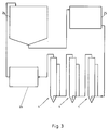
- FIG. 3 shows a schematic representation of a closed water cycle, as it is in fish farms.
- the waste water obtained in a fish silo 24 is first fed to a mechanical cleaning device 25.
- fish-toxic ammonium or ammonia is broken down to nitrite.
- the nitrite is converted into fish-nitrate.
- These first two biological treatment stages use aerobic bacteria. This is followed by the use of anaerobic bacteria and the fact that the oxygen has been completely consumed by the preceding process steps, the conversion of the nitrate into nitrogen.
- This last biological treatment step can also occur in the case of lime addition to the waste water.
- the organically contaminated wastewater is kept for a few minutes in order to enable the most complete possible reaction of the desired type. It is favorable to create particularly advantageous living and metabolic conditions in each biofilm reactor for the bacteria desired there. This can be done by targeted temperature control and / or targeted addition of nutrients or stimulants.
- conditioning 26 is provided for the treated wastewater. Oxygen enrichment, temperature control and pH adjustment of the waste water take place here before it reaches the fish silo 24 again as fresh water. Mechanical filtering of the biomass produced in the biofilm reactors 1 is generally not necessary.
- the water cycle shown in FIG. 3 can be operated almost without the addition of real fresh water ( ⁇ 5% / d) and thus represents a very environmentally friendly possibility for fish production.
Abstract
Description
Die Erfindung bezieht sich auf ein Verfahren zur biologischen Behandlung von organisch belastetem Abwasser. Gleichzeitig befaßt sie sich mit Biofilmreaktoren zur Durchführung des Verfahrens.The invention relates to a method for the biological treatment of organically contaminated wastewater. At the same time, she is concerned with biofilm reactors to carry out the process.
Organisch belastetes Abwasser ist nach gründlicher mechanischer Reinigung zwar klar, es weist jedoch unter anderem noch hohe Ammonium- bzw. Ammoniakkonzentrationen auf. Diese müssen unbedingt beseitigt werden, wenn das Abwasser beispielsweise aus einer Fischproduktionsanlage entstammt und in dieser wieder Verwendung finden soll. Durch aerobe Bakterien läßt sich Ammonium bzw. Ammoniak zu Nitrit und dann zu Nitrat umsetzen. Während Ammonium bzw. Ammoniak eine für Fische giftige Substanz darstellt, ist Nitrat in der Regel als ungiftig anzusehen. Mit Hilfe anaerober Bakterien ist ergänzend die Umwandlung von Nitrat in molekularen Stickstoff möglich. Diese Umwandlung ist ihrerseits wiederum ein wesentlicher Schritt der Trinkwasseraufbereitung. Alle drei hier genannten Umwandlungsschritte vom Ammonium bzw. Ammoniak zum Nitrit, vom Nitrit zum Nitrat und vom Nitrat zum Stickstoff lassen sich durch vergleichbare Maßnahmen initiieren bzw. fördern. Für die jeweils notwendigen Bakterien sind Anlagerungsmöglichkeiten vorzusehen, an denen das organisch belastete Abwasser vorbeigeführt wird. Die ersten beiden Umwandlungen lassen sich zudem durch Sauerstoffzugabe fördern, während für die Letzte Sauerstofffreiheit notwendig ist, die nur (unter Sauerstoffabschluß) nach vorherigem Sauerstoffverbrauch zu erzielen ist.Organically contaminated wastewater is clear after thorough mechanical cleaning, but it still has high ammonium or ammonia concentrations. These must be removed if the wastewater comes from a fish production plant and is to be used again in it. Aerobic bacteria can convert ammonium or ammonia to nitrite and then to nitrate. While ammonium or ammonia is a substance that is toxic to fish, nitrate is generally considered to be non-toxic. With the help of anaerobic bacteria, the conversion of nitrate into molecular nitrogen is also possible. This conversion is in turn an essential step in the treatment of drinking water. All three conversion steps from ammonium or ammonia to nitrite, from nitrite to nitrate and from nitrate to nitrogen can be initiated or promoted by comparable measures. Storage facilities must be provided for the bacteria required in each case, along which the organically contaminated wastewater is led. The first two conversions can also be promoted by adding oxygen, while the last one requires freedom from oxygen, which can only be achieved (with exclusion of oxygen) after previous oxygen consumption.
Aus der DD-A-268 232 ist ein gestreckt ausgebildeter und vertikal angeordneter Reaktionsbehälter bekannt, durch den das organisch belastete Abwasser nach Durchlaufen einer ersten biologischen Behandlungsstufe von unten hindurchgeführt wird. In dem Reaktionsbehälter sind zwei verschiedene Typen von Biofilm-Träger-Teilchen vorgesehen. Der erste Typ weist eine Dichte größer als 1 kg/dm³, vorzugsweise 1,1 bis 1,3 kg/dm³, auf, während der zweite durch eine Dichte kleiner als 1 kg/dm³, vorzugsweise kleiner 0,3 kg/dm³, gekennzeichnet ist. Der erste Typ von Biofilm-Träger-Teilchen bildet im unteren Bereich des Reaktionsbehälters eine Schwebeschicht aus. Der zweite Typ von Biofilter-Träger-Teilchen schwimmt auf dem Abwasser in Reaktionsbehälter aus und bildet so ein schwimmendes Festbett aus. Für die Reinigung des zweiten Typs von Biofilm-Träger-Teilchen im Festbett ist ein Strahlapparat vorgesehen. Dieser saugt von den Biofilm-Träger-Teilchen aufgewachsene Biomasse ab. Für eventuell mitgerissene Biofilm-Träger-Teilchen ist eine Waschvorrichtung im Anschluß an den Strahlapparat vorgesehen, von der aus die gereinigten Biofilm-Träger-Teilchen in das schwimmende Festbett zurückgeführt werden. Der Bodenbereich des Reaktionsbehälters ist zur Verstärkung der Strömung nach unten spitz zulaufend ausgebildet, wobei ein Zuführrohr für das Abwasser mit einer Öffnung gegen den Bodenbereich gerichtet ist. Mit diesem bekannten Biofilmreaktor lassen sich zwei Behandlungsschritte auf einmal durchführen. An den beiden Typen von Biofilm-Träger-Teilchen lagern sich jeweils unterschiedliche Bakterien an. Vorteilhaft ist auch, daß durch die kontinuierliche Reinigung des zweiten Typs von Biofilm-Träger-Teilchen im schwimmenden Festbett gleichbleibende Bedingungen vorliegen. Als nachteilig stellt sich jedoch heraus, daß innerhalb der von dem ersten Typ von Biofilm-Träger-Teilchen gebildeten Schwebschicht mit dem Aufwachsen von Biomasse veränderliche Behandlungsbedingungen für das Abwasser vorliegen. Der Wirkungsgrad des Biofilmreaktors ist demgemäß über der Zeit nicht konstant. Auch die Integration der vorgeschalteten biologischen Behandlungsstufe in den Reaktionsbehälter ergibt eine insgesamt recht aufwendige Vorrichtung, bei der zwar alle drei möglichen Behandlungsschritte gleichzeitig ablaufen, sich jedoch kein konstanter Wirkungsgrad einstellt oder einstellen läßt.From DD-A-268 232 a stretched and vertically arranged reaction container is known, through which the organically contaminated waste water after passing through one first biological treatment stage is passed from below. Two different types of biofilm carrier particles are provided in the reaction vessel. The first type has a density greater than 1 kg / dm³, preferably 1.1 to 1.3 kg / dm³, while the second type is characterized by a density less than 1 kg / dm³, preferably less than 0.3 kg / dm³ is. The first type of biofilm carrier particles forms a floating layer in the lower region of the reaction container. The second type of biofilter carrier particles floats on the wastewater in the reaction vessel and thus forms a floating fixed bed. A blasting apparatus is provided for cleaning the second type of biofilm carrier particles in the fixed bed. This sucks off biomass grown up from the biofilm carrier particles. For any entrained biofilm carrier particles, a washing device is provided in connection to the jet apparatus, from which the cleaned biofilm carrier particles are returned to the floating fixed bed. The bottom region of the reaction vessel is designed to taper to a point to increase the flow, a feed pipe for the waste water having an opening being directed toward the bottom region. With this known biofilm reactor, two treatment steps can be carried out at once. Different bacteria accumulate on the two types of biofilm carrier particles. It is also advantageous that the continuous cleaning of the second type of biofilm carrier particles in the floating fixed bed means that the conditions are constant. However, it turns out to be disadvantageous that within the floating layer formed by the first type of biofilm carrier particles, there are changing treatment conditions for the waste water with the growth of biomass. The efficiency of the biofilm reactor is therefore not constant over time. The integration of the upstream biological treatment stage into the reaction container also results in an overall quite complex device, in which all three possible treatment steps run simultaneously, but no constant efficiency can be set or set.
Aus der DD-A-238 373 ist ein Verfahren zur biologischen Denitrifikation und ein Biofilmreaktor zu dessen Durchführung bekannt. Der Biofilmreaktor weist hier ebenfalls einen gestreckt ausgebildeten und vertikal ausgerichteten Reaktionsbehälter auf, durch den das organisch belastete Abwasser von unten hindurchgeführt wird. Innerhalb des Reaktionsbehälters sind als Biofilm-Träger-Teilchen Abfallprodukte der Braunkohlenschwelkoksvergasung, sogenannte Winkler-Generatorenaschen oder Winkler-Generatorstäube, vorgesehen. Diese bilden eine Schwebschicht, wobei eine bestimmte Steiggeschwindigkeit bzw. damit auch Steighöhe einer bestimmten Schichtdicke der auf den Biofilm-Träger-Teilchen aufgewachsenen Biomasse entspricht. Dies beruht darauf, daß durch die aufgewachsene Biomasse sowohl die mittlere spezifische Masse der Biofilm-Träger-Teilchen absinkt, als auch ihr Strömungswiderstand in dem Abwasser relativ anwächst. Bei diesem bekannten Biofilmreaktor zweigt seitlich von dem Reaktionsbehälter eine Ableitung für aufgestiegene Biofilm-Träger-Teilchen ab. Sobald die Biofilm-Träger-Teilchen innerhalb des Reaktionsbehälters bis auf Höhe der Ableitung angestiegen sind, werden sie durch die Ableitung aus dem Reaktionsbehälter ausgesondert und einer Endlagerung zugeführt. Auf diese Weise werden Biofilm-Träger-Teilchen, die durch aufgewachsene Biomasse weitgehend inaktiviert sind, aus dem Reaktionsbehälter entfernt. Hierdurch wird jedoch der Wirkungsgrad des Biofilmreaktors nicht stabilisiert, da die Anzahl der Biofilm-Träger-Teilchen innerhalb des Reaktionsbehälters ständig abnimmt. Außerdem sind die ausgesonderten Biofilm-Träger-Teilchen von Zeit zu Zeit durch neue zu ersetzen, so daß kein kontinuierlicher Betrieb des Biofilmreaktors möglich ist. Letztlich ist zu beachten, daß eine Endlagerungsmöglichkeit für die ausgesonderten Biofilm-Träger-Teilchen vorzusehen ist.DD-A-238 373 discloses a method for biological denitrification and a biofilm reactor for carrying it out. The biofilm reactor here also has a stretched and vertically oriented reaction vessel through which the organically contaminated wastewater is passed from below. Waste products from the lignite lignite gasification, so-called Winkler generator ash or Winkler generator dust, are provided as biofilm carrier particles within the reaction vessel. These form a floating layer, with a certain rate of climb or therefore also the height of climb corresponding to a certain layer thickness of the biomass grown on the biofilm carrier particles. This is due to the fact that the average specific mass of the biofilm carrier particles decreases as a result of the grown biomass, and their flow resistance in the waste water increases relatively. In this known biofilm reactor, a derivation for ascending biofilm carrier particles branches off from the side of the reaction container. As soon as the biofilm carrier particles within the reaction container have risen to the level of the discharge line, they are separated out of the reaction container by the discharge line and sent to final storage. In this way, biofilm carrier particles which are largely inactivated by grown biomass are removed from the reaction container. However, this does not stabilize the efficiency of the biofilm reactor, since the number of biofilm carrier particles within the reaction container is constantly decreasing. In addition, the separated biofilm carrier particles must be replaced from time to time with new ones, so that continuous operation of the biofilm reactor is not possible. Ultimately is too note that a disposal option for the separated biofilm carrier particles must be provided.
Der Erfindung liegt die Aufgabe zugrunde ein Verfahren zur biologischen Behandlung von organisch belastetem Abwasser aufzuzeigen, daß einen konstanten Wirkungsgrad aufweist und dessen Durchführung kontinuierlich möglich ist. Weiterhin sollen die bekannten Biofilmreaktoren zur Durchführung des neuen Verfahrens weiterentwickelt werden.The invention has for its object to show a method for the biological treatment of organically contaminated wastewater that has a constant efficiency and its implementation is continuously possible. Furthermore, the known biofilm reactors for the implementation of the new process are to be further developed.
Die Aufgabe wird durch ein Verfahren zur biologischen Behandlung von organisch belastetem Abwasser, bei dem das Abwasser von unten durch einen gestreckt ausgebildeten und vertikal ausgerichteten Reaktionsbehälter mit einer derartigen Geschwindigkeit hindurchgeführt wird, daß sich aus Biofilm-Träger-Teilchen, deren spezifische Masse zwischen 1,1 und 1,6 kg/dm³ beträgt, eine Schwebschicht bildet, und bei dem solche Biofilm-Träger-Teilchen, die in dem Reaktionsbehälter eine vorgegebene Steighöhe erreicht haben, von aufgewachsener Biomasse gereinigt werden, gelöst. Auf diese Weise wird ein kontinuierlicher Kreislauf für die Biofilm-Träger-Teilchen geschaffen. Nach der Anlagerung der für den jeweiligen Umwandlungsschritt notwendigen Bakterien, welche bei günstigen Randbedingungen von allein erfolgt, wächst langsam Biomasse auf den Biofilm-Träger-Teilchen auf, wobei sie in dem Reaktionsbehälter kontinuierlich aufsteigen. Beim Erreichen der vorgegebenen Steighöhe, daß heißt auch, einer entsprechenden Biomassendicke werden die Biofilm-Träger-Teilchen von der aufgewachsenen Biomasse gereinigt. Hierdurch gelangen sie wieder in den Anfangszustand vor dem Aufwachsen der Biomasse, der einer geringen Steighöhe entspricht. Nach einer relativ kurzen Anlaufphase stellt sich bei dem neuen Verfahren ein konstanter Wirkungsgrad ein. Der damit erreichte Endzustand ist durch eine weitgehend gleichbleibende Biomassenverteilung auf den Biofilm-Träger-Teilchen gekennzeichnet. Jedes einzelne Biofilm-Träger-Teilchen steigt mit der Zeit innerhalb des Reaktionsbehälters auf und startet nach der Reinigung erneut von unten. Die spezifische Masse der Biofilm-Träger-Teilchen von 1,1 bis 1,6 kg/dm³ erlaubt die Führung des Abwassers durch den bzw. mehrere Reaktionsbehälter mittels einer Pumpe mit einem nur geringen bis mäßigen Leistungserfordernis. In Abhängigkeit von der spezifischen Masse der Biofilm-Träger-Teilchen ist die Geschwindigkeit des Abwassers in dem Reaktionsbehälter zu wählen. Hierbei ist gleichzeitig auch eine Mindestaufenthaltszeit des Abwassers in dem Reaktionsbehälter, die für den Ablauf der gewünschten biologischen Reaktionen notwendig ist, zu berücksichtigen. Bei Anwendung des neuen Verfahrens für die Salzwasserfischzucht ist die spezifische Masse der Biofilm-Träger-Teilchen an die erhöhte Dichte des Salzwassers anzupassen.The object is achieved by a process for the biological treatment of organically contaminated wastewater, in which the wastewater is passed from below through a stretched and vertically oriented reaction vessel at such a speed that biofilm carrier particles whose specific mass is between 1, 1 and 1.6 kg / dm³, forms a floating layer, and in which such biofilm carrier particles which have reached a predetermined height in the reaction vessel are cleaned of grown biomass, dissolved. This creates a continuous cycle for the biofilm carrier particles. After the accumulation of the bacteria necessary for the respective conversion step, which takes place on its own under favorable boundary conditions, biomass slowly grows on the biofilm carrier particles, whereby they rise continuously in the reaction container. When the predetermined height of rise is reached, that is to say also a corresponding biomass thickness, the biofilm carrier particles are cleaned of the grown biomass. As a result, they return to the initial state before the biomass grew up, which corresponds to a low rise. After a relatively short start-up phase, the new process achieves constant efficiency. The final state thus achieved is characterized by a largely constant distribution of biomass on the biofilm carrier particles. Every single biofilm carrier particle increases with time within the reaction container and starts again from the bottom after cleaning. The specific mass of the biofilm carrier particles of 1.1 to 1.6 kg / dm³ allows the wastewater to be led through the reaction tank or tanks by means of a pump with only a low to moderate performance requirement. Depending on the specific mass of the biofilm carrier particles, the speed of the waste water in the reaction vessel must be selected. At the same time, a minimum residence time of the wastewater in the reaction vessel, which is necessary for the desired biological reactions to take place, must also be taken into account. When using the new process for saltwater fish farming, the specific mass of the biofilm carrier particles has to be adapted to the increased density of the salt water.
Die Biofilm-Träger-Teilchen, die die vorgegene Steighöhe erreicht haben, können mit Abstreifbürsten mechanisch gereinigt werden. Es stellt sich als realativ einfach heraus, die Biofilm-Träger-Teilchen konventionell mit Hilfe von Abstreifbürsten mechanisch zu reinigen. Zu diesem Zweck können beispielsweise kontinuierlich umlaufende Abstreifbürsten im oberen Bereich des Reaktionsbehälters vorgesehen sein. Die von den Biofilm-Träger-Teilchen entfernte Biomasse verläßt gemeinsam mit dem behandelten Abwasser den Reaktionsbehälter. Die Biomasse läßt sich, sofern dies notwendig oder gewünscht ist, durch eine nachgeschaltete Reinigung, beispielsweise in einem Absetzbecken problemlos entfernen. Die Biofilm-Träger-Teilchen sinken nach der Reinigung in dem Reaktionsbehälter abwärts, bis sie nach dem erneuten Aufwachsen von Biomasse wieder aufsteigen.The biofilm carrier particles that have reached the opposite height can be mechanically cleaned with wiping brushes. It turns out to be realistically simple to mechanically clean the biofilm carrier particles conventionally with the aid of scraper brushes. For this purpose, continuously rotating wiping brushes can be provided in the upper area of the reaction container, for example. The biomass removed from the biofilm carrier particles leaves the reaction tank together with the treated waste water. The biomass can, if necessary or desired, be easily removed by subsequent cleaning, for example in a sedimentation tank. After cleaning, the biofilm carrier particles sink downward in the reaction vessel until they rise again after biomass has grown again.
Die Biofilm-Träger-Teilchen, die die vorgegebene Steighöhe erreicht haben, können vor oder nach ihrer Reinigung aus dem Reaktionsbehälter ausgesondert und gereinigt dem organisch belasteten Abwasser wieder zugesetzt werden. Wenn die Biofilm-Träger-Teilchen im oberen Bereich des Reaktionsbehälters gereinigt werden und anschließend absinken, führen sie hierbei eine Bewegung aus, die den mit wachsender Biomassendicke aufsteigenden Biofilm-Träger-Teilchen entgegenläuft. Dies ist unter anderem mit einer nicht mehr direkt möglichen Zuordnung von aktueller Steighöhe und aufgewachsener Biomasse bei den Biofilm-Träger-Teilchen verbunden. Günstigere Verhältnisse ergeben sich, wenn die Biofilm-Träger-Teilchen, die die vorgegebene Steighöhe erreicht haben, entweder vor oder erst nach ihrer Reinigung aus dem Reaktionsbehälter ausgesondert werden und in jedem Fall dem organisch belasteten Abwasser in gereinigtem Zustand wieder zugesetzt werden. Dies kann direkt im unteren Bereich des Reaktionsbehälters oder auch schon vor diesem erfolgen. Hierdurch entsteht ein echter, auch räumlich vorhandener Kreislauf für die Biofilm-Träger-Teilchen, der die besten Voraussetzungen für einen stabilen und konstanten Wirkungsgrad des Verfahrens bietet.The biofilm carrier particles that have reached the specified rise height can be removed from the before or after their cleaning The reaction vessels are sorted out and cleaned and added to the organically contaminated wastewater. If the biofilm carrier particles in the upper region of the reaction container are cleaned and then sink, they perform a movement which runs counter to the biofilm carrier particles which increase with increasing biomass thickness. This is associated, among other things, with an assignment of the current height of rise and biomass grown up in the biofilm carrier particles which is no longer directly possible. More favorable conditions result if the biofilm carrier particles which have reached the specified rise height are separated from the reaction vessel either before or only after they have been cleaned and in any case are added to the organically contaminated wastewater in a purified state. This can be done directly in the lower area of the reaction container or even before it. This creates a real, spatially available cycle for the biofilm carrier particles, which offers the best conditions for a stable and constant efficiency of the process.
Die Biofilm-Träger-Teilchen, die die vorgegebene Steighöhe erreicht haben, können aus dem Reaktionsbehälter ausgesondert und dem organisch belasteten Abwasser vor dem Reaktionsbehälter wieder zugesetzt werden, wobei das organisch belastete Abwasser mit den zugesetzten Biofilm-Träger-Teilchen unter Ausbildung einer turbulenten Strömung in den Reaktionsbehälter eingebracht wird, wodurch die zugesetzten Biofilm-Träger-Teilchen gereinigt werden. Die Reinigung der Biofilm-Träger-Teilchen durch eine turbulente Strömung erfordert keinerlei mechanische Vorrichtung und ist aus diesem Grund bei der kontinuierlichen Verfahrensführung bezüglich der Störanfälligkeit besonders vorteilhaft. Hierbei stellt es keinen Nachteil dar, daß die ausgewachsene Biomasse im unteren Bereich des Reaktionsbehälters von den Biofilm-Träger-Teilchen getrennt wird. Die abgelöste Biomasse wird von dem Abwasser mitgeführt und lagert sich nicht erneut an einem Biofilm-Träger-Teilchen an. In diesem Zusammenhang ist auch zu berücksichtigen, daß die anfallende Biomasse nur einen geringen Umfang aufweist. Beim Behandeln von Abwässern innerhalb einer geschlossenen Fischzuchtanlage fallen beispielsweise etwa 0,5 l Schlamm pro m³ Reaktionsbehältervolumen und Tag an.The biofilm carrier particles, which have reached the specified height of rise, can be separated out from the reaction vessel and added to the organically contaminated wastewater upstream of the reaction vessel, the organically contaminated wastewater with the added biofilm carrier particles forming a turbulent flow in the reaction vessel is introduced, whereby the added biofilm carrier particles are cleaned. The cleaning of the biofilm carrier particles by means of a turbulent flow does not require any mechanical device and is therefore particularly advantageous in terms of the susceptibility to faults in the continuous process. It is not a disadvantage here that the fully grown biomass is separated from the biofilm carrier particles in the lower region of the reaction container. The detached biomass will carried by the wastewater and does not attach again to a biofilm carrier particle. In this context, it should also be borne in mind that the biomass produced is of only a small extent. When treating wastewater within a closed fish farm, for example, about 0.5 l of sludge per m³ of reaction container volume and day are generated.
Biofilm-Träger-Teilchen mit einem Durchmesser von etwa 2 - 3 mm und einer spezifischen Masse von ca. 1,15 kg/dm³, die mechanisch beanspruchbar sowie physiologisch unbedenklich sind und eine vorzugsweise rauhe Oberfläche aufweisen, können verwendet werden. Diese Spezifikationen der Biofilm-Träger-Teilchen beinhalten eine weitgehende Optimierung des neuen Verfahrens. Bei einem Durchmesser von ca. 2,5 mm ist die biologisch reaktive Oberfläche der Biofilm-Träger-Teilchen im Vergleich zu dem von ihnen eingenommenen Volumen hinreichend groß. Andererseits erfolgt aber auch zuverlässig ihr Aufsteigen innerhalb des Reaktionsbehälters mit dem Aufwachsen von Biomasse. Hierzu trägt auch die spezifische Masse von ca. 1,15 kg/dm³ bei. Für die Durchführung des neuen Verfahrens im Rahmen einer Salzwasserfischzuchtanlage wäre dieser Wert der höheren Dichte des Salzwassers entsprechend anzupassen. Um eine Beschädigung der Biofilm-Träger-Teilchen bei der Reinigung möglichst weitgehend zu vermeiden, ist es angebracht, diese mechanisch beanspruchbar auszuführen. Da ein gewisser Abrieb in keinem Fall zu vermeiden sein dürfte, sollte das Material der Biofilm-Träger-Teilchen in jedem Fall physiologisch unbedenklich sein. Eine rauhe Oberfläche der Biofilm-Träger-Teilchen erleichtert die Anlage der gewünschten Bakterien sowie der von diesen gebildeten Biomasse. Eine rauhe Oberfläche ist jedoch für die erfolgreiche Durchführung des neuen Verfahrens nicht zwingend erforderlich. Beispielsweise lassen sich auch Biofilm-Träger-Teilchen aus PVC erfolgreich verwenden, die durch eine weitgehend glatte Oberfläche ausgezeichnet sind. Die Form der Biofilm-Träger-Teilchen spielt für die erfolgreiche Durchführung des Verfahrens nur eine sehr untergeordnete Rolle. Beispielsweise sind kugel-, zylinder- und linsenförmige Biofilm-Träger-Teilchen gut geeignet.Biofilm carrier particles with a diameter of about 2-3 mm and a specific mass of about 1.15 kg / dm³, which are mechanically stressable and physiologically harmless and which have a preferably rough surface, can be used. These specifications for the biofilm carrier particles include extensive optimization of the new process. With a diameter of approx. 2.5 mm, the biologically reactive surface of the biofilm carrier particles is sufficiently large compared to the volume they occupy. On the other hand, they rise reliably within the reaction vessel as biomass grows. The specific mass of approx. 1.15 kg / dm³ also contributes to this. For the implementation of the new method in the context of a salt water fish breeding plant, this value would have to be adjusted accordingly to the higher density of the salt water. In order to avoid damage to the biofilm carrier particles as much as possible during cleaning, it is appropriate to make them mechanically stressable. Since a certain abrasion should not be avoided under any circumstances, the material of the biofilm carrier particles should in any case be physiologically harmless. A rough surface of the biofilm carrier particles facilitates the installation of the desired bacteria and the biomass formed by them. However, a rough surface is not absolutely necessary for the successful implementation of the new process. For example, biofilm carrier particles made of PVC can be successfully used, which are characterized by a largely smooth surface. The shape of the Biofilm carrier particles play only a very minor role in the successful implementation of the process. For example, spherical, cylindrical and lenticular biofilm carrier particles are well suited.
Biofilm-Träger-Teilchen aus mit Kreide versetztem Polystyrol können verwendet werden. Dieses Material erfüllt in einfacher Weise die oben aufgelisteten Anforderungen. Über den Kreideanteil läßt sich die spezifische Masse des Polystyrols in vorteilhafter Weise einstellen. Gleichzeitig ist die Kreide für eine angerauhte Oberfläche des Polystyrols ursächlich.Biofilm carrier particles of chalked polystyrene can be used. This material easily meets the requirements listed above. The specific mass of the polystyrene can advantageously be set via the chalk portion. At the same time, the chalk is responsible for a roughened surface of the polystyrene.
Bei einem Biofilmreaktor zur Durchführung des neuen Verfahrens mit einem gestreckt ausgebildeten, vertikal ausgerichteten Reaktionsbehälter, der einen unteren Einlaß für das organisch belastete sowie einen oberen Auslaß für das behandelte Wasser aufweist und zur Aufnahme von Biofilm-Träger-Teilchen bestimmt ist, und einer Reinigungsvorrichtung im oberen Bereich des Reaktionsbehälters besteht die erfinderische Lösung darin, daß als Reinigungsvorrichtung ein drehbares, Abstreifbürsten tragendes Flügelrad vorgesehen ist, dem als Antrieb mindestens eine Wasserstrahldüse zugeordnet ist. Das Abstreifbürsten tragende Flügelrad entfernt die Biomasse von den Biofilm-Träger-Teilchen, die bis in seine Reichweite aufgestiegen sind. Die dem Flügelrad als Antrieb zugeordnete Wasserstrahldüse dient gleichzeitig ebenfalls als Reinigung für die Biofilm-Träger-Teilchen und spült zumindest die abgelöste Biomasse weg. Der Einsatz des Abstreifbürsten tragenden Flügelrads ist unkompliziert, ebenso sein Antrieb über die Wasserstrahldüse. Im Stand der Technik war der Einsatz einer derartigen Reinigungsvorrichtung weder vorgesehen noch möglich, da dort die Reinigungsvorrichtungen ausschließlich für ein aufschwimmendes Festbett vorgesehen waren.In a biofilm reactor for carrying out the new process with a stretched, vertically oriented reaction vessel which has a lower inlet for the organically loaded and an upper outlet for the treated water and is intended for receiving biofilm carrier particles, and a cleaning device in In the upper area of the reaction container, the inventive solution consists in that a rotatable impeller wheel carrying scraper brushes is provided as the cleaning device, to which at least one water jet nozzle is assigned as the drive. The impeller carrying scraper brushes removes the biomass from the biofilm carrier particles, which have risen to its range. The water jet nozzle assigned to the impeller as the drive also serves at the same time as cleaning for the biofilm carrier particles and at least rinses away the detached biomass. The use of the impeller carrying scraper brushes is straightforward, as is its drive via the water jet nozzle. In the prior art, the use of such a cleaning device was neither intended nor possible, since the cleaning devices were only intended for a floating fixed bed.
Bei einem weiteren Biofilmreaktor zur Durchführung des neuen Verfahrens mit einem gestreckt ausgebildeten, vertikal ausgerichteten Reaktionsbehälter, der einen unteren Einlaß für das organisch belastete sowie einen oberen Auslaß für das behandelte Abwasser aufweist und zur Aufnahme von Biofilm-Träger-Teilchen bestimmt ist, und einer seitlich von dem Reaktionsbehälter abzweigenden Ableitung für aufgestiegene Biofilm-Träger-Teilchen besteht die erfinderische Lösung darin, daß der Reaktionsbehälter einen spitz zulaufenden Bodenbereich aufweist, daß ein bis in den Reaktionsbehälter hinreinragendes Zuführrohr für das organisch belastete Abwasser mit einer gegen den Bodenbereich gerichteten Öffnung des unteren Einlaß bildet, und daß die Ableitung in Form eines Injektors in das Zuführrohr mündet. Bei diesem Biofilmreaktor kann ganz auf mechanisch bewegte Teile verzichtet werden. Dadurch wird ein hoher Grad an Zuverlässigkeit erreicht. Dennoch erfolgt die Reinigung der Biofilm-Träger-Teilchen, die eine vorgegebene Steighöhe innerhalb des Reaktionsbehälters erreicht haben, in dem notwendigen Umfang. Die hierzu verwandte turbulente Strömung wird durch die Anordnung des Zuführrohrs für das organisch belastete Abwasser gegenüber dem spitz zulaufenden Bodenbereich des Reaktionsbehälters erreicht. Die mit dieser Ausformung des Bodenbereichs einhergehende Querschnittsverringerung führt zu einer dort ausgeprägt hohen Strömungsgeschwindigkeit, die ursächlich für den Reinigungseffekt der dem Abwasser zugesetzten Biofilm-Träger-Teilchen ist. Das Zusetzen der aus dem Reaktionsbehälter ausgesonderten Biofilm-Träger-Teilchen erfolgt mit Hilfe eines Injektors. Dieser wird von dem Zuführrohr für das Abwasser und der in dieses hineinmündenden Ableitung für die Biofilm-Träger-Teilchen gebildet. Die Saugwirkung des Injektors wird auch zur Aussonderung der Biofilm-Träger-Teilchen genutzt, die die vorgegebene Steighöhe innerhalb des Reaktionsbehälters erreicht haben. Diese Steighöhe entspricht der Stelle, an der die Ableitung von dem Reaktionsbehälter abzweigt.In a further biofilm reactor for carrying out the new process with a stretched, vertically oriented reaction vessel which has a lower inlet for the organically contaminated and an upper outlet for the treated waste water and is intended for receiving biofilm carrier particles, and one laterally The inventive solution consists of the discharge line for ascending biofilm carrier particles branching off from the reaction vessel in that the reaction vessel has a tapering bottom region, that a feed pipe for the organically contaminated waste water protruding into the reaction vessel with an opening of the lower inlet directed towards the bottom region forms, and that the discharge in the form of an injector opens into the feed pipe. With this biofilm reactor, mechanically moving parts can be dispensed with entirely. This ensures a high degree of reliability. Nevertheless, the cleaning of the biofilm carrier particles, which have reached a predetermined height of rise within the reaction vessel, takes place to the necessary extent. The turbulent flow used for this is achieved by arranging the feed pipe for the organically contaminated wastewater in relation to the tapering bottom region of the reaction vessel. The reduction in cross-section associated with this shape of the bottom area leads to a markedly high flow rate there, which is the cause of the cleaning effect of the biofilm carrier particles added to the waste water. The biofilm carrier particles separated from the reaction container are added with the aid of an injector. This is formed by the feed pipe for the wastewater and the discharge for the biofilm carrier particles opening into it. The suction effect of the injector is also used to separate out the biofilm carrier particles that have reached the specified height of rise within the reaction container. This climbing height corresponds the place where the discharge branches off from the reaction vessel.
Ein oberer Abschnitt des Reaktionsbehälters kann durchsichtig ausgebildet sein. Zur Einstellung des neuen Biofilmreaktors wird sinnvollerweise beobachtet, ob nach einer Betriebszeit, die üblicherweise zum Aufwachsen der maximal gewünschten Biomassendicke auf die Biofilm-Träger-Teilchen ausreicht, die ersten Biofilm-Träger-Teilchen die vorgegebene Steighöhe erreicht haben. Ist dies nicht der Fall, muß die Strömungsgeschwindigkeit des Abwassers durch den Reaktionsbehälter entsprechend erhöht werden. Erfolgt das Erreichen der vorgegebenen Steighöhe hingegen zu früh, so ist die Geschwindigkeit des Abwassers entsprechend zu reduzieren. Hieraus ergibt sich zwangsläufig, daß die neuen Biofilmreaktoren für schwankende Durchsatzmengen an Abwasser weniger geeignet sind. Idealerweise werden sie für einen vorgegebenen Abwasserdurchsatz dimensioniert und führen bei diesem zu einem exzellenten Wirkungsgrad bei einem geringen Raumbedarf und niedrigen Unterhaltungskosten. Eine Reihen- oder Parallelschaltung mehrerer Reaktoren ist ohne zusätzliche Pumpen problemlos möglich.An upper section of the reaction container can be made transparent. To adjust the new biofilm reactor, it is sensibly observed whether after an operating time which is usually sufficient to grow the maximum desired biomass thickness onto the biofilm carrier particles, the first biofilm carrier particles have reached the predetermined height of rise. If this is not the case, the flow rate of the waste water through the reaction vessel must be increased accordingly. If, on the other hand, the specified climbing height is reached too early, the speed of the wastewater must be reduced accordingly. This inevitably means that the new biofilm reactors are less suitable for fluctuating throughputs of wastewater. Ideally, they are dimensioned for a given wastewater throughput and lead to an excellent efficiency with a small space requirement and low maintenance costs. A series or parallel connection of several reactors is possible without additional pumps.
Das Zuführrohr kann einen Druckluftanschluß aufweisen. Für sicherlich selten notwendige, aber vielleicht von Zeit zu Zeit doch durchzuführende Reinigungen des gesamten Biofilmreaktors ist es sinnvoll, dem Zuführrohr einen Druckluftanschluß aufzuweisen. Druckluft ist als Reinigungsmedium für Biofilmreaktoren und gleichartige Vorrichtungen aus dem Stand der Technik bekannt.The feed pipe can have a compressed air connection. For cleaning of the entire biofilm reactor which is certainly rarely necessary, but which may need to be carried out from time to time, it makes sense to have a compressed air connection to the feed pipe. Compressed air is known from the prior art as a cleaning medium for biofilm reactors and similar devices.
Die Erfindung wird im Folgenden anhand von Ausführungsbeispielen näher erläutert und beschrieben. Es zeigt:
Figur 1- eine erste Ausführungsform eines Biofilmreaktors zur Durchführung des Verfahrens zur biologischen Behandlung von organisch belastetem Wasser,
Figur 2- eine Ausführungsform eines zweiten Biofilmreaktor zur Durchführung des Verfahrens zur biologischen Behandlung von organisch belastetem Abwasser,
Figur 3- das Blockschaltbild einer Fischzuchtanlage als Anwendungsbeispiel für das Verfahren zur biologischen Behandlung von organisch belastetem Abwasser.
- Figure 1
- a first embodiment of a biofilm reactor to carry out the method for the biological treatment of organically contaminated water,
- Figure 2
- an embodiment of a second biofilm reactor for carrying out the method for the biological treatment of organically contaminated wastewater,
- Figure 3
- the block diagram of a fish farm as an application example for the method for the biological treatment of organically contaminated wastewater.
Der in Figur 1 dargestellte Biofilmreaktor 1 weist einen gestreckt ausgebildeten, vertikal ausgerichteten Reaktionsbehälter 2 auf. Der Reaktionsbehälter 2 ist zur Aufnahme von Biofilm-Träger-Teilchen 3 bestimmt. Die Biofilm-Träger-Teilchen 3 bestehen aus mit Kreide versetztem Polystyrol, dessen spezifische Masse etwa 1,15 kg/dm³ beträgt. Die Oberfläche der Biofilm-Träger-Teilchen ist durch den Kreidezusatz angerauht, so daß sich hier leicht Bakterien anlagern können. Die Form der Biofilm-Träger-Teilchen ist nahezu beliebig, während ihre maximalen Abmessungen etwa 2 bis 3 mm betragen sollten. Hier sind Biofilm-Träger-Teilchen 3 in Kugelform mit einem Durchmesser von 2,5 mm vorgesehen. Die Biofilm-Träger-Teilchen 3 bilden in durch den Reaktionsbehälter 2 geführtem organisch belastetem Abwasser 4 eine Schwebschicht 5. Für die Führung des Abwassers 4 ist eine Pumpe 6 dem Biofilmreaktor 1 vorgeschaltet. Von der Pumpe 6 gelangt das Abwasser 4 durch einen unteren Einlaß 7 mit Rückhaltevorrichtung in den Reaktionsbehälter 2. Nach Kontakt mit den Biofilm-Träger-Teilchen 3 verläßt das Abwasser 4 den Reaktionsbehälter 2 durch einen oberen Auslaß 8 und ein diesem vorgeschaltetes Lamellensieb 9. An den Biofilm-Träger-Teilchen 3 lagern sich zuerst im Abwasser 4 enthaltene Bakterien an. Der Typus der Bakterien, der hierbei vornehmlich auftritt, hängt von dem Zustand des Abwassers 4 ab. Ist das Abwasser 4 mit Ammonium bzw. Ammoniak belastet und hinreichend sauerstoffhaltig, lagern sich an den Biofilm-Träger-Teilchen 3 aerobe Bakterien (Nitrosomonas, Nitrobacter) ab, die Ammonium bzw. Ammoniak zu Nitrit umwandeln. In nitrithaltigem Abwasser 4 wandeln die an den Biofilm-Träger-Teilchen 3 angelagerten Bakterien Nitrit zu Nitrat um. Bei sauerstoffarmem, nitrathaltigem Abwasser 4 ist die Umwandlung des Nitrats durch anaerobe Bakterien zu Stickstoff möglich. In jedem Fall wächst mit der erfolgenden Bioreaktion Biomasse auf den Biofilm-Träger-Teilchen 3 auf. Hierdurch wird die spezifische Masse der Biofilm-Träger-Teilchen 3 und auch ihr relativer strömungswiderstand erhöht. Auf diese Weise bestimmt die auf einem einzelnen Biofilm-Träger-Teilchen aufgewachsene Biomasse die Steiggeschwindigkeit des Biofilm-Träger-Teilchens und damit auch seine relative Steighöhe gegenüber den anderen Biofilm-Träger-Teilchen 3 innerhalb der Schwebschicht 5. Sobald auf den einzelnen Biofilm-Träger-Teilchen 3 eine gewissen Menge Biomasse aufgewachsen ist, steigt es innerhalb des Reaktionsbehälters 2 bis in den Bereich eines Flügelrades 10 auf. Das Flügelrad 10 ist um eine Achse 11 drehbar gelagert und trägt Abstreifbürsten 12. Als Antrieb sind dem Flügelrad 10 Wasserstrahldüsen 13 zugeordnet. Die in den Bereich des Flügelrads 10 aufgestiegenen Biofilm-Träger-Teilchen 3 werden durch die bewegten Abstreifbürsten 12 von aufgewachsener Biomasse gereinigt. Die Wasserstrahldüsen 13 dienen in diesem Zusammenhang nicht nur zum Antrieb des Flügelrads 10 sondern auch als Hilfsmittel bei der Reinigung der Biofilm-Träger-Teilchen, in dem sie die abgelöste Biomasse wegspülen. Die von den Biofilm-Träger-Teilchen 3 entfernte Biomasse verläßt mit dem Abwasser 4 den Reaktionsbehälter 2 durch den Auslaß 8 bzw. das Lamellensieb 9. Die gereinigten Biofilm-Träger-Teilchen 3 sinken, da sie nun wieder eine relativ große spezifische Masse und einen geringen relativen Strömungswiderstand aufweisen, innerhalb des Reaktionsbehälters 2 herab. Beim Betrieb des Biofilmreaktors 1 liegt nach einer gewissen Einlaufphase ein über der Zeit konstanter Wirkungsgrad vor. Die Biofilm-Träger-Teilchen 3 weisen dann eine gleichbleibende mittlere Schichtdicke der aufgewachsenen Biomasse auf. Zu jeder Zeit wird genausoviel Biomasse mit dem Abwasser 4 aus dem Reaktionsbehälter 2 herausgeführt wie in diesem auf den Biofilm-Träger-Teilchen 3 anwächst. Die Mengen der von dem Biofilmreaktor 1 ausgestoßenen Biomasse sind jedoch in der Regel sehr gering, so daß in vielen Fällen auf eine Nachreinigung verzichtet werden kann. Beispielsweise fällt bei dem Betrieb in einem geschlossenen Wasserkreislauf einer Fischzuchtanlage pro m³ Reaktionsbehältervolumen und Tag nur ein halber Liter Schlamm an. Die Einstellung des Biofilmreaktors 1 erfolgt nach der Maßgabe, daß die Förderleistung nach der Pumpe 6 gerade so groß ist, daß die durch aufgewachsene Biomasse inaktiv werdenden Biofilm-Träger-Teilchen 3 in den Bereich des Flügelrads 10 gelangen. Dort werden sie von der Biomasse gereinigt und dadurch reaktiviert. Die Einstellung des Biofilmreaktors 1 wird dadurch erleichtert, daß ein oberer Abschnitt 14 des Reaktionsbehälters 2 aus durchsichtigem Acrylglas gefertigt ist. Ein unterer Abschnitt 15 ist hingegen aus Metall gearbeitet, um den dort auftretenden größeren hydrostatischen Drücken widerstehen zu können. Vorteilhaft bei dem neuen Biofilmreaktor 1 und dem mit ihm durchzuführenden Verfahren ist, daß nach einmaliger Einstellung ein konstanter Wirkungsgrad bei der Behandlung von organisch behandeltem Abwasser vorliegt und dieser über lange Zeit, ohne notwendige äußere Manipulationen erhalten bleibt. Hierfür ist im Vergleich zu anderen Verfahren, die auf Riesel- bzw. Tropfkörpern oder Belebtschlammkulturen aufbauen, nur ein geringer Platzbedarf vorhanden.The
Der in Figur 2 dargestellte Biofilmreaktor 1 unterscheidet sich von dem Biofilmreaktor 1 gemäß Figur 1 im wesentlichen durch die Art der Reinigung, die für die Biofilm-Träger-Teilchen 3 beim Erreichen einer vorgegebenen Steighöhe vorgesehen ist. Von dem Reaktionsbehälter 2 zweigt eine Ableitung 16 ab, mit deren Hilfe alle die Biofilm-Träger-Teilchen 3 aus dem Reaktionsbehälter 2 ausgesondert werden, die bis in die Höhe der Abzweigung aufgestiegen sind. Die Ableitung 16 mündet in ein Zuführrohr 17 für das Abwasser 4 unter Ausbildung eines Injektors 18. Das durch die Pumpe 6 in den Biofilmreaktor 1 geführte Abwasser 4 reißt hierbei den Inhalt der Ableitung 16 samt der Biofilm-Träger-Teilchen 3 mit. Der Bodenbereich 19 des Reaktionsbehälters 2 bzw. dessen unteren Abschnitts 15 ist nach unten spitz zulaufend ausgebildet, wobei das Zuführrohr 17 für das Abwasser 4 bis in den Reaktionsbehälter 2 hineinragt und mit einer gegen den Bodenbereich 19 gerichteten Öffnung 20 den unteren Einlaß 7 bildet. Die Querschnittverengung im Bodenbereich 16 und die Ausrichtung des das Abwasser 4 in den Behälter 2 einführenden Zuführrohrs 17 begünstigen die Ausbildung einer turbulenten Strömung 21 innerhalb des Bodenbereichs 19. Diese turbulente Strömung 21 bewirkt eine Reinigung der vom Abwasser 4 mitgeführten Biofilm-Träger-Teilchen 3. Vorteilhaft sind hierzu keine mechanischen Vorrichtungen notwendig. Sinnvollerweise ist das Material der Biofilm-Träger-Teilchen 3 so auszuwählen, daß diese den Belastungen unter anderem bei Zusammenstößen mit der Wandung des Bodenbereichs 19 widerstehen. Biofilm-Träger-Teilchen 3 aus mit Kreide versetztem Polystyrol werden dieser Anforderung gerecht. Die durch die turbulente Strömung 21 abgelöste Biomasse lagert sich nicht erneut innerhalb des Reaktionsbehälters 2 an Biofilm-Träger-Teilchen 3 ab. Sie verläßt gemeinsam mit dem Abwasser 4 durch das Lamellensieb 9 den Biofilmreaktor 1. Das Lamellensieb 9 dient nur der Aufgabe, "verirrte" Biofilm-Träger-Teilchen 3 in dem Reaktionsbehälter 2 zurückzuhalten. Mit dem Biofilmreaktor 1 gemäß Figur 2 ist der große Vorteil verbunden, daß die Biofilm-Träger-Teilchen 3 in einen echten Kreislauf geführt werden. Sie müssen nicht entgegen ihrer Aufsteigrichtung beim Aufwachsen von Biomasse nach dem Reinigen innerhalb des Reaktionsbehälters 2 absinken. So entspricht die in dem Reaktionsbehälter 2 vorliegende Steighöhenverteilung der Biofilm-Träger-Teilchen 3 in jedem Fall auch der auf ihnen aufgewachsenen Biomasse. Auf diese Weise kann das Prinzip, daß die Biofilm-Träger-Teilchen 3, die die meiste aufgewachsene Biomasse aufweisen, gereinigt und im gereinigten Zustand für erneute biologische Reaktionen zur Verfügung gestellt werden, besonders zuverlässig realisiert werden. Hiermit ist eine exzellente Einhaltung des angestrebten Wirkungsgrades des Biofilmreaktors 1 bei der Behandlung von organisch belastetem Abwasser 4 gewährleistet. An dieser Stelle sei jedoch nochmals darauf verwiesen, daß eine Einstellung des Biofilmreaktors 1 auf stark schwankende Durchsatzmengen von Abwasser 4 nicht vorgesehen ist. Vielmehr sollte das Volumen des Reaktionsbehälters 2 auf die anfallenden Mengen an Abwasser 4 abgestimmt werden. Die Pumpe 6 ist analog zu der Pumpe 6 gemäß Figur 1 so auszuregeln, daß die durch Aufwachsen von Biomasse weitgehend inaktiven Biofilm-Träger-Teilchen 3 innerhalb des Reaktionsbehälters 2 eine solche Steighöhe erreichen, die der abzweigenden Ableitung 16 entspricht. Zwischen der Pumpe 6 und dem Injektor 18 ist gemäß Figur 2 eine Rückschlagklappe 22 und ein Drucklustanschluß 23 vorgesehen, mit deren Hilfe eine gründliche Reinigung des Biofilmreaktors 1 möglich ist. Diese Reinigung wird jedoch nur relativ selten erforderlich sein. Das neue Verfahren läßt sich ohne Unterbrechungen kontinuierlich und langfristig durchführen, da beispielsweise keine verbrauchten Biofilm-Träger-Teilchen 3 zu ersetzen sind.The
Figur 3 gibt in schematischer Darstellung einen geschlossenen Wasserkreislauf wieder, wie er bei Fischzuchtanlagen vorliegt. Das in einem Fischsilo 24 anfallende Abwasser wird zuerst einer mechanischen Reinigung 25 zugeführt. Im Anschluß daran erfolgt die biologische Behandlung des nur noch mit gelösten organischen Stoffen belasteten Abwassers. Hierzu sind in diesem Fall drei Biofilmreaktoren 1 gemäß Figur 2 hintereinander geschaltet vorgesehen. In dem ersten Biofilmreaktor 1 erfolgt der Abbau von fischgiftigem Ammonium bzw. Ammoniak zu Nitrit. Im zweiten Biofilmreaktor 1 wird das Nitrit in fischungiftiges Nitrat umgesetzt. Diese ersten beiden biologischen Behandlungsstufen bedienen sich aerober Bakterien. Im Anschluß erfolgt unter Verwendung anaerober Bakterien und der Nutzung des Umstandes, daß durch die vorangeschalteten Verfahrensstufen der Sauerstoff vollständig verbraucht wurde, die Umwandlung des Nitrats in Stickstoff. Dieser letzte biologische Behandlungsschritt kann bei Kalkzusatz zu dem Abwasser auch in Fortfall kommen. In jedem der Biofilmreaktoren 1 hält sich das organisch belastete Abwasser einige Minuten lang auf, um eine möglichst vollständige Reaktion der gewünschten Art zu ermöglichen. Günstig ist es, in jedem Biofilmreaktor für die dort gewünschten Bakterien besonders vorteilhafte Lebens- und Stoffwechselbedingungen zu schaffen. Dies kann durch eine gezielte Temperierung und/oder gezielte Zugabe von Nährstoffen bzw. Stimulantien erfolgen. Im Anschluß an die Biofilmreaktoren 1 ist ein Konditionierung 26 für das aufbereitete Abwasser vorgesehen. Hier erfolgt eine Sauerstoffanreicherung, Temperierung und pH-Wert- Einstellung des Abwassers, bevor es als Frischwasser erneut in den Fischsilo 24 gelangt. Ein mechanisches Abfiltern der in den Biofilmreaktoren 1 anfallenden Biomasse ist in aller Regel nicht notwendig. Der in Figur 3 dargestellte Wasserkreislauf ist nahezu ohne die Zugabe von echtem Frischwasser (<5 %/d) betreibbar und stellt damit eine sehr umweltfreundliche Möglichkeit für die Fischproduktion dar.Figure 3 shows a schematic representation of a closed water cycle, as it is in fish farms. The waste water obtained in a
Claims (10)
Applications Claiming Priority (2)
| Application Number | Priority Date | Filing Date | Title |
|---|---|---|---|
| DE9016202U | 1990-11-22 | ||
| DE19909016202 DE9016202U1 (en) | 1990-11-22 | 1990-11-22 |
Publications (1)
| Publication Number | Publication Date |
|---|---|
| EP0486748A1 true EP0486748A1 (en) | 1992-05-27 |
Family
ID=6859788
Family Applications (1)
| Application Number | Title | Priority Date | Filing Date |
|---|---|---|---|
| EP19910105364 Withdrawn EP0486748A1 (en) | 1990-11-22 | 1991-04-04 | Process and biofilm reactors for biological treatment of organically polluted waste water |
Country Status (2)
| Country | Link |
|---|---|
| EP (1) | EP0486748A1 (en) |
| DE (1) | DE9016202U1 (en) |
Cited By (5)
| Publication number | Priority date | Publication date | Assignee | Title |
|---|---|---|---|---|
| GB2334029A (en) * | 1998-02-04 | 1999-08-11 | John James Todd | Media for waste water treatment |
| EP1757561A2 (en) * | 2005-08-23 | 2007-02-28 | Hozelock Limited | Pond filters |
| WO2019121285A1 (en) * | 2017-12-22 | 2019-06-27 | Jassen - Kunststoffzentrum Gmbh - Apparatebau, Zuschnitte Und Formung | Bioreactor and use thereof, method for producing an organic nutrient solution, organic nutrient solution, substrate material and use thereof for cultivating plants |
| WO2020254242A1 (en) * | 2019-06-17 | 2020-12-24 | Jassen - Kunststoffzentrum Gmbh - Apparatebau, Zuschnitte Und Formung | Bioreactor and use thereof, method for producing an organic nutrient solution and for carbon dioxide storage |
| US20210162343A1 (en) * | 2019-12-03 | 2021-06-03 | Bonno Koers | Method and device for removing ammonia from exhaust air from a livestock stable |
Families Citing this family (2)
| Publication number | Priority date | Publication date | Assignee | Title |
|---|---|---|---|---|
| DE9016202U1 (en) * | 1990-11-22 | 1991-03-28 | Meylahn, Gerd-Uwe, Dr., O-1501 Gross-Glienicke, De | |
| DE4214004C1 (en) * | 1992-04-29 | 1993-05-19 | Fischtechnik Fredelsloh, Dr. Gerhard Mueller Gmbh, 3413 Moringen, De | Bio-film reactor for biological treatment of waste water - comprising vertical reaction chamber contg. perforated impact wall to separate biomass |
Citations (8)
| Publication number | Priority date | Publication date | Assignee | Title |
|---|---|---|---|---|
| US3779906A (en) * | 1972-08-03 | 1973-12-18 | Biospherics Inc | Plastic moving-surface treatment of sewage |
| US4009099A (en) * | 1974-07-12 | 1977-02-22 | Ecolotrol, Inc. | Apparatus and process for removing ammonia nitrogen from waste water |
| FR2446259A1 (en) * | 1979-01-12 | 1980-08-08 | Degremont | Treating nitrogen polluted water in a bacterial bed - with support material recirculation to remove excess microorganisms |
| EP0124409A1 (en) * | 1983-04-28 | 1984-11-07 | L'air Liquide, Societe Anonyme Pour L'etude Et L'exploitation Des Procedes Georges Claude | Process and apparatus for the regeneration of solid particles covered by a biomass |
| DD238373A1 (en) * | 1985-06-19 | 1986-08-20 | Tech Hochschule C Schorlemmer | PROCESS FOR BIOLOGICAL DENITRIFICATION |
| DE3518490A1 (en) * | 1985-05-23 | 1986-11-27 | WSW Planungsgesellschaft mbH, 4355 Waltrop | Device for biological waste water treatment |
| EP0389958A1 (en) * | 1989-03-25 | 1990-10-03 | Preussag Aktiengesellschaft | Process for biochemical treatment of water |
| DE9016202U1 (en) * | 1990-11-22 | 1991-03-28 | Meylahn, Gerd-Uwe, Dr., O-1501 Gross-Glienicke, De |
-
1990
- 1990-11-22 DE DE19909016202 patent/DE9016202U1/de not_active Expired - Lifetime
-
1991
- 1991-04-04 EP EP19910105364 patent/EP0486748A1/en not_active Withdrawn
Patent Citations (8)
| Publication number | Priority date | Publication date | Assignee | Title |
|---|---|---|---|---|
| US3779906A (en) * | 1972-08-03 | 1973-12-18 | Biospherics Inc | Plastic moving-surface treatment of sewage |
| US4009099A (en) * | 1974-07-12 | 1977-02-22 | Ecolotrol, Inc. | Apparatus and process for removing ammonia nitrogen from waste water |
| FR2446259A1 (en) * | 1979-01-12 | 1980-08-08 | Degremont | Treating nitrogen polluted water in a bacterial bed - with support material recirculation to remove excess microorganisms |
| EP0124409A1 (en) * | 1983-04-28 | 1984-11-07 | L'air Liquide, Societe Anonyme Pour L'etude Et L'exploitation Des Procedes Georges Claude | Process and apparatus for the regeneration of solid particles covered by a biomass |
| DE3518490A1 (en) * | 1985-05-23 | 1986-11-27 | WSW Planungsgesellschaft mbH, 4355 Waltrop | Device for biological waste water treatment |
| DD238373A1 (en) * | 1985-06-19 | 1986-08-20 | Tech Hochschule C Schorlemmer | PROCESS FOR BIOLOGICAL DENITRIFICATION |
| EP0389958A1 (en) * | 1989-03-25 | 1990-10-03 | Preussag Aktiengesellschaft | Process for biochemical treatment of water |
| DE9016202U1 (en) * | 1990-11-22 | 1991-03-28 | Meylahn, Gerd-Uwe, Dr., O-1501 Gross-Glienicke, De |
Cited By (11)
| Publication number | Priority date | Publication date | Assignee | Title |
|---|---|---|---|---|
| GB2334029A (en) * | 1998-02-04 | 1999-08-11 | John James Todd | Media for waste water treatment |
| EP1757561A2 (en) * | 2005-08-23 | 2007-02-28 | Hozelock Limited | Pond filters |
| EP1757561A3 (en) * | 2005-08-23 | 2007-05-02 | Hozelock Limited | Pond filters |
| WO2019121285A1 (en) * | 2017-12-22 | 2019-06-27 | Jassen - Kunststoffzentrum Gmbh - Apparatebau, Zuschnitte Und Formung | Bioreactor and use thereof, method for producing an organic nutrient solution, organic nutrient solution, substrate material and use thereof for cultivating plants |
| CN111492048A (en) * | 2017-12-22 | 2020-08-04 | 扎森器具切割和定型塑胶中心有限公司 | Bioreactor and use thereof, method for producing an organic nutrient solution, matrix material and use thereof for cultivating plants |
| AU2018391487B2 (en) * | 2017-12-22 | 2020-12-10 | Jassen - Kunststoffzentrum Gmbh - Apparatebau, Zuschnitte Und Formung | Bioreactor and use thereof, method for producing an organic nutrient solution, organic nutrient solution, substrate material and use thereof for cultivating plants |
| RU2759844C1 (en) * | 2017-12-22 | 2021-11-18 | Яссен - Кунстштоффцентрум ГмбХ - Аппаратебау, Цушнитте унд Формунг | Bioreactor and application thereof, method for producing organic nutrient solution, organic nutrient solution, substrate material and application thereof for plant cultivation |
| CN111492048B (en) * | 2017-12-22 | 2022-08-19 | 扎森器具切割和定型塑胶中心有限公司 | Method for preparing organic nutrient solution by using bioreactor |
| US11672214B2 (en) | 2017-12-22 | 2023-06-13 | Jassen—Kunststoffzentrum GmbH—Apparatebau, Zuschnitte und Formung | Bioreactor and use thereof, method for producing an organic nutrient solution, organic nutrient solution, substrate material and use thereof for cultivating plants |
| WO2020254242A1 (en) * | 2019-06-17 | 2020-12-24 | Jassen - Kunststoffzentrum Gmbh - Apparatebau, Zuschnitte Und Formung | Bioreactor and use thereof, method for producing an organic nutrient solution and for carbon dioxide storage |
| US20210162343A1 (en) * | 2019-12-03 | 2021-06-03 | Bonno Koers | Method and device for removing ammonia from exhaust air from a livestock stable |
Also Published As
| Publication number | Publication date |
|---|---|
| DE9016202U1 (en) | 1991-03-28 |
Similar Documents
| Publication | Publication Date | Title |
|---|---|---|
| DE2721723A1 (en) | ACTIVATED SLUDGE PROCESS FOR WASTE WATER TREATMENT AND DEVICE FOR CARRYING OUT THE PROCESS | |
| DE19644457A1 (en) | Granular carrier for treating waste water or waste water, process for its production and device for treating dirty water or waste water using the granular carrier | |
| WO1990002100A1 (en) | Process and device for microbiological water treatment | |
| DE3427448A1 (en) | METHOD AND DEVICE FOR BIOLOGICAL WASTE WATER TREATMENT | |
| DE60033990T2 (en) | Process for water treatment using a denitrification conveyor | |
| DE2237929C2 (en) | Method for removing contaminants from an exhaust gas | |
| DE4110026A1 (en) | Biological waste water clarifier with inert gas recirculation - in which gas is circulated through vessel so that oxygen@ content is reduced and water is agitated without introducing oxygen@ | |
| EP0389958B1 (en) | Process for biochemical treatment of water | |
| EP0486748A1 (en) | Process and biofilm reactors for biological treatment of organically polluted waste water | |
| CH616639A5 (en) | Process and apparatus for removing ammonia nitrogen from effluents | |
| AT392460B (en) | METHOD FOR BIOLOGICAL WASTE WATER TREATMENT | |
| DE10043595B4 (en) | water filters | |
| DE2033669A1 (en) | Method and device for Be act of wastewater or the like | |
| DE3508916A1 (en) | Process and installation for purifying waste water | |
| EP1783102B1 (en) | Process for the aerobic microbiologic wastewater treatment | |
| WO2006111235A1 (en) | Method and system for treating and preparing water circulating in aquaculture systems | |
| EP0072837A1 (en) | Method, device and means for purifying waste waters | |
| DE2420744C3 (en) | Device for purifying waste water | |
| EP2100856B1 (en) | Method for microbiological treatment of water | |
| EP0501355B1 (en) | Anaerobic water treatment process, in particular for the microbial elimination of nitrate from drinking water | |
| DE2936826A1 (en) | Biological treatment of waste water - using suspended plastic bodies with microbial growth on their surfaces and air injection | |
| CH667641A5 (en) | METHOD FOR AUTOTROPHIC DENITRIFICATION OF WATER. | |
| EP0503546A1 (en) | Process for biological purification of water | |
| DE10155190A1 (en) | Fish farming water treatment process for fresh- or salt-water has main cascading loop and two sub-loops | |
| DE4312891C1 (en) | Decontaminating aq. sludges by removal of gaseous and liq. harmful substances - by microbiological oxidn. with water-filled porous microorganism carrier body on the surface of the sludge |
Legal Events
| Date | Code | Title | Description |
|---|---|---|---|
| PUAI | Public reference made under article 153(3) epc to a published international application that has entered the european phase |
Free format text: ORIGINAL CODE: 0009012 |
|
| AK | Designated contracting states |
Kind code of ref document: A1 Designated state(s): DE DK ES GB NL SE |
|
| 17P | Request for examination filed |
Effective date: 19920709 |
|
| 17Q | First examination report despatched |
Effective date: 19930303 |
|
| STAA | Information on the status of an ep patent application or granted ep patent |
Free format text: STATUS: THE APPLICATION IS DEEMED TO BE WITHDRAWN |
|
| 18D | Application deemed to be withdrawn |
Effective date: 19930913 |