EP0486726B1 - Liquid ring pump - Google Patents
Liquid ring pump Download PDFInfo
- Publication number
- EP0486726B1 EP0486726B1 EP19900122405 EP90122405A EP0486726B1 EP 0486726 B1 EP0486726 B1 EP 0486726B1 EP 19900122405 EP19900122405 EP 19900122405 EP 90122405 A EP90122405 A EP 90122405A EP 0486726 B1 EP0486726 B1 EP 0486726B1
- Authority
- EP
- European Patent Office
- Prior art keywords
- separator
- ring pump
- liquid ring
- condensate
- liquid
- Prior art date
- Legal status (The legal status is an assumption and is not a legal conclusion. Google has not performed a legal analysis and makes no representation as to the accuracy of the status listed.)
- Expired - Lifetime
Links
Images


Classifications
-
- F—MECHANICAL ENGINEERING; LIGHTING; HEATING; WEAPONS; BLASTING
- F04—POSITIVE - DISPLACEMENT MACHINES FOR LIQUIDS; PUMPS FOR LIQUIDS OR ELASTIC FLUIDS
- F04C—ROTARY-PISTON, OR OSCILLATING-PISTON, POSITIVE-DISPLACEMENT MACHINES FOR LIQUIDS; ROTARY-PISTON, OR OSCILLATING-PISTON, POSITIVE-DISPLACEMENT PUMPS
- F04C19/00—Rotary-piston pumps with fluid ring or the like, specially adapted for elastic fluids
- F04C19/004—Details concerning the operating liquid, e.g. nature, separation, cooling, cleaning, control of the supply
-
- F—MECHANICAL ENGINEERING; LIGHTING; HEATING; WEAPONS; BLASTING
- F04—POSITIVE - DISPLACEMENT MACHINES FOR LIQUIDS; PUMPS FOR LIQUIDS OR ELASTIC FLUIDS
- F04C—ROTARY-PISTON, OR OSCILLATING-PISTON, POSITIVE-DISPLACEMENT MACHINES FOR LIQUIDS; ROTARY-PISTON, OR OSCILLATING-PISTON, POSITIVE-DISPLACEMENT PUMPS
- F04C29/00—Component parts, details or accessories of pumps or pumping installations, not provided for in groups F04C18/00 - F04C28/00
- F04C29/04—Heating; Cooling; Heat insulation
- F04C29/042—Heating; Cooling; Heat insulation by injecting a fluid
Landscapes
- Engineering & Computer Science (AREA)
- Mechanical Engineering (AREA)
- General Engineering & Computer Science (AREA)
- Structures Of Non-Positive Displacement Pumps (AREA)
- Applications Or Details Of Rotary Compressors (AREA)
Description
Die Erfindung bezieht sich auf eine Flüssigkeitsringpumpe gemäß Oberbegriff des Anspruchs 1 bzw. des Anspruchs 4.The invention relates to a liquid ring pump according to the preamble of claim 1 and claim 4.
In der Flüssigkeitsringpumpe läuft durch ein Laufrad in einem Gehäuse ein Flüssigkeitsring aus Betriebsflüssigkeit um. Der Flüssigkeitsring hebt sich auf der Saugseite von der Laufradnabe ab, so daß das zu fördernde Gas eintreten kann. Auf der Druckseite nähert sich der Flüssigkeitsring der Laufradnabe wieder an, wodurch das nunmehr verdichtete Fördergas ausgeschoben wird. Die Flüssigkeitsringpumpe arbeitet mit einem nachgeschalteten Separator zur Rückgewinnung von Betriebsflüssigkeit. Die Rücklaufleitung des Separators wird gegebenenfalls durch einen Wärmetauscher zum Herunterkühlen der Betriebsflüssigkeit geführt. Flüssigkeitsringpumpen eignen sich insbesondere zur ölfreien Verdichtung von trockenen, teilweise oder vollständig mit Wasserdampf gesättigten Gasen.In the liquid ring pump, a liquid ring of operating liquid circulates through an impeller in a housing. The liquid ring stands out on the suction side of the impeller hub so that the gas to be pumped can enter. On the pressure side, the liquid ring approaches the impeller hub again, whereby the now compressed delivery gas is pushed out. The liquid ring pump works with a downstream separator for the recovery of operating fluid. The return line of the separator is optionally passed through a heat exchanger to cool down the operating fluid. Liquid ring pumps are particularly suitable for the oil-free compression of dry gases that are partially or completely saturated with water vapor.
Bei Flüssigkeitsringpumpen ändert sich das Saugvermögen und der Ansaugdruck mit der Temperatur der Betriebsflüssigkeit, da der Dampfdruck temperaturabhängig ist. Übliche Betriebskennlinien sind für ein Ansaugen von Luft mit 100 % relativer Feuchte und einer Temperatur von 20 °C sowie für Wasser als Betriebsflüssigkeit bei einer Temperatur von 15 °C aufgenommen. Die Betriebsflüssigkeit hat außer der eigentlichen Arbeitsfunktion auch noch eine weitere Funktion, nämlich die Verdichtungswärme abzuführen und gegebenenfalls Spalte zwischen Laufrad und Steuerscheiben abzudichten und gegebenenfalls auch innere Teile einer Wellendichtung zu kühlen. Die ausgeschobene Betriebsflüssigkeit kann in einem nachgeschalteten Separator vom Fördergas getrennt werden.With liquid ring pumps, the pumping speed and the suction pressure change with the temperature of the operating liquid, since the vapor pressure is temperature-dependent. Usual operating characteristics are recorded for the suction of air with 100% relative humidity and a temperature of 20 ° C as well as for water as operating liquid at a temperature of 15 ° C. In addition to the actual work function, the operating fluid also has another function, namely to dissipate the compression heat and, if necessary, to seal gaps between the impeller and control discs and, if necessary, also to cool internal parts of a shaft seal. The extracted operating fluid can be separated from the conveying gas in a downstream separator.
Der Erfindung liegt die Aufgabe zugrunde, eine Flüssigkeitringpumpe zu entwickeln, die wirtschaftlicher und gegen Änderungen der Temperatur und der relativen Feuchte des Fördergases unempfindlicher arbeitet.The invention has for its object to develop a liquid ring pump that works more economically and less sensitive to changes in temperature and relative humidity of the conveying gas.
Diese Aufgabe wird erfindungsgemäß durch die im Anspruch 1 bzw. Anspruch 4 angegebenen Merkmale gelöst. Vorteilhafte Ausgestaltungen der Erfindung sind in den Ansprüchen 2 und 3 sowie 5 bis 15 beschrieben.This object is achieved by the features specified in claim 1 and claim 4. Advantageous embodiments of the invention are described in
Bei der erfindungsgemäßen Flüssigkeitsringpumpe nach Anspruch 1 wird durch einen in der Abluftleitung des Separators angeordneten Wärmetauscher die in der Abluft vorhandene Betriebsflüssigkeit, üblicherweise Wasser, zurückgewonnen. Der Wärmetauscher ist in seiner Kühlleistung in Abhängigkeit von einem Niveausensor am Kondensat des Separators derart geregelt, daß bei sinkendem Kondensatstand die Kühlleistung erhöht und bei steigendem Kondensatstand die Kühlleistung verringert wird. Bei entsprechend empfindlicher Regelung treten hinsichtlich der Betriebsflüssigkeit keine Leckverluste und keine zu beseitigenden Mengen auf. Wenn man üblicherweise bei dem Fördergas von 20 °C und einer relativen Feuchte von 50 % auf der Ansaugseite sowie bei einer Temperatur von 25 °C und einer relativen Feuchte von 100 % auf der Förderseite trotz eines Separators einen Verlust an Betriebsflüssigkeit in der Größenordnung von 90 kg pro Stunde hinnehmen muß, kann man erfindungsgemäß im Prinzip in einem echten geschlossenen Kreislauf ohne Leckverlust arbeiten. Hierzu ist die rückgewonnene Betriebsflüssigkeit im Wärmetauscher bei einer Betriebsflüssigkeit aus Wasser auf eine Temperatur in der Größenordnung von 5 °C herunterzukühlen.In the liquid ring pump according to the invention, the operating liquid present in the exhaust air, usually water, is recovered by a heat exchanger arranged in the exhaust air line of the separator. The cooling capacity of the heat exchanger is regulated as a function of a level sensor on the condensate of the separator in such a way that the cooling capacity increases as the condensate level drops and the cooling capacity decreases as the condensate level increases. With a correspondingly sensitive control, there are no leakage losses and no quantities to be removed with regard to the operating fluid. If, with a conveying gas of 20 ° C and a relative humidity of 50% on the suction side and at a temperature of 25 ° C and a relative humidity of 100% on the delivery side, a loss of operating fluid in the order of 90 is achieved despite a separator kg must accept per hour, you can work according to the invention in principle in a real closed circuit without leakage. For this purpose, the recovered operating fluid in the heat exchanger should be cooled down to a temperature in the order of 5 ° C for an operating fluid made of water.
Wenn man aus besonderen Gründen Kompromisse eingehen möchte, kann man die Flüssigkeitsringpumpe gemäß Anspruch 2 ausbilden und in der Rücklaufleitung zwischen Separator und Wärmetauscher ein Ablaßventil sowie ein Einlaßventil einordnen. Damit kann die Flüssigkeitsringpumpe auch in einem überlagerten Betrieb mit zuzuführender und abzulassender Betriebsflüssigkeit arbeiten.If you want to make compromises for special reasons, you can train the liquid ring pump according to claim 2 and arrange a drain valve and an inlet valve in the return line between the separator and the heat exchanger. So that can the liquid ring pump also work in a superimposed mode with operating liquid to be supplied and drained.
Eine Flüssigkeitsringpumpe gemäß Anspruch 3 bietet aufgrund eines in die Rücklaufleitung des Separators geschalteten Luftkühlers eine nochmals verbesserte Kühlleistung und damit ein nochmals verbessertes Saugvermögen. Die gesamte im Kreislauf befindliche Betriebsflüssigkeit wird durch den Luftkühler gekühlt. Die Rückgewinnung der Betriebsflüssigkeit aus der Abluft erfolgt über den in der Abluftleitung angeordneten Wärmetauscher.A liquid ring pump according to
Bei der erfindungsgemäßen Flüssigkeitsringpumpe nach Anspruch 4 steht durch Einblasen von Luft in den Separator mehr Luft zur Verfügung, die sich mit der Betriebsflüssigkeit, vorzugsweise Wasser, sättigen kann. Die zur Sättigung der Luft mit der Betriebsflüssigkeit notwendige Verdampfungswärme wird der Betriebsflüssigkeit entzogen, die Betriebsflüssigkeit wird dadurch gekühlt. Der dabei auftretenden Verlust an Betriebsflüssigkeit muß jedoch ersetzt werden. Dies kann über Versorgungsleitungen erfolgen, die z.B. gemäß den Ansprüchen 8 bis 10 angeordnet sind. Eine andere Möglichkeit ist die Kondensation der Betriebsflüssigkeit über einen in die Abluftleitung geschalteten Wärmetauscher.In the liquid ring pump according to the invention according to claim 4, by blowing air into the separator, more air is available which can become saturated with the operating liquid, preferably water. The heat of vaporization necessary to saturate the air with the operating fluid is extracted from the operating fluid, the operating fluid is thereby cooled. However, the loss of operating fluid that occurs must be replaced. This can be done via supply lines, e.g. are arranged according to claims 8 to 10. Another possibility is the condensation of the operating fluid via a heat exchanger connected to the exhaust air line.
Die Anordnung eines Gasringverdichters bzw. Ventilators, der Luft in den Separator drückt, kann auch bei Flüssigkeitsringpumpen erfolgen, bei denen in der Abluftleitung und ggf. zusätzlich in der Rücklaufleitung Wärmetauscher angeordnet sind. Man erhält dann eine Flüssigkeitsringpumpe gemäß Anspruch 5.A gas ring compressor or fan, which presses air into the separator, can also be arranged in liquid ring pumps in which heat exchangers are arranged in the exhaust air line and, if appropriate, in the return line as well. A liquid ring pump is then obtained according to
Der Gasringverdichter bzw. der Ventilator kann hierbei so angeordnet sein, daß die Luft entweder durch das Kondensat hindurch oder oberhalb des Kondensats in den Separator eingebracht wird.The gas ring compressor or the fan can be arranged in such a way that the air is introduced either through the condensate or above the condensate into the separator.
Sowohl die Regelung der Zufuhr von Betriebsflüssigkeit als auch die Regelung der Kühlleistung des Wärmetauschers sollte vorzugsweise über einen Niveausensor erfolgen, der z.B. nach Anspruch 13 oder 14 ausgebildet sein kann. Für die Regelung der Zufuhr von Betriebsflüssigkeit sind in den Ansprüchen 11 und 12 vorteilhafte Ausführungsbeispiele angegeben.Both the regulation of the supply of operating fluid and the regulation of the cooling capacity of the heat exchanger should preferably be carried out via a level sensor which e.g. can be formed according to
Bei einer Flüssigkeitsringpumpe gemäß Anspruch 15 ist das Saugvermögen sowie das erreichbare Vakuum nochmals verbessert. Eine derart ausgebildete Flüssigkeitsringpumpe ist somit noch wirtschaftlicher.In a liquid ring pump according to
Die Erfindung sowie weitere vorteilhafte Ausgestaltungen werden im folgenden anhand von schematisch dargestellten Ausführungsbeispielen näher erläutert; darin Zeigen:
- FIG 1
- eine erste Ausführungsform der erfindungsgemäßen Flüssigkeitsringpumpe mit einem Wärmetauscher,
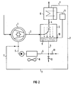
- FIG 2
- eine zweite Ausführungsform, die gegenüber einer Flüssigkeitsringpumpe nach FIG 1 zusätzlich einen Luftkühler aufweist,
- FIG 3
- eine dritte Ausführungsform der erfindungsgemäßen Flüssigkeitsringpumpe mit einer in den Separator mündenden Gasringpumpe.
- FIG. 1
- a first embodiment of the liquid ring pump according to the invention with a heat exchanger,
- FIG 2
- 1 shows a second embodiment which additionally has an air cooler compared to a liquid ring pump according to FIG. 1,
- FIG 3
- a third embodiment of the liquid ring pump according to the invention with a gas ring pump opening into the separator.
In den FIG 1 bis 3 ist mit 1 eine Flüssigkeitsringpumpe bezeichnet, der über eine Verbindungsleitung 2 ein Separator 3 nachgeschaltet ist. Der Separator 3 weist eine Abluftleitung 4 auf, die in die Atmosphäre mündet. Weiterhin ist der Separator 3 über eine Rücklaufleitung 5 mit der Flüssigkeitsringpumpe 1 verbunden.1 to 3, 1 denotes a liquid ring pump, which is followed by a
Bei den in den FIG 1 und 2 dargestellten Ausführungsbeispielen ist in der Abluftleitung 4 ein Wärmetauscher 6 angeordnet, der über eine Rohrleitung 7 an die Rücklaufleitung 5 geschaltet ist.In the exemplary embodiments shown in FIGS. 1 and 2, a heat exchanger 6 is arranged in the exhaust air line 4 and is connected to the
Der Separator 3 dient zusammen mit dem Wärmetauscher 6 der Rückgewinnung von Betriebsflüssigkeit, die nach der Verdichtung des zu fördernden Gases teilweise mit diesem aus der Flüssigkeitsringpumpe 1 hinausgedrückt wird. Die Zurückgewonnene Betriebsflüssigkeit aus dem Separator 3 wird über die Rücklaufleitung 5 sowie aus dem Wärmetauscher 6 über die Rohrleitung 7 in die Flüssigkeitsringpumpe 1 zurückgeführt.The
Eine besonders gute Kühlung der Betriebsflüssigkeit wird bei dem in FIG 2 dargestellten Ausführungsbeispiel durch einen in der Rücklaufleitung 5 angeordneten Luftkühler 8 erreicht.In the exemplary embodiment shown in FIG. 2, particularly good cooling of the operating fluid is achieved by an air cooler 8 arranged in the
Das Niveau des von der Betriebsflüssigkeit im Separator 3 gebildeten Kondensats 9 wird durch einen Niveausensor 10 erfaßt, der vorzugsweise ein Peltier-Element umfaßt. Der Niveausensor 10 ist funktionell Teil eines Reglers 11. Der Regler 11 regelt deshalb in Abhängigkeit vom Niveau des Kondensats 9 die Kühlleistung des Wärmetauschers 6. Die Regelung erfolgt hierbei derart, daß bei sinkendem Kondensatstand die Kühlleistung erhöht wird und bei steigendem Kondensatstand die Kühlleistung verringert wird. Bei sinkendem Kondensatstand erhöht sich dadurch der Kondensatgewinn und bei hohem Niveau des Kondensats die Austragung durch Verdunsten. Üblicherweise wird mit Wasser als Betriebsflüssigkeit gearbeitet. Um Luft als Fördergas zu fördern, die auf der Ansaugseite der Flüssigkeitsringpumpe 1 beispielsweise 20 °C und eine relative Feuchte von 50 % aufweist, und um eine Menge von 2 bis 2,5 kg pro Sekunde zu fördern, ist vom Wärmetauscher 6 eine Menge an Betriebsflüssigkeit in der Größenordnung von 450 kg pro Stunde zu bewältigen.The level of the
Um einen überlagerten Betrieb zu ermögilchen, kann man in der Rücklaufleitung 5 zwischen Separator 3 und Luftkühler 8 ein Ablaßventil 12 und/oder ein Einlaßventil 13 vorsehen.In order to enable a superimposed operation, a
Bei dem in FIG 3 dargestellten Ausführungsbeispiel ist an dem Separator 3 ein Gasringverdichter 14 angeordnet. Der Gasringverdichter 14 bläst Luft aus der Atmosphäre in den Separator 3. Die Luft wird hierbei durch das Kondensat 9 hindurch in den Separator 3 eingeführt. Man erhält dadurch einen besonders hohen Sättigungsgrad der eingebrachten Luft. Die zur Sättigung der Luft mit Wasser notwendige Verdampfungswärme wird dem Wasser entzogen, das dadurch gekühlt wird. Der hierbei auftretende Wasserverlust führt zu einem Absinken des Kondensats 9. In vorteilhafter Weise wird das Absinken des Kondensats 9 über einen Niveausensor 15 erfaßt, der als Schwimmerschalter ausgebildet ist und selbsttätig eine wasserführende Versorgungsleitung 16 zuschaltet. Die Zuschaltung der Versorgungsleitung 16 kann hierbei wiederum über ein Einlaßventil 17 erfolgen.In the embodiment shown in FIG 3, a
Claims (15)
- Liquid ring pump (1) having a separator (3) connected downstream thereof for recovering the operating liquid, which separator has an exhaust air line (4) and also a return line (5) leading back to the liquid ring pump (1), characterised in that connected into the exhaust air line (4) of the separator (3) there is a heat exchanger (6) which can be controlled in terms of its cooling capacity by means of a level sensor (10, 15) as a function of the level of the condensate (9), which has accumulated in the separator (3), in such a way that with falling level of condensate the cooling capacity is increased and with rising level of condensate the cooling capacity is reduced.
- Liquid ring pump (1) according to claim 1, characterised in that an outlet valve (12) and/or an inlet valve (13) are/is arranged in the return line (5).
- Liquid ring pump (1) according to claim 1 or 2, with a further heat exchanger (8) being connected into the return line (5), characterised in that this heat exchanger is formed as an air cooler (8).
- Liquid ring pump (1) having a separator (3) connected downstream thereof for recovering the operating liquid, which separator has an exhaust air line (4) and also a return line (5) leading back to the liquid ring pump (1), characterised in that arranged at the separator (3) there is at least one gas ring compressor (14) or ventilator compressing air into said separator.
- Liquid ring pump according to one or several of the claims 1 to 3, characterised in that arranged at the separator (3) there is at least one gas ring compressor (14) or ventilator compressing air into said separator.
- Liquid ring pump (1) according to claim 4 or 5, characterised in that the air is introduced into the separator (3) through the condensate (9).
- Liquid ring pump (1) according to one of the claims 4 to 6, characterised in that the air is introduced into the separator (3) above the condensate (9).
- Liquid ring pump (1) according to one of the claims 3 to 7, characterised in that an outlet valve (12) and/or an inlet valve (13) are/is arranged in the return line (5) between separator (3) and air cooler (8).
- Liquid ring pump (1) according to one of the claims 3 to 8, characterised in that an outlet valve (12) and/or an inlet valve (13), which is connected to a supply line for the operating liquid, are/is arranged in the return line (5) between separator (3) and air cooler (8).
- Liquid ring pump (1) according to one or several of the claims 1 to 9, characterised in that arranged at the separator (3) there is an inlet valve (17) which is connected to a supply line (16) for the operating liquid.
- Liquid ring pump (1) according to one of the claims 8 to 10, characterised in that the inlet valve (13, 17) and/or the outlet valve (12) can be controlled as a function of the level of condensate in the separator (3).
- Liquid ring pump (1) according to claim 11, characterised in that the control is effected by means of a level sensor (10, 15) in such a way that with a level of condensate falling below a preselectable lower limiting value the inlet valve (13, 17) is opened and with a level of condensate rising above a preselectable upper limiting value the outlet valve (12) is opened.
- Liquid ring pump (1) according to claim 12, characterised in that the level sensor is formed as a float switch (15).
- Liquid ring pump (1) according to one of the claims 1 to 12, characterised in that the level sensor comprises a Peltier element (10).
- Liquid ring pump (1) according to one of the claims 1 to 14, characterised in that connected upstream of the latter there is at least one gas ring pump.
Priority Applications (2)
| Application Number | Priority Date | Filing Date | Title |
|---|---|---|---|
| DE59006448T DE59006448D1 (en) | 1990-11-23 | 1990-11-23 | Liquid ring pump. |
| EP19900122405 EP0486726B1 (en) | 1990-11-23 | 1990-11-23 | Liquid ring pump |
Applications Claiming Priority (1)
| Application Number | Priority Date | Filing Date | Title |
|---|---|---|---|
| EP19900122405 EP0486726B1 (en) | 1990-11-23 | 1990-11-23 | Liquid ring pump |
Publications (2)
| Publication Number | Publication Date |
|---|---|
| EP0486726A1 EP0486726A1 (en) | 1992-05-27 |
| EP0486726B1 true EP0486726B1 (en) | 1994-07-13 |
Family
ID=8204745
Family Applications (1)
| Application Number | Title | Priority Date | Filing Date |
|---|---|---|---|
| EP19900122405 Expired - Lifetime EP0486726B1 (en) | 1990-11-23 | 1990-11-23 | Liquid ring pump |
Country Status (2)
| Country | Link |
|---|---|
| EP (1) | EP0486726B1 (en) |
| DE (1) | DE59006448D1 (en) |
Cited By (2)
| Publication number | Priority date | Publication date | Assignee | Title |
|---|---|---|---|---|
| US8034144B2 (en) | 1999-02-26 | 2011-10-11 | Donaldson Company, Inc. | Filter arrangement; sealing system; and methods |
| CN110418891A (en) * | 2017-02-24 | 2019-11-05 | 佶缔纳士机械有限公司 | Pumping system including controller |
Families Citing this family (9)
| Publication number | Priority date | Publication date | Assignee | Title |
|---|---|---|---|---|
| ES2102731T3 (en) * | 1993-08-11 | 1997-08-01 | Siemens Ag | MECHANICAL COMPRESSION INSTALLATION. |
| FR2709428B1 (en) * | 1993-09-01 | 1995-09-29 | Cit Alcatel | Installation for the continuous purification of a solvent. |
| ES2106611T3 (en) * | 1994-12-06 | 1997-11-01 | Siemens Ag | COMPRESSOR GROUP. |
| DE29714851U1 (en) * | 1997-08-19 | 1997-10-23 | Siemens Ag | Liquid ring pump unit |
| FI110537B (en) * | 2001-06-29 | 2003-02-14 | Evac Int Oy | The vacuum sewer system |
| US7762789B2 (en) * | 2007-11-12 | 2010-07-27 | Ingersoll-Rand Company | Compressor with flow control sensor |
| CN105822577B (en) * | 2015-01-06 | 2018-01-09 | 中国石化工程建设有限公司 | A kind of pendular ring pump/compressor system and the method for preventing overload |
| CN108223375A (en) * | 2017-11-23 | 2018-06-29 | 中材节能股份有限公司 | A kind of integration pendular ring vacuum extractor |
| CN112344215A (en) * | 2020-09-18 | 2021-02-09 | 南通新金丰皮革机械有限公司 | Vacuum system liquid feeding device for leather |
Family Cites Families (3)
| Publication number | Priority date | Publication date | Assignee | Title |
|---|---|---|---|---|
| US3785755A (en) * | 1971-11-22 | 1974-01-15 | Rogers Machinery Co Inc | Air compressor system |
| FR2374539A1 (en) * | 1976-12-15 | 1978-07-13 | Air Ind | WATER VAPOR COMPRESSION PROCESS, AND THERMAL CIRCUITS FOR ITS IMPLEMENTATION |
| FR2553500B1 (en) * | 1983-10-14 | 1986-01-03 | Sihi Pompes | METHOD AND DEVICE FOR RECOVERING HYDROCARBON VAPORS |
-
1990
- 1990-11-23 DE DE59006448T patent/DE59006448D1/en not_active Expired - Fee Related
- 1990-11-23 EP EP19900122405 patent/EP0486726B1/en not_active Expired - Lifetime
Cited By (3)
| Publication number | Priority date | Publication date | Assignee | Title |
|---|---|---|---|---|
| US8034144B2 (en) | 1999-02-26 | 2011-10-11 | Donaldson Company, Inc. | Filter arrangement; sealing system; and methods |
| US8246708B2 (en) | 1999-02-26 | 2012-08-21 | Donaldson Company, Inc. | Filter arrangement; sealing system; and methods |
| CN110418891A (en) * | 2017-02-24 | 2019-11-05 | 佶缔纳士机械有限公司 | Pumping system including controller |
Also Published As
| Publication number | Publication date |
|---|---|
| DE59006448D1 (en) | 1994-08-18 |
| EP0486726A1 (en) | 1992-05-27 |
Similar Documents
| Publication | Publication Date | Title |
|---|---|---|
| DE69907954T2 (en) | GAS BOOSTERS | |
| EP0486726B1 (en) | Liquid ring pump | |
| CH695869A5 (en) | Multilevel, switchable between load and idling compressor. | |
| DE4115905A1 (en) | REFRIGERATION CIRCUIT ARRANGEMENT WITH A COMPRESSOR DEVICE HAVING TWO SIMULTANEOUSLY DRIVED COMPRESSOR UNITS | |
| DE3204784A1 (en) | LIQUID RING VACUUM PUMP WITH UPstream COMPRESSOR | |
| EP0848981B1 (en) | Pressure swing adsorption plant to separate oxygen from the air and process to operate the same | |
| DE2231921A1 (en) | STEAM CONDENSATION PLANT WITH TWO-STAGE AIR CONDENSATION | |
| DE3316646A1 (en) | CENTRIFUGAL SAVING DEVICE FOR REFRIGERATING MACHINE OR THE LIKE MACHINE EQUIPPED WITH THIS DEVICE | |
| DE10048439A1 (en) | Steam turbine plant and method for operating a steam turbine plant | |
| EP0847791A1 (en) | Pressure swing adsorption plant to seperate oxygen from the air and process to operate the same | |
| EP0638723B1 (en) | Mechanical compression plant | |
| DE2061917C3 (en) | Cooling device with a flow control valve between the condenser and the metering device | |
| CH646774A5 (en) | HEAT PUMP. | |
| DE968232C (en) | Liquid ring vacuum pump with upstream ejector | |
| WO2003083307A1 (en) | Pump device, method for operating a pump device and the use thereof in a steam turbine installation | |
| EP0437637A1 (en) | Liquid ring pump | |
| DE3511421C2 (en) | ||
| CH218967A (en) | Process for the lubrication of rotary piston machines working as compressors or vacuum pumps. | |
| DE2603968A1 (en) | Motor vehicle air conditioner refrigerator regulator - supplies bled refrigerant vapour to compressor at constant pressure preventing overheating | |
| DE2113038C3 (en) | Measurement and control arrangement for the condensate-free operation of gas compressors | |
| DE10358428A1 (en) | Refrigerating plant for a supercritical operating method with an economizer has a condenser with a coolant like carbon dioxide with its condensing pressure in a supercritical range | |
| DE2503873B2 (en) | Liquid ring pump unit | |
| DE1926395A1 (en) | Ventilation device for exhaust steam condensers of steam turbines | |
| EP0802329A2 (en) | Breathing device for a storage tank | |
| DE1428047A1 (en) | Method and device for the condensation-free operation of multi-stage turbo compressors with intermediate cooling |
Legal Events
| Date | Code | Title | Description |
|---|---|---|---|
| PUAI | Public reference made under article 153(3) epc to a published international application that has entered the european phase |
Free format text: ORIGINAL CODE: 0009012 |
|
| 17P | Request for examination filed |
Effective date: 19901205 |
|
| AK | Designated contracting states |
Kind code of ref document: A1 Designated state(s): BE DE FR IT NL |
|
| 17Q | First examination report despatched |
Effective date: 19931019 |
|
| GRAA | (expected) grant |
Free format text: ORIGINAL CODE: 0009210 |
|
| AK | Designated contracting states |
Kind code of ref document: B1 Designated state(s): BE DE FR IT NL |
|
| REF | Corresponds to: |
Ref document number: 59006448 Country of ref document: DE Date of ref document: 19940818 |
|
| ITF | It: translation for a ep patent filed |
Owner name: STUDIO JAUMANN |
|
| ET | Fr: translation filed | ||
| PLBE | No opposition filed within time limit |
Free format text: ORIGINAL CODE: 0009261 |
|
| STAA | Information on the status of an ep patent application or granted ep patent |
Free format text: STATUS: NO OPPOSITION FILED WITHIN TIME LIMIT |
|
| 26N | No opposition filed | ||
| PGFP | Annual fee paid to national office [announced via postgrant information from national office to epo] |
Ref country code: BE Payment date: 19961114 Year of fee payment: 7 |
|
| PGFP | Annual fee paid to national office [announced via postgrant information from national office to epo] |
Ref country code: NL Payment date: 19961118 Year of fee payment: 7 |
|
| PGFP | Annual fee paid to national office [announced via postgrant information from national office to epo] |
Ref country code: FR Payment date: 19961129 Year of fee payment: 7 |
|
| PGFP | Annual fee paid to national office [announced via postgrant information from national office to epo] |
Ref country code: DE Payment date: 19970121 Year of fee payment: 7 |
|
| PG25 | Lapsed in a contracting state [announced via postgrant information from national office to epo] |
Ref country code: FR Free format text: THE PATENT HAS BEEN ANNULLED BY A DECISION OF A NATIONAL AUTHORITY Effective date: 19971130 Ref country code: BE Free format text: LAPSE BECAUSE OF NON-PAYMENT OF DUE FEES Effective date: 19971130 |
|
| BERE | Be: lapsed |
Owner name: SIEMENS A.G. Effective date: 19971130 |
|
| PG25 | Lapsed in a contracting state [announced via postgrant information from national office to epo] |
Ref country code: NL Free format text: LAPSE BECAUSE OF NON-PAYMENT OF DUE FEES Effective date: 19980601 |
|
| PG25 | Lapsed in a contracting state [announced via postgrant information from national office to epo] |
Ref country code: DE Free format text: LAPSE BECAUSE OF NON-PAYMENT OF DUE FEES Effective date: 19980801 |
|
| NLV4 | Nl: lapsed or anulled due to non-payment of the annual fee |
Effective date: 19980601 |
|
| REG | Reference to a national code |
Ref country code: FR Ref legal event code: ST |
|
| PG25 | Lapsed in a contracting state [announced via postgrant information from national office to epo] |
Ref country code: IT Free format text: LAPSE BECAUSE OF NON-PAYMENT OF DUE FEES;WARNING: LAPSES OF ITALIAN PATENTS WITH EFFECTIVE DATE BEFORE 2007 MAY HAVE OCCURRED AT ANY TIME BEFORE 2007. THE CORRECT EFFECTIVE DATE MAY BE DIFFERENT FROM THE ONE RECORDED. Effective date: 20051123 |