EP0486413A1 - Erntemaschine, besonders Mähmaschine, die leicht von einer Arbeitstellung in eine Transportstellung versetzt werden kann - Google Patents
Erntemaschine, besonders Mähmaschine, die leicht von einer Arbeitstellung in eine Transportstellung versetzt werden kann Download PDFInfo
- Publication number
- EP0486413A1 EP0486413A1 EP91440088A EP91440088A EP0486413A1 EP 0486413 A1 EP0486413 A1 EP 0486413A1 EP 91440088 A EP91440088 A EP 91440088A EP 91440088 A EP91440088 A EP 91440088A EP 0486413 A1 EP0486413 A1 EP 0486413A1
- Authority
- EP
- European Patent Office
- Prior art keywords
- harvesting machine
- machine according
- axis
- articulation
- wheel
- Prior art date
- Legal status (The legal status is an assumption and is not a legal conclusion. Google has not performed a legal analysis and makes no representation as to the accuracy of the status listed.)
- Granted
Links
Images


Classifications
-
- A—HUMAN NECESSITIES
- A01—AGRICULTURE; FORESTRY; ANIMAL HUSBANDRY; HUNTING; TRAPPING; FISHING
- A01B—SOIL WORKING IN AGRICULTURE OR FORESTRY; PARTS, DETAILS, OR ACCESSORIES OF AGRICULTURAL MACHINES OR IMPLEMENTS, IN GENERAL
- A01B73/00—Means or arrangements to facilitate transportation of agricultural machines or implements, e.g. folding frames to reduce overall width
- A01B73/005—Means or arrangements to facilitate transportation of agricultural machines or implements, e.g. folding frames to reduce overall width for endwise transportation, i.e. the direction of transport being substantially perpendicular to the direction of agricultural operation
-
- Y—GENERAL TAGGING OF NEW TECHNOLOGICAL DEVELOPMENTS; GENERAL TAGGING OF CROSS-SECTIONAL TECHNOLOGIES SPANNING OVER SEVERAL SECTIONS OF THE IPC; TECHNICAL SUBJECTS COVERED BY FORMER USPC CROSS-REFERENCE ART COLLECTIONS [XRACs] AND DIGESTS
- Y10—TECHNICAL SUBJECTS COVERED BY FORMER USPC
- Y10S—TECHNICAL SUBJECTS COVERED BY FORMER USPC CROSS-REFERENCE ART COLLECTIONS [XRACs] AND DIGESTS
- Y10S56/00—Harvesters
- Y10S56/14—Hitch
Definitions
- connection device for laterally coupling a corn harvester to the rear three-point hitch of a tractor.
- This connection device comprises a connection piece, rigidly connected to the tractor, as well as a beam which is linked, at one of its ends, to said connection piece by means of a vertical axis. At its other end, the spar rests on the ground by means of a wheel pivotally mounted about a vertical axis.
- the pivoting of the beam relative to the connecting piece is locked by means of a locking device, while the wheel is capable of pivoting around its vertical axis linking it to said beam.
- the beam is capable of pivoting about the vertical axis linking it to the connection piece, while the pivoting of the wheel is locked by means of a pin.
- the beam fixed with respect to the connecting piece itself rigidly connected to the tractor, secures the beam with the tractor, which considerably simplifies the maneuvers.
- the object of the present invention is to remedy this drawback while retaining the double advantage of making little use of the coupling device of the motor vehicle and of exhibiting good maneuverability of the machine, both at work and during transport.
- the harvesting machine further comprises an orientation member used to orient the wheel in the direction of transport.
- this orientation member the orientation of the wheel for transport is carried out in a simple and rapid manner, while allowing the pivoting of the wheel at work around its axis linking it to the body.
- the axis of the first articulation prefferably be at least substantially parallel to the axis of the second articulation.
- connection device to comprise an additional articulation with an axis directed at least approximately orthogonally to the axis of the second articulation and to the longitudinal axis of the body.
- the additional articulation extends between the body and the second articulation.
- the axis of the second articulation and the axis of the additional articulation can be concurrent.
- the pivoting of the body from its transport position towards its working position, around the axis of the second articulation is carried out under the action of a member maneuver.
- This operating member constitutes, at least in part, the second locking device which can condemn the pivoting of the body around the axis of the second articulation.
- connection means consist of a three-point hitching structure coupling intended to be linked to the three points of the coupling device of a motor vehicle.
- the wheel meanwhile, extends in its working position behind at least part of the working members.
- the passage of the wheel from a working position to a transport position is effected by means of a positioning element. This positions the wheel, for transport, at least substantially in the longitudinal extension of the body.
- the positioning element may consist of an arm at one end of which the wheel is linked by means of the first articulation, this arm being itself linked to the body by means of a third articulation with an axis directed towards the top.
- the axes of the first, second and third joints may be at least substantially parallel to one another.
- the axis of the third articulation, linking the positioning arm to the body may extend, in top view, behind the longitudinal axis of said body when the latter is in its working position.
- the positioning arm may form, when viewed from above, an acute angle with the longitudinal axis of the body when the latter is in the transport position and an angle at least substantially straight with said longitudinal axis of the body when the latter is in working position.
- a first end of travel member is provided to act directly or indirectly on the control member of the first inverter and a second end of travel member to act directly or indirectly on the control member of the second inverter.
- each inverter of the control device may be, at least in part, electrical, mechanical, hydraulic, etc. .
- the first end-of-travel member can, when the body arrives in its working position, act on the control member of the first inverter and place said first inverter in its second position.
- the second end-of-travel member no longer acts on the control member of the second inverter, and the second inverter then moves to its second position.
- the second end-of-stroke member may, in certain embodiments, be linked to the positioning arm.
- a compensation member is provided allowing the positioning arm to continue its movement towards the transport position after the second end-of-travel member is in contact with the control member of the second inverter.
- This compensating member can be constituted by an elastically deformable member arranged between the second end of stroke member and the positioning arm.
- the orientation member is part of the first locking device intended to condemn the pivoting of the wheel around the axis of the first articulation.
- the orientation member of the wheel may comprise a lever, pivoting about a pivot axis, which has two stops extending on either side of the pivot axis and intended to come into contact with a body organ under the action of a positioning organ.
- the contact between the pivoting lever and the body member can be achieved by means of a roller rotating about an axis at least substantially parallel to the pivot axis of the pivoting lever.
- the pivot axis of the pivoting lever can extend at least substantially in the same direction as the axis of the first articulation.
- the orientation member of the wheel is intended to come into contact with an organ of the body when said arm arrives in its position of transport.
- the pivoting lever can be linked to the positioning arm in the vicinity of the third articulation connecting the positioning arm to the body.
- This pivoting lever also comprises an arm to which a connecting rod is articulated, itself articulated at an orientation arm which is linked to a pin whose longitudinal axis defines the axis of the first articulation.
- the operating member is a jack, the latter being able, as said above, to be electric, pneumatic, hydraulic, etc.
- the actuating cylinder may more precisely be a double rod cylinder or equivalent.
- Each rod thereof can be linked to its respective end, extending outside the cylinder, by means of connection, while the cylinder can be in drive connection with the body. Therefore, the cylinder can translate relative to the connecting means and drive the body with which said cylinder is connected.
- the drive link between the cylinder of the double-rod actuating cylinder and the body may be produced by means of a rack linked to said cylinder and meshing with a circular toothed sector linked to the body and centered on the axis of the second articulation. .
- the actuating cylinder is a hydraulic cylinder.
- the second inverter may include a loop which, in the first position of said second inverter, connects the two chambers of the actuating cylinder, thereby allowing the body to pivot relative to the connecting means around the axis of the second joint.
- the second locking device may include a pressure limiter arranged in parallel in the circuit of the actuating cylinder by means of two pipes.
- first end-of-travel member which acts on the control member of the first inverter, is linked to the cylinder of the actuating cylinder.
- the positioning member is made to also consist of at least one hydraulic cylinder.
- the invention finds a particularly advantageous application in the field of mowers with or without organs for treating the cut product.
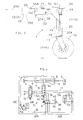
- FIGs 1 to 3 we see a mower (1) according to the invention. This is coupled to an agricultural tractor (2).
- the mower (1) consists of a body (3) and a coupling structure (4).
- the coupling structure (4) is intended to be linked, at its front part, to the three-point coupling (5) of the agricultural tractor (2).
- the body (3) for its part, is linked to the coupling structure (4) by means of a connection device (6) which in particular comprises an articulation (7).
- This articulation (7) allows the body (3) to pivot about a geometric axis (7A) ( Figure 2) at least substantially vertical.
- the angular position of the body (3) relative to the hitching structure (4) can be changed by pivoting the body (3) around the vertical axis (7A) of the connecting device (6).
- the locking device (8A) comprises on the one hand the actuating cylinder (8) which is a double rod hydraulic cylinder (9, 9A), and on the other hand a control device (10) - the description of which will be made later - which supplies the said in particular cylinder (8).
- Each rod (9, 9A) of this jack (8) is rigidly connected at its respective end, extending outside the cylinder (11), to the coupling structure (4), so as to allow the cylinder ( 11) of said jack (8) to translate horizontally under the action of the oil which feeds it.
- a rack (12) which meshes with a cylindrical toothed wheel (13) whose axis of rotation coincides with the vertical axis (7A) of the connecting device (6).
- the toothed wheel (13) which rotates around the vertical axis (7A) is linked in rotation with the body (3) of the mower (1). Therefore, the body (3) can extend, by pivoting about the vertical axis (7A) produced under the action of the actuating cylinder (8), either in a working position (203) next to the tractor (2) ( Figures 1 and 2), or in a transport position (103) in the extension of the tractor (2) ( Figure 5).
- the body (3) of the mower (1) comprises a harvesting mechanism (14) suspended from a frame (15).
- the chassis (15) is supported on the ground by means of a wheel (16) which rolls between the wings of a yoke (17).
- a positioning arm (19) in the form of a hollow bracket comprises, in its vertical part, the pin (18).
- the connection of the trunnion (18) with the positioning arm (19) is produced by an articulation (20) of the pivot type whose geometric axis (20A) is at least substantially vertical.
- the positioning arm (19) is connected to the chassis (15) by means of a hinge (21). This is also of the pivot type and its geometric axis (21A) extends at least substantially parallel to the geometric axis (20A) of the previous pivot link (20).
- the angular position of the positioning arm (19) provided with the wheel (16) can be modified by pivoting said arm (19) relative to the chassis (15) around the geometric axis (21A) of the joint (21).
- the positioning arm (19) allows the wheel (16) to turn partially around the end of the harvesting mechanism (14) remote from the tractor (2) to place said wheel (16) either in the transport position (116) ( Figure 5), either in the working position (216) ( Figure 1), in which it extends behind the center of gravity of the body (3) taking into account the direction of advance (23 or 23A ) corresponding.
- the positioning arm (19) aligns at least substantially the wheel (16) with the center of gravity of the body (3) and the vertical axis (7A ) of the connecting device (6), and that in its working position (219), the positioning arm (19) places the wheel (16) behind the cutting members (24) of the mower (1).
- the positioning in the desired position is carried out by means of a hydraulic positioning cylinder (22) which extends between the frame (15) and the positioning arm (19).
- the supply of the actuator (22) and the maintenance of the arm (19) in the desired angular position are controlled, as for the actuating actuator (8), by the control device (10).
- Figures 1, 2 and 5 also very precisely show the shape of the frame (15).
- This essentially consists of a beam (25) which extends, at work, transverse to the direction of advance (23A) at work and, during transport, parallel to the direction of advance (23 ) during transport. It is linked to the coupling structure (4) by means of the connection device (6).
- the connection device (6) In addition to the articulation (7) allowing the body (3) and the chassis (15) to pivot around its vertical axis (7A) respectively, the connection device (6) also has an additional articulation (26) arranged between the previous joint (7) of the connecting device (6) and the body (3).
- the geometric axis (26A) thereof is at least substantially horizontal and extends orthogonally to the longitudinal axis (3A) of the body (3) to allow the chassis (15) to pivot relative to the structure of hitch (4).
- this horizontal axis (26A) is concurrent with the vertical axis (7A) of the connecting device (6).
- the chassis (15) also includes a console (25A). This extends transversely to the longitudinal axis of the beam (25) of the chassis (15) and is linked to the longitudinal end of the beam (25), opposite the connection device (6).
- the console (25A) of the chassis (15) comprises, at its free end opposite the beam (25), the articulation (21) connecting the positioning arm (19) to the chassis (15).
- the positioning arm (19) when in its transport position (119), to form an acute angle (a) with the longitudinal axis (3A) of the body (3 ), while in its working position (219), the positioning arm (19) forms with said longitudinal axis (3A) an angle (p) at least substantially straight.
- the harvesting mechanism (14), for its part, is known to those skilled in the art and extends under the chassis (15) in a direction transverse to the direction of advance (23A) at work. It essentially consists of a cutter bar (27) fitted with the cutting members (24), a support structure (28) (FIG. 2) to which are attached processing members (29), and an inlet housing (30).
- the inlet casing (30) is linked to the longitudinal end of the support structure (28) directed towards the coupling structure (4) and is intended to drive the cutting members (24) and the processing members (29).
- Above the cutting members (24) extends at least substantially parallel to the cutter bar (27), the support structure (28) supporting the processing members (29). These are placed behind the cutting members (24) for the treatment of the product cut by the latter.
- the supporting structure (28) comprises protective members (37) ( Figures 1 and 5) which extend around the cutter bar (27) and which are intended to protect the user or persons in the vicinity in the vicinity.
- a suspension arm (31) suspends the harvesting mechanism (14) from the chassis (15).
- the suspension arm (31) is arranged above the harvesting mechanism (14) and extends in top view at least substantially parallel to the beam (25) of the chassis (15) and in the vicinity of the latter.
- the suspension arm (31) is linked to the support structure (28) of the harvesting mechanism (14), in the middle part thereof, by means of a joint (32 ) pivot type.
- the geometric axis of this articulation (32) extends at least substantially in a vertical plane directed in the direction of advance (23A) at work and containing the center of the masses of the harvesting mechanism (14). Moreover, said geometric axis is at least substantially directed in the direction of advance (23A) at work.
- the suspension arm (31) is linked to the beam (25) of the chassis (15) by means of a joint (33) arranged near the joint (7) with a vertical axis (7A ) connecting the chassis (15) to the coupling structure (4).
- This articulation (33) is of the pivot type and its geometric axis is also directed at least substantially in the direction of advance (23A) at work. Therefore, the suspension arm (31) allows only a movement of the harvesting mechanism (14) in height, as well as a pivoting of said harvesting mechanism (14) relative to the chassis (15) around a direction at less substantially parallel to the direction of advance (23A) at work. Thanks to this suspension arm (31), the harvesting mechanism (14) can adapt to the configurations of the terrain and pass over obstacles that it may present.
- the suspension arm (31) is provided with a roller (34).
- the latter is arranged between the two articulations (32, 33) of the suspension arm (31) and its axis of rotation at least substantially intersects the geometric axis of the articulation (33) connecting the suspension arm (31) to the chassis (15).
- the roller (34) extends more precisely between the suspension arm (31) and the beam (25) of the chassis (15), so as to bear, by means of a support (35) against said beam (25). Thanks to this roller (34), the force which opposes the sliding of the harvesting mechanism (14) on the ground is transmitted, at least in part, by the roller (34) to the chassis (15). Therefore, the suspension arm (31) can follow the movements in height of the harvesting mechanism (14), the articulation (33) being relieved in any position of said arm (31).
- the support (35) is arranged in the vicinity of the middle part of the suspension arm (31) and has four flat parts (35A, 35B, 35C, 35D), the first of which (35A) is linked to the anterior lateral face of the beam (25) of the chassis (15) and against which the roller (34) bears.
- the second part (35B) of this support (35) extends approximately parallel under the suspension arm (31).
- the fourth part (35D) meanwhile, extends horizontally and is linked to the upper face of the beam (25) of the chassis (15). Therefore, during movements in height of the harvesting mechanism (14), the suspension arm (31) moves inside the support (35), while the roller (34) bears against the first part (35A) of said support (35).
- the harvesting mechanism (14) is driven from the PTO (not shown) of the tractor (2), which attacks, via a telescopic shaft with universal joints (38), the input shaft (39) ( Figure 2) of a motion transmission device (40).
- the output shaft (41) of the motion transmission device (40) which pivots with the body (3) around the vertical axis (7A) of the joint (7), is always oriented at least substantially parallel to the longitudinal axis (3A) of the body (3) and drives, via another telescopic shaft with universal joints (42), the input shaft (43) of the input housing (30) of the harvesting mechanism (14).
- the input shaft (43) is also oriented at least substantially parallel to the longitudinal axis (3A) of the body (3).
- the mower (1) further comprises a lifting device (44) of the harvesting mechanism (14).
- This lifting device (44) mainly consists of a lifting cylinder (45) whose cylinder (46) is linked to the chassis (15) and whose rod (47) is linked to a chain (48).
- This chain (48) is partially wound on a wheel (49) ( Figure 2), guided in rotation in the chassis (15), and is connected at its end remote from the lifting cylinder (45) to the suspension arm (31 ).
- the chain (48) is relaxed and can deform freely, so that the lifting device (44) does not hinder the movement in height of the harvesting mechanism (14) relative to the chassis (15).
- the positioning arm (19) supports a locking device (50) of the wheel (16) which comprises, in this embodiment, a member for orientation and locking (51).
- the latter is a pivoting lever (52) linked to the positioning arm (19) by means of an articulation (53) arranged in the vicinity of the articulation (21) connecting the positioning arm (19) to the chassis (15).
- the geometric axis (53A) of this articulation (53) extends at least substantially parallel to the axis (20A) of the articulation (20) connecting the wheel (16) to the positioning arm (19).
- the pivoting lever (52) On either side of the articulation (53), the pivoting lever (52) has two stops (54, 54A) which are intended, when the positioning arm (19) returns to its transport position (119), coming into contact with the console (25A) of the chassis (15).
- the console (25A) of the chassis (15) is provided with a roller (55) rotating around a geometric axis (55A) at least substantially parallel to the pivot axis (53A) of the pivoting lever ( 52), and with which one (54) of the stops (54, 54A) of the pivoting lever (53) comes into contact.
- the pivoting lever (52) comprises an arm (56) to which a connecting rod (57) is linked by means of a hinge (58) with a geometric axis parallel to the geometric axis (53A) of the articulation (53).
- the connecting rod (57) extends approximately parallel to the horizontal part of the positioning arm (19) and is linked to an orientation arm (59) by means of a joint (60) geometric axis also parallel to the geometric axis (53A) of the joint (53).
- This orientation arm (59) is rigidly connected, but in a removable manner, to the journal (18) which allows the pivoting of the wheel (16).
- the angular position of the wheel (16) is a function of the angular position of the stops (54, 54A) of the pivoting lever (52), by means of the arm (56) of the pivoting lever (52), of the connecting rod (57) and of the orientation arm (59).
- the stops (54, 54A) of the pivoting lever (52) are oriented against the console (25A) of the chassis (15) and thus places the wheel (16) in the direction of advance (23) during transport ( Figures 5 and 13).
- FIG. 4 shows the hydraulic wiring of the control device (10). It can be seen in particular in FIG. 4 that the oil is brought to the actuating cylinder (8) by two pairs of successive lines (61, 61A, 61 B, 61 C) which constitute the supply circuit for the actuating cylinder (8).
- the oil which feeds this circuit (61, 61A, 61 B, 61C) is distributed by the control device (10).
- This comprises two reversers (62, 63), the first (62) of which is linked to the coupling structure (4) and the second (63) of which is linked to the body (3) of the machine (1).
- Each inverter (62, 63) is controlled by a corresponding control member (64, 65) represented by a pusher in the example described.
- the first reverser (62) which is linked to the coupling structure (4), extends more precisely in the vicinity of the actuating cylinder (8).
- the second reverser (63), meanwhile, is linked to the console (25A) of the chassis (15), so that its control member (65) can, in particular during transport, be actuated by a limit switch member (66) linked to the positioning arm (19) ( Figure 13).
- the end of travel member (66) is rigidly fixed to the longitudinal end of a rod (67) directed, during transport, to the corresponding control member (65).
- This rod (67) is linked to the positioning arm (19) by means of a cylindrical articulation (68) of the sliding pivot type allowing in particular a translation of said rod (67) relative to the positioning arm (19).
- a spring (69), arranged between the positioning arm (19) and the end of travel member (66) allows, by elastically deforming, the positioning arm (19) to continue its displacement from its intermediate position (319 ) to its transport position (119) after the end of travel member (66) is in contact with the control member (65) of the second inverter (63).
- the control member (65) of the second inverter (63) is not actuated by the limit switch member (66) and, as said above, the wheel (16) can pivot around the geometric axis (20A). If the control member (65) of the second inverter (63) is not actuated (FIGS. 8 to 11), the oil is distributed to the circuit (61, 61A, 61 B, 61 C) of the actuating cylinder ( 8) described previously.
- the oil is distributed by the second inverter (63) to the circuit of the positioning cylinder (22).
- This circuit comprises in particular two pairs of lines (70, 70A, 71.71A) which convey the oil between the second reverser (63) and the positioning cylinder (22).
- the first pair of lines (70, 70A) brings the oil from the second inverter (63) to the second pair of lines (71, 71A), one of which (71) and connected to the large cylinder chamber positioning (22) and the other (71A) is connected to the small chamber of the same cylinder (22).
- the second inverter (63) has a loop (72) which allows, when the control member (65) is actuated, to put the two pipes (61, 61A) in communication. of the actuating cylinder circuit (8). That is to say that the oil from the two chambers of the double-rod actuating cylinder (8) (9, 9A) can circulate freely from one chamber to another.
- This very advantageous arrangement allows, during transport, the pivoting of the body (3) relative to the coupling structure (4) around the vertical axis (7A) of the connecting device (6). As the wheel (16) directs the transport, the pivoting of the body (3) makes it possible to considerably reduce the turning radius during the transport maneuvers.
- FIG 4 also appears the first inverter (62).
- the supply of this inverter (62) is carried out from a hydraulic distributor (73) of the 4/3 type belonging to the tractor (2).
- a common supply circuit consisting of a pair of lines (74, 74A) transmits the oil from the distributor (73) to the first reverser (62).
- the control member (64) of this reverser (62) can be actuated by a limit switch member (75) which is linked to the cylinder (11) of the actuating cylinder (8).
- This control member (64) is actuated when the body (3) of the machine (1) arrives in its working position (203). In all other cases, the control member (64) is not actuated by the corresponding limit switch member (75).
- This supply circuit consists of two lines (76, 76A) which are connected to the inlet of the second inverter (63) in order to supply the oil distributed by the first inverter (62).
- the oil is distributed by the first reverser (62) to the circuit of the positioning cylinder (22) ( Figure 12 ).
- the oil is distributed to a pair of lines (77, 77A) which is mounted in parallel with the other two pairs of lines (70, 70A, 71, 71A) of this circuit of the positioning cylinder (22) and which brings the oil to the junction of said other pairs of lines (70, 70A, 71, 71A).
- the pair of lines (71, 71A) transmits the oil to the positioning cylinder (22).
- FIG. 4 also appears a pressure relief valve (78).
- the length of the body (3) of the machine (1) is significantly greater than its width.
- the body (3) extends, at work, next to the tractor (2), it is impossible to transport the machine (1) when it is in the working position. It is therefore necessary to transpose the machine (1), so that the longest dimension of its body (3) extends parallel to the transport direction (23). To do this, the machine (1) must undergo transformations, the process of which is the subject of the present invention.
- Figures 6 to 10 show the process of transformation of the machine (1) according to the invention, to bring it from the transport position into the working position.
- the first phase is shown in FIGS. 6 and 7. It consists in neutralizing the action of the locking device (50) of the wheel (16), so as to allow said wheel (16) to pivot around the axis. (20A) directed upwards.
- the user controls, via the distributor (73) belonging to the tractor (2), the output of the rod of the positioning cylinder (22) which causes the slight pivoting of the positioning arm (19) of its transport position (119) to its intermediate position (319) relative to the body (3) of the machine (1). That is to say, this distributor (73) is actuated so that the tractor (2) feeds the large chamber of the positioning cylinder (22) through the line (74), of the first inverter (62) , the pipe (76), the second inverter (63), the pipe (70) and the pipe (71).
- the wheel (16) moves back and the body (3) slightly starts to pivot - around the vertical axis (7A) of the connecting device (6) - towards its position work (203).
- the toothed wheel (13) which is linked in rotation with the body (3), meshes with the rack (12) of the actuating cylinder (8) and slightly translates the cylinder (11) of said actuating cylinder. operation (8).
- the second phase is represented in FIGS. 8 and 9. It consists in carrying out the pivoting of the body (3) which has started somewhat with the phase of neutralization of the locking device (50) of the wheel (16), in order to bring it into its working position (203).
- the second inverter (63) - whose drawer has just automatically changed position - now controls the movement of the cylinder (11) of the actuating cylinder (8) to cause, via the rack (12) and the toothed wheel (13), the pivoting of the body (3) from its transport position (103) to its working position (203).
- the supply of the actuating cylinder (8) is done through the line (74), the first inverter (62), the line (76), the second inverter (63), the line ( 61) and the pipe (61 B).
- the oil contained in the other chamber of the operating cylinder (8) returns to the tractor (2) through the line (61 C), the line (61A), the second reverser (63), the line ( 76A), the first inverter (62) and the line (74A).
- the body (3) pivots relative to the hitching structure (4) about the vertical axis (7A) of the connecting device (6) towards its working position (203).
- the body (3) arrives in its working position (203) (FIGS.
- the end-of-travel member (75) of the operating cylinder (8) actuates the control member ( 64) of the first inverter (62).
- the drawer of the latter then changes position, which interrupts the supply of oil to the actuating cylinder (8) and immobilizes the body (3) in its working position (203).
- the last phase is shown in Figures 1, 2, 3 and 10. It consists in bringing, via the positioning arm (19), the wheel (16) in its working position (216). To do this, the first inverter (62) -whose drawer has just automatically changed position-control again the output of the rod of the positioning cylinder (22) which causes the pivoting of the positioning arm (19) from its position intermediate (319) to its working position (219).
- the supply of the large chamber of this jack (22) is done through the pipe (74), the first inverter (62), the pipe (77) and the pipe (71).
- the oil contained in the small chamber returns to the tractor (2) through the line (71A), the line (77A), the first reverser (62) and the line (74A). In doing so, the positioning arm (19) pivots into its working position (219). This is achieved when, for example, the rod of the positioning cylinder (19) is extended as far as possible from the cylinder of said cylinder (22).
- the machine (1) is then ready for work.
- Figure 11 shows the operation of the pressure relief valve (78). This is only used for work and is used in particular when the body (3) encounters an obstacle. In this case, the body (3) tends to pivot rearward relative to the direction of advance (23A) at work, which increases, via the toothed wheel (13) and the rack (12), the pressure of the oil contained in the chamber of the operating cylinder (8) through which the first rod (9) passes, as well as in the line (61 B) and in the line (79). As soon as the value of the oil pressure is higher than the value at which the pressure relief valve (78) is tared, it becomes on.
- the overpressure oil brought from said chamber of the operating cylinder (8) through the line (61 B) and the line (79), can then flow to the other chamber of the operating cylinder ( 8) containing the second rod (9A) through the pressure relief valve (78), the pipe (79A) and the pipe (61 C).
- the body (3) pivots rearward around the vertical axis (7A) of the connecting device (6) relative to the coupling structure (4).
- the positioning arm (19) pivots from its working position (219) to its transport position (119), where the locking device (50) orientates and maintains the wheel (16) in the direction of advance (23) to transport.
- the corresponding limit switch (66) actuates the control member (65) of the second inverter (63) which puts the two chambers of the actuator into communication, via the loop (72) and the lines (61, 61A, 61 B, 61 C) operating (8). That is to say, the body (3) can thus pivot around the vertical axis (7A) of the connecting device (6).
- the machine (1) is then ready for transport ( Figures 4, 5 and 13).
Landscapes
- Life Sciences & Earth Sciences (AREA)
- Engineering & Computer Science (AREA)
- Mechanical Engineering (AREA)
- Soil Sciences (AREA)
- Environmental Sciences (AREA)
- Harvester Elements (AREA)
- Agricultural Machines (AREA)
- Harvesting Machines For Specific Crops (AREA)
- Harvesting Machines For Root Crops (AREA)
Applications Claiming Priority (2)
| Application Number | Priority Date | Filing Date | Title |
|---|---|---|---|
| FR9014185A FR2668880B1 (fr) | 1990-11-12 | 1990-11-12 | Procede de transformation d'une machine de recolte pour l'amener d'une position de transport dans une position de travail, et machine de recolte. |
| FR9014185 | 1990-11-12 |
Publications (2)
| Publication Number | Publication Date |
|---|---|
| EP0486413A1 true EP0486413A1 (de) | 1992-05-20 |
| EP0486413B1 EP0486413B1 (de) | 1995-02-22 |
Family
ID=9402201
Family Applications (1)
| Application Number | Title | Priority Date | Filing Date |
|---|---|---|---|
| EP91440088A Expired - Lifetime EP0486413B1 (de) | 1990-11-12 | 1991-11-08 | Erntemaschine, besonders Mähmaschine, die leicht von einer Arbeitstellung in eine Transportstellung versetzt werden kann |
Country Status (8)
| Country | Link |
|---|---|
| US (1) | US5199250A (de) |
| EP (1) | EP0486413B1 (de) |
| JP (1) | JPH04278011A (de) |
| AT (1) | ATE118668T1 (de) |
| DE (1) | DE69107582T2 (de) |
| DK (1) | DK0486413T3 (de) |
| ES (1) | ES2070470T3 (de) |
| FR (1) | FR2668880B1 (de) |
Cited By (3)
| Publication number | Priority date | Publication date | Assignee | Title |
|---|---|---|---|---|
| FR2699044A1 (fr) * | 1992-12-14 | 1994-06-17 | Kuhn Sa | Machine de fenaison avec des roues de transport déplaçables en hauteur. |
| EP1095551A1 (de) * | 1999-10-29 | 2001-05-02 | Fella-Werke GmbH & Co. KG | Landwirtschaftliche Maschine |
| EP1095550A1 (de) * | 1999-10-29 | 2001-05-02 | Fella-Werke GmbH & Co. KG | Landwirtschaftliche Maschine |
Families Citing this family (42)
| Publication number | Priority date | Publication date | Assignee | Title |
|---|---|---|---|---|
| FR2686216B1 (fr) * | 1992-01-17 | 1994-04-29 | Kuhn Sa | Faucheuse a delestage dynamique. |
| FR2687039B1 (fr) * | 1992-02-12 | 1994-04-29 | Kuhn Sa | Faucheuse avec un dispositif de verrouillage perfectionne. |
| FR2693345B1 (fr) * | 1992-07-07 | 1994-09-16 | Kuhn Sa | Faucheuse destinée à être liée à un véhicule moteur et comportant un dispositif de dépose perfectionné. |
| FR2696898B1 (fr) * | 1992-10-16 | 1994-12-09 | Kuhn Sa | Faucheuse avec un entraînement perfectionné des rouleaux de traitement. |
| DE69504081T2 (de) * | 1994-04-26 | 1999-04-15 | Freudendahl J Fab As | Schlepper-aufgehangene mähmaschine |
| FR2724689B1 (fr) * | 1994-09-16 | 1997-01-24 | Kuhn Sa | Mecanisme de verrouillage destine a equiper principalement une machine agricole |
| FR2736505B1 (fr) * | 1995-07-13 | 1997-09-26 | Kuhn Sa | Faucheuse avec un dispositif d'andainage perfectionne |
| FR2743978B1 (fr) * | 1996-01-31 | 1998-04-17 | Kuhn Sa | Faucheuse avec organe de depose perfectionne |
| US6003291A (en) * | 1996-04-09 | 1999-12-21 | Kuhn, S.A. | Agriculture machine |
| FR2749127B1 (fr) * | 1996-05-28 | 1998-08-07 | Kuhn Sa | Machine de coupe de vegetaux, destinee a etre attelee a un vehicule moteur, avec un dispositif de verrouillage du mecanisme de coupe |
| FR2751166B1 (fr) * | 1996-07-22 | 1998-09-18 | Kuhn Sa | Machine agricole de recolte de vegetaux avec deux unites de conditionnement |
| FR2759533B1 (fr) * | 1997-02-14 | 1999-04-23 | Kuhn Sa | Faucheuse comportant un dispositif empechant la transmission de tout ou partie des vibrations entre le mecanisme de coupe et la structure porteuse |
| FR2759531B1 (fr) * | 1997-02-14 | 1999-04-23 | Kuhn Sa | Machine agricole de coupe comportant un dispositif de suspension perfectionne du mecanisme de coupe |
| FR2784003B1 (fr) | 1998-10-02 | 2000-12-29 | Kuhn Sa | Machine agricole comportant un timon pivotable et des organes de transmission comprenant un accouplement a joints universels |
| FR2786977B1 (fr) | 1998-12-14 | 2001-02-16 | Kuhn Sa | Faucheuse comportant un dispositif centralise de reglage de la force d'allegement exercee sur le mecanisme de recolte |
| FR2774853B1 (fr) | 1999-02-15 | 2001-02-16 | Kuhn Sa | Organe de coupe pour une machine de coupe notamment une faucheuse |
| FR2791224B1 (fr) | 1999-03-24 | 2001-05-25 | Kuhn Sa | Dispositif de coupe d'une machine de coupe, par exemple faucheuse comportant un dispositif d'entrainement du produit coupe |
| FR2792164B1 (fr) | 1999-04-16 | 2001-05-25 | Kuhn Sa | Dispositif de traitement de fourrage coupe et faucheuse utilisant un tel dispositif de traitement |
| FR2792161B1 (fr) | 1999-04-16 | 2001-05-25 | Kuhn Sa | Machine de coupe comportant un dispositif de coupe lie a un chassis au moyen d'un dispositif de liaison ameliore |
| FR2793379B1 (fr) | 1999-05-11 | 2001-07-06 | Kuhn Sa | Dispositif d'adaptation pour barre d'attelage de tracteur |
| FR2794206B1 (fr) | 1999-05-26 | 2001-07-06 | Kuhn Sa | Procede de montage/demontage et de reglage automatique de la tension d'un organe de transmission sans fin - machine agricole utilisant un tel procede |
| DE10038595A1 (de) * | 2000-08-08 | 2002-03-28 | Deere & Co | Steuervorrichtung einer Koppelstange |
| JP2002051608A (ja) * | 2000-08-09 | 2002-02-19 | Kioritz Corp | 走行式作業機及び作業装置 |
| FR2823061B1 (fr) | 2001-04-06 | 2003-09-26 | Kuhn Sa | Machine de recolte avec un dispositif d'entrainement perfectionne |
| FR2823637A1 (fr) | 2001-04-18 | 2002-10-25 | Kuhn Sa | Faucheuse agricole comportant un mecanisme de regroupement d'andains |
| US7088532B1 (en) | 2001-04-19 | 2006-08-08 | Maxtor Corporation | Head-disk interface preconditioning using write current before servo track write |
| JP2007037489A (ja) * | 2005-08-04 | 2007-02-15 | Kioritz Corp | オフセット補助カッターを備えた草刈機 |
| US7319570B2 (en) * | 2005-09-19 | 2008-01-15 | Seagate Technology Llc | Random vibration and shock compensator using a disturbance observer |
| FR2899430B1 (fr) * | 2006-04-11 | 2010-03-19 | Kuhn Sa | Rouleau conditionneur de faucheuse-conditionneuse, procede de fabrication d'un tel rouleau et faucheuse-conditionneuse equipee d'un tel rouleau |
| US7658056B2 (en) | 2007-10-30 | 2010-02-09 | Vermeer Manufacturing Co. | System for folding an agricultural machine with a floating work tool |
| US7841158B2 (en) * | 2008-02-19 | 2010-11-30 | Textron Innovations Inc. | Universal yoke assembly for a turf maintenance vehicle |
| BE1018757A3 (nl) * | 2009-05-15 | 2011-08-02 | Cnh Belgium Nv | Een oogstmachine met een bevestigingsinrichting voor een steunwiel en een methode voor het opbergen van een steunwiel van een oogstmachine. |
| US8112977B2 (en) * | 2010-02-18 | 2012-02-14 | Cnh America Llc | Disc mower narrow transport frame |
| JP2012191864A (ja) * | 2011-03-15 | 2012-10-11 | Sasaki Corporation | 草刈作業機 |
| US8863489B2 (en) | 2011-03-30 | 2014-10-21 | H & S Manufacturing Co., Inc. | Tine drive cam for windrow merger |
| US9185838B2 (en) | 2012-04-26 | 2015-11-17 | Macdon Industries Ltd. | Crop machine with operation of two hydraulic machine elements based on movement of one machine part relative to another |
| US9622404B2 (en) | 2013-09-11 | 2017-04-18 | Cnh Industrial America Llc | Integral lateral transport of a mower |
| US9596808B2 (en) | 2014-04-30 | 2017-03-21 | Cnh Industrial America Llc | Transport system for a center pivot agricultural machine |
| US9603306B2 (en) * | 2014-07-09 | 2017-03-28 | Cnh Industrial America Llc | Agricultural machine with retaining elements for retaining a header in an elevated position |
| US9565800B2 (en) | 2014-09-08 | 2017-02-14 | Cnh Industrial America Llc | Windrow shield control system for a header of an agricultural harvester |
| US10085373B2 (en) | 2017-01-28 | 2018-10-02 | Neal Nuss | Harvester combine header assembly |
| DE102021115079A1 (de) | 2021-06-11 | 2022-12-15 | Kalverkamp Innovation Gmbh | Verfahren und Einrichtung zur Fahrsteuerung einer landwirtschaftlichen Maschine |
Citations (6)
| Publication number | Priority date | Publication date | Assignee | Title |
|---|---|---|---|---|
| US3058243A (en) * | 1961-12-14 | 1962-10-16 | Loland T Mcgee | Earth working implement |
| FR2489080A1 (fr) * | 1980-08-26 | 1982-03-05 | Poettinger Ohg Alois | Dispositif de raccordement permettant d'atteler des machines agricoles a un vehicule tracteur |
| CA1164222A (en) * | 1982-08-12 | 1984-03-27 | Peter Degraff | Transport device for pull-type swathers and the like |
| EP0161466A1 (de) * | 1984-04-14 | 1985-11-21 | H. Niemeyer Söhne GmbH & Co. KG | Landwirtschaftliches Anbaugerät |
| US4682462A (en) * | 1985-10-04 | 1987-07-28 | Johnson Sr Gerald T | Swather with swinging hitch |
| US4768334A (en) * | 1987-06-15 | 1988-09-06 | Honey Bee Manufacturing Ltd. | Tractor mounted swather |
Family Cites Families (10)
| Publication number | Priority date | Publication date | Assignee | Title |
|---|---|---|---|---|
| FR1187344A (fr) * | 1957-11-29 | 1959-09-09 | Dispositif d'attache et de transmission entre un tracteur et une moissonneusebroyeuse | |
| DE1172463B (de) * | 1958-03-07 | 1964-06-18 | Stockey & Schmitz | Maehwerk mit in etwa horizontalen Ebenen rotierenden Maehscheiben |
| DE1582356A1 (de) * | 1967-10-13 | 1970-04-30 | Krone Bernhard Gmbh Maschf | Maehmaschine |
| AU511171B2 (en) * | 1977-01-06 | 1980-07-31 | Massey-Ferguson Services N.V. | Mower |
| US4573309A (en) * | 1984-06-13 | 1986-03-04 | Macdon Industries Ltd. | Pull-type windrower |
| FR2584889B1 (fr) * | 1985-07-18 | 1989-05-05 | Kuhn Sa | Faucheuse avec mecanisme de delestage |
| DE3702221A1 (de) * | 1987-01-26 | 1988-08-04 | Kloeckner Humboldt Deutz Ag | Maehmaschine |
| FR2627942B1 (fr) * | 1988-03-04 | 1990-08-10 | Kuhn Sa | Perfectionnement aux machines agricoles pour la recolte |
| FR2654897B1 (fr) * | 1989-11-24 | 1992-03-20 | Kuhn Sa | Faucheuse avec dispositif d'allegement perfectionne. |
| FR2654893B1 (fr) * | 1989-11-24 | 1992-02-21 | Kuhn Sa | Machine agricole avec dispositif de suspension du groupe d'organes de travail perfectionne. |
-
1990
- 1990-11-12 FR FR9014185A patent/FR2668880B1/fr not_active Expired - Fee Related
-
1991
- 1991-11-08 ES ES91440088T patent/ES2070470T3/es not_active Expired - Lifetime
- 1991-11-08 EP EP91440088A patent/EP0486413B1/de not_active Expired - Lifetime
- 1991-11-08 DK DK91440088.2T patent/DK0486413T3/da active
- 1991-11-08 DE DE69107582T patent/DE69107582T2/de not_active Expired - Lifetime
- 1991-11-08 AT AT91440088T patent/ATE118668T1/de not_active IP Right Cessation
- 1991-11-12 US US07/790,767 patent/US5199250A/en not_active Expired - Lifetime
- 1991-11-12 JP JP3323694A patent/JPH04278011A/ja not_active Withdrawn
Patent Citations (6)
| Publication number | Priority date | Publication date | Assignee | Title |
|---|---|---|---|---|
| US3058243A (en) * | 1961-12-14 | 1962-10-16 | Loland T Mcgee | Earth working implement |
| FR2489080A1 (fr) * | 1980-08-26 | 1982-03-05 | Poettinger Ohg Alois | Dispositif de raccordement permettant d'atteler des machines agricoles a un vehicule tracteur |
| CA1164222A (en) * | 1982-08-12 | 1984-03-27 | Peter Degraff | Transport device for pull-type swathers and the like |
| EP0161466A1 (de) * | 1984-04-14 | 1985-11-21 | H. Niemeyer Söhne GmbH & Co. KG | Landwirtschaftliches Anbaugerät |
| US4682462A (en) * | 1985-10-04 | 1987-07-28 | Johnson Sr Gerald T | Swather with swinging hitch |
| US4768334A (en) * | 1987-06-15 | 1988-09-06 | Honey Bee Manufacturing Ltd. | Tractor mounted swather |
Cited By (3)
| Publication number | Priority date | Publication date | Assignee | Title |
|---|---|---|---|---|
| FR2699044A1 (fr) * | 1992-12-14 | 1994-06-17 | Kuhn Sa | Machine de fenaison avec des roues de transport déplaçables en hauteur. |
| EP1095551A1 (de) * | 1999-10-29 | 2001-05-02 | Fella-Werke GmbH & Co. KG | Landwirtschaftliche Maschine |
| EP1095550A1 (de) * | 1999-10-29 | 2001-05-02 | Fella-Werke GmbH & Co. KG | Landwirtschaftliche Maschine |
Also Published As
| Publication number | Publication date |
|---|---|
| FR2668880A1 (fr) | 1992-05-15 |
| US5199250A (en) | 1993-04-06 |
| ES2070470T3 (es) | 1995-06-01 |
| DE69107582T2 (de) | 1995-11-02 |
| EP0486413B1 (de) | 1995-02-22 |
| DK0486413T3 (da) | 1995-07-10 |
| DE69107582D1 (de) | 1995-03-30 |
| FR2668880B1 (fr) | 1995-06-30 |
| ATE118668T1 (de) | 1995-03-15 |
| JPH04278011A (ja) | 1992-10-02 |
Similar Documents
| Publication | Publication Date | Title |
|---|---|---|
| EP0486413B1 (de) | Erntemaschine, besonders Mähmaschine, die leicht von einer Arbeitstellung in eine Transportstellung versetzt werden kann | |
| EP0486414B1 (de) | Leicht zur Bodenoberfläche anpassende Landmaschine mit einem schwenkenden Getriebe | |
| EP0570314B1 (de) | Maschine zum Schneiden, insbesondere Mähmaschine, die sich den Bodenunebenheiten leicht anpasst | |
| EP0297012B1 (de) | Mähmaschine | |
| EP0452237B1 (de) | Landwirtschaftliche Maschine mit einer Vorrichtung zur Ermittlung der Zwischenstellung des Verbindungsmittels | |
| EP0429381B1 (de) | Landmaschine mit verbesserter Aufhängungsvorrichtung der Arbeitswerkzeugeeinheit | |
| EP0429383B1 (de) | Mähmaschine mit verbesserter Entlastungsvorrichtung | |
| FR2691037A1 (fr) | Machine agricole, notamment faucheuse, avec un dispositif de délestage et de levage perfectionné. | |
| EP0552120B1 (de) | Heumaschine mit dynamischer Entlastungsvorrichtung | |
| EP0709018A1 (de) | Landmaschine zum Schneiden von Erntegut mit einer verbesserten Schutzvorrichtung | |
| FR2675980A1 (fr) | Machine de coupe perfectionnee avec structure d'attelage pivotante. | |
| FR2760934A1 (fr) | Dispositif d'orientation de la boite a engrenages d'une moissonneuse conditionneuse | |
| EP0677241B1 (de) | Heuwerbungsmaschine, namentlich ein Schwader, mit mindestens einer Anhaltevorrichtung des Rotors | |
| EP1076482B1 (de) | Heuerntemaschine mit mindestens einem rotor zum schwaden mit in position verstellbarem leitblech | |
| EP0653343B1 (de) | Steuereinrichtung zum Lenken der Hinterräder eines Anhängers | |
| EP0558431B1 (de) | Mähmaschine mit einem verbesserten Schutzorgan | |
| EP0579564B1 (de) | Mit einem Schlepper zu verbindender Mäher mit einer verbesserten Abstellvorrichtung | |
| EP0554200A1 (de) | Heuwerbungsmaschine mit einem mit gesteuerten Stützrädern versehenen Rahmen | |
| EP0486415B1 (de) | Mähmaschine mit unabhängigem Rahmen, der Aufhängungs- und Erleichterungsvorrichtungen aufweisst | |
| EP1269826B1 (de) | Heuwerbungsmaschine | |
| EP0570316A1 (de) | Landwirtschaftliche Maschine, insbesondere Mähmaschine, mit einer verbesserten Vorrichtung zur Übertragung des Antriebs | |
| EP0593378B1 (de) | Heuwerbungsmaschine zum Schwaden von Halmgut | |
| EP0811314B1 (de) | Landmaschine |
Legal Events
| Date | Code | Title | Description |
|---|---|---|---|
| PUAI | Public reference made under article 153(3) epc to a published international application that has entered the european phase |
Free format text: ORIGINAL CODE: 0009012 |
|
| AK | Designated contracting states |
Kind code of ref document: A1 Designated state(s): AT DE DK ES FR GB IT NL SE |
|
| 17P | Request for examination filed |
Effective date: 19921016 |
|
| 17Q | First examination report despatched |
Effective date: 19931209 |
|
| GRAA | (expected) grant |
Free format text: ORIGINAL CODE: 0009210 |
|
| AK | Designated contracting states |
Kind code of ref document: B1 Designated state(s): AT DE DK ES FR GB IT NL SE |
|
| REF | Corresponds to: |
Ref document number: 118668 Country of ref document: AT Date of ref document: 19950315 Kind code of ref document: T |
|
| REF | Corresponds to: |
Ref document number: 69107582 Country of ref document: DE Date of ref document: 19950330 |
|
| ITF | It: translation for a ep patent filed |
Owner name: BARZANO' E ZANARDO MILANO S.P.A. |
|
| REG | Reference to a national code |
Ref country code: ES Ref legal event code: FG2A Ref document number: 2070470 Country of ref document: ES Kind code of ref document: T3 |
|
| GBT | Gb: translation of ep patent filed (gb section 77(6)(a)/1977) |
Effective date: 19950511 |
|
| REG | Reference to a national code |
Ref country code: DK Ref legal event code: T3 |
|
| PLBE | No opposition filed within time limit |
Free format text: ORIGINAL CODE: 0009261 |
|
| STAA | Information on the status of an ep patent application or granted ep patent |
Free format text: STATUS: NO OPPOSITION FILED WITHIN TIME LIMIT |
|
| 26N | No opposition filed | ||
| REG | Reference to a national code |
Ref country code: GB Ref legal event code: IF02 |
|
| PGFP | Annual fee paid to national office [announced via postgrant information from national office to epo] |
Ref country code: NL Payment date: 20081028 Year of fee payment: 18 |
|
| PGFP | Annual fee paid to national office [announced via postgrant information from national office to epo] |
Ref country code: ES Payment date: 20081107 Year of fee payment: 18 Ref country code: AT Payment date: 20081023 Year of fee payment: 18 |
|
| PGFP | Annual fee paid to national office [announced via postgrant information from national office to epo] |
Ref country code: SE Payment date: 20081027 Year of fee payment: 18 Ref country code: IT Payment date: 20081117 Year of fee payment: 18 |
|
| PGFP | Annual fee paid to national office [announced via postgrant information from national office to epo] |
Ref country code: GB Payment date: 20081029 Year of fee payment: 18 |
|
| PGFP | Annual fee paid to national office [announced via postgrant information from national office to epo] |
Ref country code: DK Payment date: 20091029 Year of fee payment: 19 Ref country code: DE Payment date: 20091126 Year of fee payment: 19 |
|
| PGFP | Annual fee paid to national office [announced via postgrant information from national office to epo] |
Ref country code: FR Payment date: 20091214 Year of fee payment: 19 |
|
| REG | Reference to a national code |
Ref country code: NL Ref legal event code: V1 Effective date: 20100601 |
|
| EUG | Se: european patent has lapsed | ||
| GBPC | Gb: european patent ceased through non-payment of renewal fee |
Effective date: 20091108 |
|
| PG25 | Lapsed in a contracting state [announced via postgrant information from national office to epo] |
Ref country code: AT Free format text: LAPSE BECAUSE OF NON-PAYMENT OF DUE FEES Effective date: 20091108 |
|
| PG25 | Lapsed in a contracting state [announced via postgrant information from national office to epo] |
Ref country code: NL Free format text: LAPSE BECAUSE OF NON-PAYMENT OF DUE FEES Effective date: 20100601 |
|
| PG25 | Lapsed in a contracting state [announced via postgrant information from national office to epo] |
Ref country code: GB Free format text: LAPSE BECAUSE OF NON-PAYMENT OF DUE FEES Effective date: 20091108 |
|
| REG | Reference to a national code |
Ref country code: ES Ref legal event code: FD2A Effective date: 20110325 |
|
| PG25 | Lapsed in a contracting state [announced via postgrant information from national office to epo] |
Ref country code: IT Free format text: LAPSE BECAUSE OF NON-PAYMENT OF DUE FEES Effective date: 20091108 |
|
| PG25 | Lapsed in a contracting state [announced via postgrant information from national office to epo] |
Ref country code: SE Free format text: LAPSE BECAUSE OF NON-PAYMENT OF DUE FEES Effective date: 20091109 |
|
| REG | Reference to a national code |
Ref country code: DK Ref legal event code: EBP |
|
| PG25 | Lapsed in a contracting state [announced via postgrant information from national office to epo] |
Ref country code: ES Free format text: LAPSE BECAUSE OF NON-PAYMENT OF DUE FEES Effective date: 20110314 |
|
| REG | Reference to a national code |
Ref country code: DE Ref legal event code: R119 Ref document number: 69107582 Country of ref document: DE Effective date: 20110601 Ref country code: DE Ref legal event code: R119 Ref document number: 69107582 Country of ref document: DE Effective date: 20110531 |
|
| REG | Reference to a national code |
Ref country code: FR Ref legal event code: ST Effective date: 20110801 |
|
| PG25 | Lapsed in a contracting state [announced via postgrant information from national office to epo] |
Ref country code: ES Free format text: LAPSE BECAUSE OF NON-PAYMENT OF DUE FEES Effective date: 20091109 Ref country code: DE Free format text: LAPSE BECAUSE OF NON-PAYMENT OF DUE FEES Effective date: 20110531 |
|
| PG25 | Lapsed in a contracting state [announced via postgrant information from national office to epo] |
Ref country code: DK Free format text: LAPSE BECAUSE OF NON-PAYMENT OF DUE FEES Effective date: 20101130 Ref country code: FR Free format text: LAPSE BECAUSE OF NON-PAYMENT OF DUE FEES Effective date: 20101130 |