EP0486243A2 - Dispositif d'accélération dans un champ de gravitation - Google Patents
Dispositif d'accélération dans un champ de gravitation Download PDFInfo
- Publication number
- EP0486243A2 EP0486243A2 EP91310395A EP91310395A EP0486243A2 EP 0486243 A2 EP0486243 A2 EP 0486243A2 EP 91310395 A EP91310395 A EP 91310395A EP 91310395 A EP91310395 A EP 91310395A EP 0486243 A2 EP0486243 A2 EP 0486243A2
- Authority
- EP
- European Patent Office
- Prior art keywords
- rotor
- machine
- set forth
- acceleration
- power
- Prior art date
- Legal status (The legal status is an assumption and is not a legal conclusion. Google has not performed a legal analysis and makes no representation as to the accuracy of the status listed.)
- Withdrawn
Links
- 230000001133 acceleration Effects 0.000 title claims description 10
- 230000002441 reversible effect Effects 0.000 claims description 5
- 230000010287 polarization Effects 0.000 claims description 3
- 230000003993 interaction Effects 0.000 abstract description 3
- 238000002474 experimental method Methods 0.000 description 17
- 239000004020 conductor Substances 0.000 description 8
- 238000005303 weighing Methods 0.000 description 7
- 238000005259 measurement Methods 0.000 description 5
- XAGFODPZIPBFFR-UHFFFAOYSA-N aluminium Chemical compound [Al] XAGFODPZIPBFFR-UHFFFAOYSA-N 0.000 description 3
- 229910052782 aluminium Inorganic materials 0.000 description 3
- 241000282414 Homo sapiens Species 0.000 description 2
- 230000003247 decreasing effect Effects 0.000 description 2
- 230000005484 gravity Effects 0.000 description 2
- 230000006641 stabilisation Effects 0.000 description 2
- 238000011105 stabilization Methods 0.000 description 2
- 241000282412 Homo Species 0.000 description 1
- 229910000831 Steel Inorganic materials 0.000 description 1
- 239000003989 dielectric material Substances 0.000 description 1
- 238000005516 engineering process Methods 0.000 description 1
- 238000000034 method Methods 0.000 description 1
- 239000002245 particle Substances 0.000 description 1
- 229920006327 polystyrene foam Polymers 0.000 description 1
- 239000010959 steel Substances 0.000 description 1
- 239000013585 weight reducing agent Substances 0.000 description 1
Images

Classifications
-
- F—MECHANICAL ENGINEERING; LIGHTING; HEATING; WEAPONS; BLASTING
- F03—MACHINES OR ENGINES FOR LIQUIDS; WIND, SPRING, OR WEIGHT MOTORS; PRODUCING MECHANICAL POWER OR A REACTIVE PROPULSIVE THRUST, NOT OTHERWISE PROVIDED FOR
- F03H—PRODUCING A REACTIVE PROPULSIVE THRUST, NOT OTHERWISE PROVIDED FOR
- F03H99/00—Subject matter not provided for in other groups of this subclass
Definitions
- a machine constructed in accordance with the present invention comprises an electrically polarized body, and means for moving the body in one direction to accelerate electrons, thereby generating an accelerating force in another direction due to an interaction between the accelerated electrons and the gravitational field.
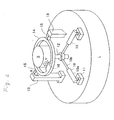
- Fig. 1 shows an embodiment of this invention wherein a machine is arranged for producing thrust or acceleration in the downward direction of gravity F of the earth.
- An outer cylindrical electrode 2 is mounted on a base 1 via an insulating ring 2a.
- a cylindrical rotor 3 is provided inside the electrode 2.
- the electrode 2 comprises an outer conductor layer 2A and an inner dielectric layer 2B.
- the rotor 3 comprises an inner conductor layer 3A and an outer dielectric layer 3B. There is a gap between the electrode 2 and the rotor 3 so that they do not touch.
- the rotor 3 is attached to an electrically conductive shaft 5 of a motor 4 through a conductive coupler 6.
- the motor 4 controls the revolution of the shaft 5 and the rotor 3, and a power supply 7 feeds power to the motor 4 through power lines 4a.
- a generator 8 is electrically connected to the power supply 7. In the event the motor 4 is an AC type and a DC generator 8 is provided, a DC-AC converter is included in the power supply 7.
- the generator 8 includes an electrical generator driven by, for example, a gas engine, solar power, man power, etc.
- the motor 4, the power supply 7, and the generator 8 are mounted on the base 1.
- An electric charge supply 9 is also mounted on the base 1 and receives energy from the power supply 7 or the generator 8.
- the electrodes 9a and 9b of the electric charge supply 9 are electrically connected to the electrode 2 and the rotor 3 respectively.
- the polarity of the electric charge supply 9 is preferably reversible.
- the generator 8 supplies power for the power supply 7 and the electric charge supply 9.
- the electric charge supply 9 provides a positive electric charge to the electrode 2, it provides a negative electric charge to the rotor 3 through the motor 4, the shaft 5, and the coupler 6, vice versa.
- the electrode 9b may be connected to the shaft 5 by conductive bearings or slip rings, for example.
- the amount of the generated vertical force or thrust depends on the magnitude of the charges and/or the rotational speed. Whether the generated vertical force or thrust is directed upwardly or downwardly depends on the polarity of the electric charge generator 9 but does not depend on the direction of rotation of the rotor 3.
- Fig. 2 shows another embodiment of this invention, wherein a machine comprises a larger-power machine L and a smaller-power machine S.
- the larger-power machine L and the smaller-power machine S are each functionally identical to the machine in Fig. 1, but differ only in the amount of power.
- the smaller-power machine S is connected to the larger-power machine L in such a manner that the axis of the smaller-power machine S can be oriented to any desired direction within a range of 45 degrees around the axis of the larger-power machine L, and can be fixed in that direction.
- the rotor is turned in a preset plane, its axis being perpendicular to the plane, and the electric charges established by the two electrodes are rotated in the plane, causing a force or thrust to be produced in the direction which is perpendicular to the preset plane and parallel with the axis of rotation of the charges and the rotor.
- Two cylinders 10 are universally jointed to bases 11 mounted on the larger power machine L.
- the rod 10b of each cylinder 10 is connected to the lower part of a central shaft 12 of the smaller power machine S.
- a pair of support pillars 13 stand on the larger machine L.
- a ring 14 is mounted rotatably in a direction shown by an arrow X on the upper part of the pillars 13 through pins 15.
- the smaller machine S is rotatably mounted in a direction as shown by an arrow Y inside the ring 14 through pins 16.
- the smaller-power machine S serves for attitude stabilization, selection of the accelerating direction and/or adjustment of the accelerating power.
- the larger-power machine L contributes mainly to the vertical thrust.
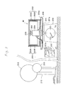
- Fig. 3 shows apparatus for conducting an experiment, which was carried out to show the vertical force generated by rotating electric charges in a horizontal plane. This experiment uses a machine described below, which is called a machine for experiment in order to distinguish it from the machine shown in Fig. 1.
- An outer electrode 202 is mounted on a base 201 via an insulating ring 202a.
- a rotor 203 is provided inside the electrode 202.
- the electrode 202 comprises an outer conductor layer 202A and an inner dielectric layer 202B, and the rotor 203 comprises an inner conductor layer 203A and an outer dielectric layer 203B. There is a gap between the electrode 202 and the rotor 203.
- the rotor 203 is connected to the conductive shaft 205 of a motor 204 through a conductive coupler 206.
- the motor 204 is fixed on the base 201 which has a cylindrical projection 201a.
- the motor controls the revolution of the conductor shaft 205 and the rotor, and constant-current power supply 207 feeds power to the motor 204.
- the base 201 is placed on a plate 208 of a weighing machine 209.
- An electric charge supply 210 such as a Van de Graaff generator, and a small spherical conductor 213 which does not have a charge generating function are not placed on the plate 208 of the weighing machine 209, but they are placed far from the electrode 202.
- the electric charge supply 210 has a spherical negative electrode 212.
- the minimum graduation of the weight indicator of the weighing machine 209 is 10 grams, and the distance between adjacent graduation lines is 1.5 mm.
- the weight of the machine for experiment was measured, and it turned out to be 1300 grams. This measurement was made several times while swinging the two wires connecting the motor 204 and the power supply 207, and no visible changes were detected. The total weight of the two wires is less than 1 gram. Therefore it can be said that the wires do not affect the results of the experiment.
- the power supply 207 was turned on, and fed a current of 3 A to the motor 204 in order to accelerate the rotor 203 rapidly.
- the result was that the reading of the weighing machine 209 fluctuated within a range of ⁇ 3 grams in the course of acceleration.
- the change in the weighing machine reading was checked at the top speed of the rotor 203 with the motor supplied with a current of 0.5 A.
- the difference between the reading at the top speed and that at rest was less than 1 gram. This difference can be considered to be caused by an interaction between the rotor rotation and the surrounding air.
- the charge supply 210 was turned on and was brought to a place near the machine for experiment so that the spherical electrode 212 touched the outer electrode 202. After one minute, the charge supply 210 was taken away to a place far from the machine, and was turned off.
- the positive terminal of the charge supply 210 was connected to the small spherical conductor 213, and the above measurements were repeated using this small spherical conductor 213, instead of the spherical negative electrode 212, as a source to charge the electrode 202.
- the reading of the weighing machine 209 was 1304 grams, indicating a weight increase of 4 grams. The same result was obtained when the rotor 203 was turned in the opposite direction.
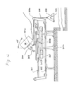
- Fig. 4 shows another system for an experiment, which was carried out to show a horizontal force generated by rotating electric charges around a tilted axis. This experiment uses the same machine M as that in experiment 1.
- Two parallel steel rod rails 301 are supported at both ends by a supporting frame 302 placed on a rigid table.
- a sliding mount 303 with a fixed needle 303a attached thereto is movably mounted on the rails 301 through four thrust-ball-bearings 303b. This sliding mount 303 can therefore roll freely along the straight rails 301.
- the cylindrical projection 201a of the machine for experiment is inserted with a tight fit in the cylindrical hole of a coupler 304, which is mounted on the sliding mount 303 at an angle of 45 degrees to the vertical.
- the sliding mount 303 is pulled toward the right by a cord 305, one end of which is connected to the sliding mount 303 and the other end of which is connected to a plate 306 loaded with a weight 308.
- a scale 307 of one-meter length is provided just behind the moving path of the needle 303a.
- the sliding mount 303 mounting the machine When the sliding mount 303 mounting the machine is brought to the left end of the rails 301 by hand and then is released, the sliding mount 303 is pulled by the weight 308 toward the right, and slides along the rails 301. As the sliding mount 303 moves, the reading of the scale 307, indicated by the needle 303a, changes. This process is repeated with various conditions and the time interval between the time when the reading of the scale 307 is 10 cm and that when the reading is 60 cm is measured.
- the time interval was measured with the rotor 203 of the machine M at rest and not charged. The time of movement between 10 cm. and 60 cm. was 3.8 seconds. Second, the time interval was measured with the rotor 203 in rotation and not charged. At the top speed of rotation, the measured time interval was again 3.8 seconds.
- the time interval was measured with the rotor 203 rotating and charged. As the rotational speed of the rotor 203 increased, the measured time interval decreased. At the top speed of rotation, the time interval between 10 cm. and 60 cm. was 3.4 seconds.
- the machine of this invention can generate not only a vertical force but also a horizontal force simply by tilting the rotational axis of the rotor.
- the machine generates a vertical or a horizontal acceleration or thrust, or in any desired direction.
- the machine is also useful for attitude stabilization of a craft.
- the machine generates acceleration in a direction by accelerating a polarized body in another direction, particularly one where the polarized body is a rotor that is rotatable in a gravitational field.
- the rotor may be oriented in a non-vertical direction, the rotor axis being variable and the rotor being electrically charged or magnetized.
- the rotational speed of the rotor is variable and/or reversible, and the degree of polarization is variable and/or reversible.
- the number of rotors may be two or more, and has at least one rotor whose axial direction is variable.
Landscapes
- Engineering & Computer Science (AREA)
- Chemical & Material Sciences (AREA)
- Combustion & Propulsion (AREA)
- Mechanical Engineering (AREA)
- General Engineering & Computer Science (AREA)
- Connection Of Motors, Electrical Generators, Mechanical Devices, And The Like (AREA)
Applications Claiming Priority (1)
| Application Number | Priority Date | Filing Date | Title |
|---|---|---|---|
| JP31213490 | 1990-11-16 |
Publications (2)
| Publication Number | Publication Date |
|---|---|
| EP0486243A2 true EP0486243A2 (fr) | 1992-05-20 |
| EP0486243A3 EP0486243A3 (fr) | 1994-03-16 |
Family
ID=18025665
Family Applications (1)
| Application Number | Title | Priority Date | Filing Date |
|---|---|---|---|
| EP91310395A Withdrawn EP0486243A2 (fr) | 1990-11-16 | 1991-11-11 | Dispositif d'accélération dans un champ de gravitation |
Country Status (1)
| Country | Link |
|---|---|
| EP (1) | EP0486243A2 (fr) |
Cited By (4)
| Publication number | Priority date | Publication date | Assignee | Title |
|---|---|---|---|---|
| RU2185526C1 (ru) * | 2001-05-21 | 2002-07-20 | Леонов Владимир Семенович | Способ создания тяги в вакууме и полевой двигатель для космического корабля (варианты) |
| RU2200875C2 (ru) * | 2000-05-17 | 2003-03-20 | Богданов Игорь Глебович | Электромагнитный двигатель богданова для создания тяги на новых физических принципах |
| US9337752B2 (en) | 2012-07-06 | 2016-05-10 | Richard Banduric | Interacting complex electric fields and static electric fields to effect motion |
| US10320312B2 (en) | 2012-07-06 | 2019-06-11 | Richard Banduric | Complex electric fields and static electric fields to effect motion with conduction currents and magnetic materials |
Families Citing this family (1)
| Publication number | Priority date | Publication date | Assignee | Title |
|---|---|---|---|---|
| RU2252335C2 (ru) * | 2003-04-29 | 2005-05-20 | Саратовский государственный технический университет | Способ получения из гравитационного поля экологически чистой энергии |
Family Cites Families (4)
| Publication number | Priority date | Publication date | Assignee | Title |
|---|---|---|---|---|
| FR2619861A1 (fr) * | 1971-04-08 | 1989-03-03 | Paraire Camille | Procede et dispositifs destines a provoquer le deplacement et eventuellement la sustentation d'un vehicule |
| US4663932A (en) * | 1982-07-26 | 1987-05-12 | Cox James E | Dipolar force field propulsion system |
| DE3608499A1 (de) * | 1986-03-14 | 1987-09-24 | Michael Schmid | Elektrischer energiewandler |
| AU5967190A (en) * | 1989-06-14 | 1991-01-08 | Randell L. Mills | Apparatus and method for providing an antigravitational force |
-
1991
- 1991-11-11 EP EP91310395A patent/EP0486243A2/fr not_active Withdrawn
Cited By (7)
| Publication number | Priority date | Publication date | Assignee | Title |
|---|---|---|---|---|
| RU2200875C2 (ru) * | 2000-05-17 | 2003-03-20 | Богданов Игорь Глебович | Электромагнитный двигатель богданова для создания тяги на новых физических принципах |
| RU2185526C1 (ru) * | 2001-05-21 | 2002-07-20 | Леонов Владимир Семенович | Способ создания тяги в вакууме и полевой двигатель для космического корабля (варианты) |
| WO2002095225A1 (fr) * | 2001-05-21 | 2002-11-28 | Pilkin, Vitaly Evgenievich | Procede de propulsion dans le vide et moteur a champ pour vehicule spatial (variantes) |
| US9337752B2 (en) | 2012-07-06 | 2016-05-10 | Richard Banduric | Interacting complex electric fields and static electric fields to effect motion |
| US10027257B2 (en) | 2012-07-06 | 2018-07-17 | Richard Banduric | Interacting complex electric fields and static electric fields to effect motion |
| US10320312B2 (en) | 2012-07-06 | 2019-06-11 | Richard Banduric | Complex electric fields and static electric fields to effect motion with conduction currents and magnetic materials |
| US10855210B2 (en) | 2012-07-06 | 2020-12-01 | Richard Banduric | Complex electric fields and static electric fields to effect motion with conduction currents and magnetic materials |
Also Published As
| Publication number | Publication date |
|---|---|
| EP0486243A3 (fr) | 1994-03-16 |
Similar Documents
| Publication | Publication Date | Title |
|---|---|---|
| WO2011031596A1 (fr) | Éliminateur d'électricité statique | |
| EP0486243A2 (fr) | Dispositif d'accélération dans un champ de gravitation | |
| KR20140078251A (ko) | 충전유닛을 갖는 쿼드로터 타입 비행체 | |
| JPS5829379A (ja) | 静電発電機 | |
| EP0758158A3 (fr) | Instrument de mesure à capacité électrostatique pour spires de stator de machines rotatives | |
| Kiziroglou et al. | Flexible substrate electrostatic energy harvester | |
| KR102453680B1 (ko) | 다축 진동 에너지 수확장치 | |
| US5473957A (en) | System for generating controllable reference environment and steerable translational force from interaction therewith | |
| JPH05118271A (ja) | 重力場での物体の加速方法及び加速機械 | |
| US2958790A (en) | Electrical thrust producing device | |
| CN106253738B (zh) | 一种高密度电荷电场发电机 | |
| Ieta et al. | First thrust measurements in ionic multi-propeller rotational engines | |
| CN110736903B (zh) | 一种电晕放电研究装置 | |
| JP3311988B2 (ja) | 静電高圧発生装置 | |
| CN212745763U (zh) | 摄像机稳定装置 | |
| JP2832216B2 (ja) | 静電気力を利用した動力発生装置 | |
| JPS6023514Y2 (ja) | 推力発生装置 | |
| JP2022069402A (ja) | 静電モータ | |
| CN107822792B (zh) | 一种用于轮椅车的随动型材和随动支架以及随动机构 | |
| CN206120962U (zh) | 人体电子元平衡仪便携机 | |
| JP2005039949A (ja) | リング状発電システム | |
| CN119400049A (zh) | 一种阻碍震荡电荷的旋转线圈实现干扰重力场的实验系统 | |
| CN213398754U (zh) | 一种静电测试装置 | |
| US634467A (en) | Electrical influence-machine. | |
| JPH11225404A (ja) | 車載用フライホイール・バッテリ |
Legal Events
| Date | Code | Title | Description |
|---|---|---|---|
| PUAI | Public reference made under article 153(3) epc to a published international application that has entered the european phase |
Free format text: ORIGINAL CODE: 0009012 |
|
| AK | Designated contracting states |
Kind code of ref document: A2 Designated state(s): DE FR GB |
|
| PUAL | Search report despatched |
Free format text: ORIGINAL CODE: 0009013 |
|
| AK | Designated contracting states |
Kind code of ref document: A3 Designated state(s): DE FR GB |
|
| STAA | Information on the status of an ep patent application or granted ep patent |
Free format text: STATUS: THE APPLICATION IS DEEMED TO BE WITHDRAWN |
|
| 18D | Application deemed to be withdrawn |
Effective date: 19931201 |