EP0485792A2 - Process for flame cutting under a liquid - Google Patents
Process for flame cutting under a liquid Download PDFInfo
- Publication number
- EP0485792A2 EP0485792A2 EP91118311A EP91118311A EP0485792A2 EP 0485792 A2 EP0485792 A2 EP 0485792A2 EP 91118311 A EP91118311 A EP 91118311A EP 91118311 A EP91118311 A EP 91118311A EP 0485792 A2 EP0485792 A2 EP 0485792A2
- Authority
- EP
- European Patent Office
- Prior art keywords
- oxygen
- heating
- fuel gas
- cutting
- nozzle
- Prior art date
- Legal status (The legal status is an assumption and is not a legal conclusion. Google has not performed a legal analysis and makes no representation as to the accuracy of the status listed.)
- Withdrawn
Links
Images

Classifications
-
- B—PERFORMING OPERATIONS; TRANSPORTING
- B23—MACHINE TOOLS; METAL-WORKING NOT OTHERWISE PROVIDED FOR
- B23K—SOLDERING OR UNSOLDERING; WELDING; CLADDING OR PLATING BY SOLDERING OR WELDING; CUTTING BY APPLYING HEAT LOCALLY, e.g. FLAME CUTTING; WORKING BY LASER BEAM
- B23K7/00—Cutting, scarfing, or desurfacing by applying flames
- B23K7/08—Cutting, scarfing, or desurfacing by applying flames by applying additional compounds or means favouring the cutting, scarfing, or desurfacing procedure
Definitions
- the invention relates to a method for flame cutting under a liquid according to the preamble of claim 1 and a device for carrying out the method according to the preamble of claim 9.
- the workpiece surface When flame cutting in the atmosphere, the workpiece surface is heated with a fuel gas-oxygen flame of a gas burner to at least the ignition temperature of the material, then cutting oxygen oxidizes part of the kerf material and the very strongly exothermic combustion reaction provides the heat for melting the neighboring material.
- the melt which consists of oxides and non-oxidized metal, is blown out of the kerf by the residual jet of the cutting oxygen.
- the crucial part of the gas burner is the flame cutting nozzle; it forms the cutting oxygen jet, the actual tool for flame cutting.
- Outlet openings for the heating flames are arranged rotationally symmetrically around the cutting oxygen jet in order to be able to cut in all horizontal directions when the cutting oxygen jet is blowing vertically downwards.
- the faster burning fuel gas acetylene is an advantage in most applications.
- the greatest possible cutting speeds depend on the properties of the cutting oxygen jet and on the thickness of the workpieces and on the material. The quality of the cut surface also limits the cutting speed.
- the heating flame is set with valves.
- fuel gas and oxygen are mixed in a ratio of 1 (fuel gas) to 1.1 to 1.3 (heating oxygen).
- the combustion of this gas mixture is incomplete.
- the resulting gases, carbon oxide and hydrogen, form an oxygen-free (reducing) zone in the flame.
- the oxygen required for the complete combustion of the fuel gas / heating oxygen mixture is taken from the surrounding air by the flame jacket.
- the invention has for its object to provide a method by means of which gas burners are used for thermal separation under water can be. This object is achieved by the characterizing features of claim 1.
- the invention has surprisingly shown that with an oxyacetylene burner under a liquid, preferably water, flame cuts with a cutting quality of the cutting surface in accordance with DIN 2310, Part 3, quality class 1 can be produced at almost the same cutting speed.
- the quality of the cut surfaces cut under water is better because the continuous cooling of the material area immediately adjacent to the cutting point results in a balanced heat balance over the entire material thickness, which prevents melting of the kerf on the material surface as well as deflection of the cutting oxygen jet on the exit side of the kerfs. Almost parallel cutting surfaces with the lowest chasing are achieved.
- a training example is shown in the drawing and is described in more detail below.
- a device for thermal flame cutting is designated by 1 in FIG. 1.
- the gas burner 20, shown only schematically, has a cutting nozzle 2.
- the cutting oxygen channel 3, which is arranged centrally in the cutting nozzle 2, is surrounded in a rotationally symmetrical manner by heating gas channels 4 and is connected to an oxygen supply 24 via a cutting oxygen supply 5 with a valve 40, which can preferably be controlled electrically.
- a heating gas mixture is generated in the annular space 21 connected to the heating gas channels 4, which is connected on the input side via a heating oxygen supply 22 and a fuel gas supply 23 to an oxygen supply 24 and a fuel gas supply 25.
- injector gas burner in which the mixture of fuel gas and heating oxygen takes place in an injector of the burner, instead of the gas-mixing nozzle of the gas burner 20.
- injector gas burners are known and therefore do not need to be described in more detail.
- a separate ignition gas mixture supply 6 opens into the cutting oxygen supply 5 connected to the cutting oxygen channel 3 and is connected to a fuel gas and oxygen supply 24, 25 via an injector 34 and preferably electrically controllable valves 31, 33.
- An electrical igniter 8, which is connected to the cutting oxygen supply 5, is arranged inside the gas burner 20 opposite the outflow opening of the ignition gas mixture supply 6.
- the ignition device 8 consists essentially of an ignition electrode with an opposite ground pin, with which an ignition spark is generated.
- the cutting nozzle 2 is positively surrounded by a gas jet nozzle 9 at least in the area of the outflow openings 27, 28 of the heating gas channels 4 and the cutting oxygen channel 3.
- the gas jet nozzle 9 can protrude flush with the cutting nozzle or up to 5 mm. As a result, stabilization can be achieved with slowly burning fuel gases.
- An outlet opening 10 is provided in the gas jet nozzle 9 and is connected to an oxygen supply 12 via a blowing oxygen supply 11 and a valve 7.
- the axis 13 of the outflow opening 10 extends at an angle 14 between 10 ° and 45 °, but preferably at an angle of 25 °. That of the device 1 assigned water basin is designated in its entirety with 15, the water surface with 16. The structure and functioning of such water basins are known and therefore do not need to be explained in more detail.
- a workpiece 17 is arranged on a flame cutting table, not shown; the surface of the workpiece is designated 18.
- valves 7, 26, 29, 30, 31, 33, 40 are preferably designed as a proportional pressure valve.
- the facility works as follows: The data for the corresponding process steps of the flame cutting process are stored in the computer 32 (microprocessor) in a memory in which further data such as the type of material, workpiece thickness and the like are stored.
- the gas burner 20 with the gas jet nozzle 9 assigned to it is arranged in a parking position above the water surface 16.
- the valve 33 receives the "ignition oxygen on” signal. Ignition oxygen now flows via the ignition gas mixture supply 6 into the cutting oxygen channel 3 and exits from the outlet opening 28.
- the valve 29 receives the "heating oxygen on” signal from the computer 32 via the control lines shown in dashed lines.
- the valve 7 is opened so that oxygen preferably exits the outflow opening 10 in the form of a jet.
- the gas burner 20 is on the Move the burner height and side drives, not shown, from the park position to the heating position, immersing them in the water basin 15.
- the valve 33 and valve 31 are opened. Pilot fuel gas and pilot oxygen mix in the injector 34 and flow as a pilot fuel gas mixture into the area of the igniter 8 and out of the outflow opening 28; Heating fuel gas mixes in the annular space 21 with the heating oxygen and flows as a heating gas mixture from the outflow opening 27 of the heating gas channels.
- the proportion of fuel gas, preferably of the fuel gas acetylene, in the fuel gas / heating oxygen mixture produced, based on the proportion of heating oxygen, is greater (excess fuel gas).
- the proportion must be greater than 1.7 and less than 2.5 times the proportion of heating oxygen, the quality of the cut surfaces 37 at almost atmospheric cutting speeds being greater than 1.8 and less than 2.2, preferably 1 , 85, of the fuel gas, based on the proportion of heating oxygen, are most advantageous.
- the ignition device 8 receives the control command "Ignition" from the computer 32 with a time delay.
- the ignition gas mixture is ignited via the ignition spark or spark.
- the pilot flame emerges from the outflow opening 28 for the "cutting oxygen” and ignites the fuel gas / heating oxygen mixture with an increased fuel gas content.
- the ignition is switched off, the valve 31 for the pilot fuel gas is closed and the oxygen pressure emerging from the outflow opening 10 is reduced.
- the gas burner 20 now runs by means of its side and Height drives to a predetermined position, preferably above the workpiece surface 18 and preheats it for the piercing process until the ignition temperature of the material is reached.
- the pressure of the heating oxygen is increased until the ignition temperature of the material is reached.
- the pressure of the heating oxygen is reduced and the cutting oxygen is switched on.
- the ignition oxygen is automatically switched off when the cutting oxygen is switched on via a lock.
- the valve 23 is closed.
- the cutting torch is then moved via drives according to the predetermined coordinates and the workpiece is flame cut, a fuel gas / heating oxygen mixture with excess fuel gas escaping from the flame cutting nozzle, and then oxygen is mixed in outside the torch nozzle via the oxygen jet emerging from the outlet opening 10.
- the cutting oxygen is switched off and the ignition oxygen is put in by coupling.
- the heating fuel gas is switched off and the burner is moved over the water surface 16.
- the ignition oxygen, the heating oxygen and the oxygen emerging from the outflow opening 10, which prevent the liquid from entering the gas burner, are then switched off.
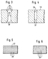
- a kerf and a cutting surface is shown as it forms after the flame cut in the atmosphere.
- the kerf according to FIG. 3 has a conical inlet 35 with edges 36 rounded to the workpiece surface 18, which continues in the central thickness region of the workpiece 17 with essentially parallel cutting surfaces 37.
- a conical widening 38 of the cut surfaces 37 takes place on the exit side of the cutting oxygen jet. This creates 37 comma-like grooves 39 on the cut surfaces, which curve in opposite directions or to the cutting direction.
- the kerf cut by flame according to the invention under a liquid according to FIG. 4 has almost parallel cutting surfaces 37 over the entire workpiece thickness, only the edges of the workpiece surface 18 and the workpiece lower surface being slightly rounded.
- FIG. 6 shows the course of the grooves 39 on the cutting surfaces 37 of carbon-containing steels flame-cut under a liquid. As can be seen from the illustration, the grooves 39 run almost straight.
Landscapes
- Engineering & Computer Science (AREA)
- Mechanical Engineering (AREA)
- Gas Burners (AREA)
Abstract
Description
Die Erfindung betrifft ein Verfahren zum Brennschneiden unter einer Flüssigkeit nach dem Oberbegriff des Anspruches 1 und eine Vorrichtung zur Durchführung des Verfahrens nach dem Oberbegriff des Anspruches 9.The invention relates to a method for flame cutting under a liquid according to the preamble of claim 1 and a device for carrying out the method according to the preamble of claim 9.
Beim Brennschneiden an der Atmosphäre wird die Werkstückoberfläche mit einer Brenngas-Sauerstoff-Flamme eines Gasbrenners auf mindestens Zündtemperatur des Werkstoffes erwärmt, dann oxidiert Schneidsauerstoff einen Teil des Schnittfugen-Werkstoffes und die sehr stark exotherme Verbrennungsreaktion liefert die Wärme zum Schmelzen des benachbarten Werkstoffes. Vom Reststrahl des Schneidsauerstoffes wird die Schmelze, die aus Oxiden und nicht oxidiertem Metall besteht, aus der Schnittfuge geblasen.When flame cutting in the atmosphere, the workpiece surface is heated with a fuel gas-oxygen flame of a gas burner to at least the ignition temperature of the material, then cutting oxygen oxidizes part of the kerf material and the very strongly exothermic combustion reaction provides the heat for melting the neighboring material. The melt, which consists of oxides and non-oxidized metal, is blown out of the kerf by the residual jet of the cutting oxygen.
Der entscheidende Teil des Gasbrenners ist die Brennschneiddüse; sie formt den Schneidsauerstoffstrahl, das eigentliche Werkzeug des Brennschneidens.The crucial part of the gas burner is the flame cutting nozzle; it forms the cutting oxygen jet, the actual tool for flame cutting.
Austrittsöffnungen für die Heizflammen sind rotationssymmetrisch um den Schneidsauerstoffstrahl angeordnet, um bei vertikal nach unten blasendem Schneidsauerstoffstrahl in allen horizontalen Richtungen schneiden zu können.Outlet openings for the heating flames are arranged rotationally symmetrically around the cutting oxygen jet in order to be able to cut in all horizontal directions when the cutting oxygen jet is blowing vertically downwards.
Für das Brennschneiden von Werkstückdicken bis 150 mm ist das schneller brennende Brenngas Acetylen in den meisten Anwendungsfällen von Vorteil. Die größtmöglichen Schneidgeschwindigkeiten hängen von den Eigenschaften des Schneidsauerstoffstrahles und von der Dicke der Werkstücke sowie von dem Werkstoff ab. Auch die Güte der Schnittfläche setzt der Schneidgeschwindigkeit Grenzen.For flame cutting of workpiece thicknesses up to 150 mm, the faster burning fuel gas acetylene is an advantage in most applications. The greatest possible cutting speeds depend on the properties of the cutting oxygen jet and on the thickness of the workpieces and on the material. The quality of the cut surface also limits the cutting speed.
Die Heizflamme wird mit Ventilen eingestellt. Bei der normalen Einstellung der Heizflamme werden Brenngas und Sauerstoff im Verhältnis 1 (Brenngas) zu 1,1 bis 1,3 (Heizsauerstoff) gemischt. Die Verbrennung dieses Gasgemisches ist unvollständig. Die dabei entstehenden Gase Kohlenoxid und Wasserstoff bilden in der Flamme eine sauerstofffreie (reduzierende) Zone. Der für die vollständige Verbrennung des Brenngas-Heizsauerstoff-Gemisches erforderliche Sauerstoff wird vom Flammenmantel aus der umgebenden Luft entnommen.The heating flame is set with valves. In the normal setting of the heating flame, fuel gas and oxygen are mixed in a ratio of 1 (fuel gas) to 1.1 to 1.3 (heating oxygen). The combustion of this gas mixture is incomplete. The resulting gases, carbon oxide and hydrogen, form an oxygen-free (reducing) zone in the flame. The oxygen required for the complete combustion of the fuel gas / heating oxygen mixture is taken from the surrounding air by the flame jacket.
Ausgehend von diesem Stand der Technik beim Brennschneiden an der Atmosphäre, liegt der Erfindung die Aufgabe zugrunde, ein Verfahren anzugeben, mittels dem Gasbrenner zum thermischen Trennen unter Wasser eingesetzt werden können.
Diese Aufgabe wird erfindungsgemäß durch die kennzeichnenden Merkmale des Anspruches 1 gelöst.Based on this prior art in flame cutting in the atmosphere, the invention has for its object to provide a method by means of which gas burners are used for thermal separation under water can be.
This object is achieved by the characterizing features of claim 1.
Durch die Erfindung hat sich überraschender Weise gezeigt, daß mit einem Autogenbrenner unter einer Flüssigkeit, vorzugsweise Wasser, Brennschnitte mit einer Schnittqualität der Schnittfläche gemäß DIN 2310, Teil 3, Güteklasse 1 bei nahezu gleicher Schneidgeschwindigkeit erzeugt werden können. Hierbei ist die Qualität der unter Wasser geschnittenen Schnittflächen besser, weil sich durch die kontinuierliche Kühlung des unmittelbar an die Schneidstelle angrenzenden Werkstoffbereiches eine ausgeglichene Wärmebilanz über die gesamte Werkstoffdicke einstellt, wodurch ein Aufschmelzen der Schnittfuge an der Werkstoffoberfläche ebenso verhindert wird, wie ein Ablenken des Schneidsauerstoffstrahles an der Austrittsseite der Schnittfugen. Es werden nahezu parallele Schnittflächen mit geringstem Riefennachlauf erreicht.The invention has surprisingly shown that with an oxyacetylene burner under a liquid, preferably water, flame cuts with a cutting quality of the cutting surface in accordance with DIN 2310,
Hinzu kommt, daß sich ein poröser, leicht abzulösender Schneidbart bildet. Der Lärmpegel wird bei entsprechender Wassertiefe wensentlich gesenkt. Stäube und Rauche werden im Wasser gebunden.In addition, a porous, easily removable cutting bit is formed. The noise level is significantly reduced when the water depth is sufficient. Dust and smoke are bound in the water.
Ein Ausbildungsbeispiel ist in der Zeichnung dargestellt und wird im folgenden näher beschrieben.A training example is shown in the drawing and is described in more detail below.
Es zeigen
- Fig. 1
- eine thermische Schneideinrichtung mit einem Gasbrenner nach der Erfindung in schematischer Darstellung.
- Fig. 2
- eine Draufsicht auf die Ausströmseite des Gasbrenners mit zugeordneter Gasstrahldüse.
- Fig. 3
- eine Ansicht der Schnittfuge wie sie sich beim Brennschnitt an der Atmosphäre ausbildet.
- Fig. 4
- eine Ansicht der Schnittfuge wie sie sich beim Brennschnitt nach der Erfindung ausbildet.
- Fig. 5
- eine Ansicht der Schnittfläche wie sie sich beim Brennschnitt an der Atmosphäre ausbildet.
- Fig. 6
- eine Ansicht der Schnittfläche wie sie sich beim Brennschnitt nach der Erfindung ausbildet.
- Fig. 1
- a thermal cutting device with a gas burner according to the invention in a schematic representation.
- Fig. 2
- a plan view of the outflow side of the gas burner with an associated gas jet nozzle.
- Fig. 3
- a view of the kerf as it is formed during the flame cut in the atmosphere.
- Fig. 4
- a view of the kerf as it is formed in the flame cut according to the invention.
- Fig. 5
- a view of the cut surface as it is formed in the atmosphere during the flame cut.
- Fig. 6
- a view of the cut surface as it is formed in the flame cut according to the invention.
In der Fig. 1 ist eine Vorrichtung zum thermischen Brennschneiden mit 1 bezeichnet. Der nur schematisch dargestellte Gasbrenner 20 weist eine Schneiddüse 2 auf. Der zentrisch in der Schneiddüse 2 angeordnete Schneidsauerstoffkanal 3 ist rotationssymmetrisch von Heizgaskanälen 4 umgeben und über eine Schneidsauerstoffzuführung 5 mit einem vorzugsweise elektrisch ansteuerbaren Ventil 40 mit einer Sauerstoffversorgung 24 verbunden. In dem mit den Heizgaskanälen 4 verbundenen Ringraum 21, der eingangsseitig über eine Heizsauerstoffzuführung 22 und eine Brenngaszuführung 23 an eine Sauerstoffversorgung 24 und eine Brenngasversorgung 25 angeschlossen ist, wird ein Heizgasgemisch erzeugt.A device for thermal flame cutting is designated by 1 in FIG. 1. The
Es ist selbstverständlich auch möglich, anstelle der gasemischenden Düse des Gasbrenners 20 einen Injektor-Gasbrenner, bei dem die Mischung von Brenngas und Heizsauerstoff in einem Injektor des Brenners stattfindet, einzusetzten. Derartige Injektor-Gasbrenner sind bekannt und brauchen daher nicht näher beschrieben zu werden.It is of course also possible to use an injector gas burner, in which the mixture of fuel gas and heating oxygen takes place in an injector of the burner, instead of the gas-mixing nozzle of the
In bevorzugter Ausbildung des Gasbrenners 20 mündet in die mit dem Schneidsauerstoffkanal 3 verbundene Schneidsauerstoffzuführung 5 eine separate Zündgasgemischzuführung 6, die über einen Injektor 34 und vorzugsweise elektrisch ansteuerbare Ventile 31, 33 mit einer Brenngas- und Sauerstoffversorgung 24 , 25 verbunden ist. Der Ausströmöffnung der Zündgasgemischzuführung 6 gegenüberliegend ist ein mit der Scneidsauerstoffzuführung 5 in Verbindung stehendes elektrisches Zündgerät 8 innerhalb des Gasbrenners 20 angeordnet. Das Zündgerät 8 besteht im wesentlichen aus einer Zündelektrode mit gegenüberliegendem Massestift, mit denen ein Zündfunke erzeugt wird.In a preferred embodiment of the
Die Schneiddüse 2 ist von einer Gasstrahldüse 9 wenigstens im Bereich der Ausströmöffnungen 27, 28 der Heizgaskanäle 4 und des Schneidsauerstoffkanales 3 formschlüssig umgeben. Dabei kann die Gasstrahldüse 9 mit der Schneiddüse bündig oder bis zu 5 mm überstehen. Hierdurch kann vorteilhaft eine Stabilisierung bei langsam verbrennenden Brenngasen erreicht werden. In der Gasstrahldüse 9 ist eine Austrittsöffnung 10 vorgesehen, die über eine Blassauerstoffzuführung 11 und ein Ventil 7 mit einer Sauerstoffversorgung 12 verbunden ist. Die Achse 13 der Ausströmöffnung 10 verläuft unter einem Winkel 14 zwischen 10° und 45°, vorzugsweise jedoch unter einem Winkel von 25°. Das der Vorrichtung 1 zugeordnete Wasserbecken ist in seiner Gesamtheit mit 15, die Wasseroberfläche mit 16 bezeichnet. Aufbau und Funktionsweise derartiger Wasserbecken sind bekannt und brauchen daher nicht näher erläutert zu werden.The cutting nozzle 2 is positively surrounded by a gas jet nozzle 9 at least in the area of the
In dem Wasserbecken ist ein Werkstück 17 auf einem nicht näher dargestellten Brennschneidtisch angeordnet; die Oberfläche des Werkstückes ist mit 18 bezeichnet ist.In the water basin, a
Die vorstehend beschriebenen Ventile 7, 26, 29, 30, 31, 33, 40) sind bevorzugt als Proportional-Druckventil ausgebildet.The
Die Einrichtung arbeitet wie folgt:
In den Rechner 32 (Microprozessor) werden die Daten für die entsprechenden Verfahrensschritte des Brennschneidvorganges in einem Speicher abgelegt, in dem weitere Daten wie Werkstoffart, Werkstückdicke und dergleichen gespeichert sind. Der Gasbrenner 20 mit der ihm zugeordneten Gasstrahldüse 9 ist oberhalb der Wasseroberfläche 16 in einer Parkposition angeordnet. Nach der manuellen Startfreigabe erhält das Ventil 33 das Signal "Zündsauerstoff ein". Zündsauerstoff strömt nun über die Zündgasgemischzuführung 6 in den Schneidsauerstoffkanal 3 und tritt aus der Austrittsöffnung 28 aus. Gleichzeitig erhält das Ventil 29 über die gestrichelt gezeichneten Steuerleitungen von dem Rechner 32 das Signal "Heizsauerstoff ein". Dieser strömt dann über die Heizsauerstoffzuführung 22, den Ringraum 21 in die Heizgaskanäle 4 und aus den Ausströmöffnungen 27. Das Ventil 7 wird geöffnet, so daß Sauerstoff vorzugsweise in Form eines Strahles aus der Ausströmöffnung 10 austritt. Anschließend wird der Gasbrenner 20 über die nicht näher dargestellten Brennerhöhen- und Seitenantriebe von der Parkposition in die Anheizposition verfahren, wobei er in das Wasserbecken 15 eintaucht. Nach dem Eintauchen, aber vor Erreichen der "richtigen" Höhe über dem Werkstück, werden das Ventil 33 und Ventil 31 geöffnet. Zündbrenngas und Zündsauerstoff vermischen sich in dem Injektor 34 und strömen als Zündbrenngasgemisch in den Bereich des Zündgerätes 8 und aus der Ausströmöffnung 28; Heizbrenngas mischt sich in dem Ringraum 21 mit dem Heizsauerstoff und strömt als Heizgasgemsich aus der Ausströmöffnung 27 der Heizgaskanäle. Dabei ist der Brenngasanteil, vorzugsweise des Brenngases Acetylen, an dem erzeugten Brenngas-Heizsauerstoff-Gemisch, bezogen auf den Anteil des Heizsauerstoffes, größer (Brenngasüberschuß). Versuche haben gezeigt, daß der Anteil größer 1,7 und kleiner 2,5 mal dem Anteil des Heizsauerstoffes sein muß, wobei die Qualität der Schnittflächen 37 bei nahezu Atmosphären-Schneidgeschwindigkeiten bei einem Anteil größer 1,8 und kleiner 2,2, vorzugsweise 1,85, des Brenngases, bezogen auf den Anteil des Heizsauerstoffes am Vorteilhaftesten sind. Beim Einschalten des Zündbrenngases und des Heizbrenngases wird der Druck des aus der Ausströmöffnung 10 strömenden Sauerstoffes erhöht. Zeitverzögert erhält das Zündgerät 8 von dem Rchner 32 den Steuerbefehl "Zünden". Über den bzw. die Zündfunken wird das Zündgasgemisch gezündet. Die Zündflamme tritt aus der Ausströmöffnung 28 für den "Schneidsauerstoff" aus und zündet das Brenngas-Heizsauerstoff-Gemisch mit erhöhtem Brenngasanteil. Die Zündung wird abgeschaltet, das Ventil 31 für das Zündbrenngas geschlossen und der aus der Ausströmöffnung 10 austretende Sauerstoffdruck erniedrigt.The facility works as follows:
The data for the corresponding process steps of the flame cutting process are stored in the computer 32 (microprocessor) in a memory in which further data such as the type of material, workpiece thickness and the like are stored. The
Der Gasbrenner 20 fährt nun mittels seiner Seiten- und Höhenantriebe auf eine vorgegebene Position, vorzugsweise über der Werkstückoberfläche 18 und heizt diese für den Lochstechvorgang bis zum Erreichen der Zündtemperatur des Werkstoffes vor. Hierzu wird der Druck des Heizsauerstoffes bis zum Erreichen der Zündtemperatur des Werkstoffes erhöht. Nach dem Durchstich durch das Werkstück wird der Druck des Heizsauerstoffes erniedrigt und der Schneidsauerstoff zugeschaltet. Über eine Verrieglung wird der Zündsauerstoff automatisch beim Einschalten des Scneidsauerstoffes ausgeschaltet. Das Ventil 23 wird geschlossen. Über Antriebe wird der Schneidbrenner nun entsprechend den vorgegebenen Koordinaten verfahren und das Werkstück brenngeschnitten, wobei aus der Brennschneiddüse ein Brenngas-Heizsauerstoff-Gemisch mit Brenngasüberschuß austritt, dann außerhalb der Brennerdüse über den aus der Ausströmöffnung 10 austretenden Sauerstoffstrahl Sauerstoff zugemischt wird.The
Ist der Brennschnitt beendet, wird der Schneidsauerstoff ausgeschaltet und über eine Kopplung der Zündsauerstoff eingeschlatet. Das Heizbrenngas wird abgeschaltet und der Brenner über die Wasseroberfläche 16 verfahren. Anschließend wird der Zündsauerstoff, der Heizsauerstoff und der aus der Ausströmöffnung 10 austretende Sauerstoff, welche ein Eindringen der Flüssigkeit in den Gasbrenner verhindern, abgeschaltet.When the flame cut is finished, the cutting oxygen is switched off and the ignition oxygen is put in by coupling. The heating fuel gas is switched off and the burner is moved over the
In den Fig. 3 und 5 ist eine Schnittfuge und eine Schnittfläche dargestellt, wie sie sich nach dem Brennschnitt an Atmosphäre ausbildet. Die Schnittfuge gemäß Fig. 3 weist einen konischen Einlauf 35 mit zur Werkstückoberfläche 18 gerundeten Kanten 36 auf, der sich im mittleren Dickenbereich des Werkstückes 17 mit im wesentlichen parallelen Schnittflächen 37 fortsetzt. An der Austrittsseite des Schneidsauerstoffstrahles findet wieder eine konische Aufweitung 38 der Schnittflächen 37 statt. Dabei entstehen an den Schnittflächen 37 kommaähnliche Riefen 39, die sich entgegengesetzt oder zur Schneidrichtung krümmen.3 and 5, a kerf and a cutting surface is shown as it forms after the flame cut in the atmosphere. The kerf according to FIG. 3 has a conical inlet 35 with
Im Gegensatz hierzu weist die nach der Erfindung unter einer Flüssigkeit brenngeschnittene Schnittfuge gemäß Fig. 4 nahezu parallele Schnittflächen 37 über die gesamte Werkstückdicke auf, wobei lediglich die Kanten zur Werkstückoberfläche 18 und zur Werkstückunterfläche leicht gerundet sind.In contrast to this, the kerf cut by flame according to the invention under a liquid according to FIG. 4 has almost parallel cutting surfaces 37 over the entire workpiece thickness, only the edges of the
In Fig. 6 ist der Verlauf der Riefen 39 an den Schnittflächen 37 von unter einer Flüssigkeit brenngeschnittenen kohlenstoffhaltigen Stählen dargestellt. Wie aus der Darstellung ersichtlich, verlaufen die Riefen 39 nahezu geradlinig.6 shows the course of the
Claims (11)
gekennzeichnet durch
einen Brenngasüberschuß des ausströmenden Brenngas-Heizsauerstoff-Gemisches.Process for flame cutting under a liquid, preferably under water, with a flame cutting nozzle from which a fuel gas / heating oxygen mixture flows,
marked by
a fuel gas excess of the outflowing fuel gas / heating oxygen mixture.
gekennzeichnet durch
einen Anteil größer 1 des Brenngases bezogen auf den Anteil des Heizsauerstoffes.Method according to claim 1,
marked by
a proportion greater than 1 of the fuel gas based on the proportion of heating oxygen.
gekennzeichnet durch
einen Anteil größer 1,7 und kleiner 2,5 bezogen auf den Anteil des Heizsauerstoffes.Method according to claim 1 or 2,
marked by
a proportion greater than 1.7 and less than 2.5 based on the proportion of heating oxygen.
gekennzeichnet durch
einen Anteil größer 1,8 und kleiner 2,2, vorzugsweise 1,85, des Brenngases bezogen auf den Anteil des Heizsauerstoffes.Method according to one of claims 1 to 3,
marked by
a proportion greater than 1.8 and less than 2.2, preferably 1.85, of the fuel gas based on the proportion of the heating oxygen.
dadurch gekennzeichnet,
daß dem ausströmenden Brenngas-Heizsauerstoff-Gemisch außerhalb der Brennschneiddüse Sauerstoff zugemischt wird.Method according to one of claims 1 to 4,
characterized,
that oxygen is added to the outflowing fuel gas / heating oxygen mixture outside the flame cutting nozzle.
dadurch gekennzeichnet,
daß der Anteil des außerhalb der Brennschneiddüse zugemischten Sauerstoffes das 2 bis 4fache des aus der Brennschneiddüse strömenden Anteiles des Heizsauerstoffes beträgt.Method according to claim 5,
characterized,
that the proportion of the oxygen admixed outside the cutting nozzle is 2 to 4 times the proportion of the heating oxygen flowing out of the cutting nozzle.
dadurch gekennzeichnet,
daß die automatische Steuerung gemäß folgenden Verfahrensschritten erfolgt:
characterized,
that the automatic control takes place according to the following procedural steps:
gekennzeichnet durch
einen Brenngasanteil größer 1,5 und kleiner 2,4 bei einem Anteil des Heizsauerstoffes von 1.Gas for flame cutting under a liquid,
marked by
a proportion of fuel gas greater than 1.5 and less than 2.4 with a proportion of heating oxygen of 1.
dadurch gekennzeichnet,
daß die Brennschneiddüse eine Ausströmöffnung (28) die Schneidsauerstoff in Form eines Strahles liefert, eine Mehrzahl von Heizöffnungen (27), welche um die Ausströmöffnung angeordnet sind und Mittel aufweist, zum Versorgen der Heizöffnungen (27) mit einem Gemisch aus einem Brenngas und einem Heizsauerstoff, das einen Brenngasüberschuß aufweist.Flame cutting device under a liquid with a flame cutting nozzle,
characterized,
that the flame cutting nozzle provides an outflow opening (28) which provides cutting oxygen in the form of a jet, a plurality of heating openings (27) which are arranged around the outflow opening and have means for supplying the heating openings (27) with a mixture of a fuel gas and a heating oxygen , which has an excess of fuel gas.
dadurch gekennzeichnet,
daß die Düse von einer Gasstrahldüse (9) umgeben ist, die eine in den Bereich zwischen den Düsenöffnungen (27, 28) und der Werkstückoberfläche (18) gerichteten Austrittsöffnung für einen Gasstrahl, vorzugsweise Sauerstoffstrahl, aufweist.Device according to claim 9,
characterized,
that the nozzle is surrounded by a gas jet nozzle (9) which has an outlet opening for a gas jet, preferably an oxygen jet, directed into the area between the nozzle openings (27, 28) and the workpiece surface (18).
dadurch gekennzeichnet,
daß ihr eine Steuerung für die Drücke der Gase zugeordnet ist, die aus elektrisch steuerbaren Ventilen (7, 26, 29, 30, 31, 33, 40), vorzugsweise Poroptional-Druckventilen, und einem Rechner (32) besteht, in dem mindestens die Daten für die Drücke eingebbar sind und der in Abhängigkeit von den Daten Steuersignale zum Einstellen der Drücke an den Ventilen erzeugt.Device according to claim 9 or 10,
characterized,
that it is assigned a control for the pressures of the gases, which consists of electrically controllable valves (7, 26, 29, 30, 31, 33, 40), preferably portional pressure valves, and a computer (32) in which at least the Data for the pressures can be entered and, depending on the data, generates control signals for setting the pressures on the valves.
Applications Claiming Priority (2)
| Application Number | Priority Date | Filing Date | Title |
|---|---|---|---|
| DE19904036486 DE4036486A1 (en) | 1990-11-16 | 1990-11-16 | FLAME-CUTTING METHOD UNDER A LIQUID |
| DE4036486 | 1990-11-16 |
Publications (1)
| Publication Number | Publication Date |
|---|---|
| EP0485792A2 true EP0485792A2 (en) | 1992-05-20 |
Family
ID=6418354
Family Applications (1)
| Application Number | Title | Priority Date | Filing Date |
|---|---|---|---|
| EP91118311A Withdrawn EP0485792A2 (en) | 1990-11-16 | 1991-10-28 | Process for flame cutting under a liquid |
Country Status (2)
| Country | Link |
|---|---|
| EP (1) | EP0485792A2 (en) |
| DE (1) | DE4036486A1 (en) |
Cited By (1)
| Publication number | Priority date | Publication date | Assignee | Title |
|---|---|---|---|---|
| FR2766397A1 (en) * | 1997-07-22 | 1999-01-29 | Metallurg Marnaise Soc | Oxygen@-cutting hardened steel plates |
-
1990
- 1990-11-16 DE DE19904036486 patent/DE4036486A1/en not_active Withdrawn
-
1991
- 1991-10-28 EP EP91118311A patent/EP0485792A2/en not_active Withdrawn
Cited By (1)
| Publication number | Priority date | Publication date | Assignee | Title |
|---|---|---|---|---|
| FR2766397A1 (en) * | 1997-07-22 | 1999-01-29 | Metallurg Marnaise Soc | Oxygen@-cutting hardened steel plates |
Also Published As
| Publication number | Publication date |
|---|---|
| DE4036486A1 (en) | 1992-05-21 |
Similar Documents
| Publication | Publication Date | Title |
|---|---|---|
| EP0017807B1 (en) | A process for reducing the build up of slag during flame cutting of metals and apparatus for carrying out the process | |
| DE3321697C2 (en) | ||
| DE3718597A1 (en) | CUTTING TORCH | |
| DE549781C (en) | Process for flame cutting cast iron | |
| DE4016181A1 (en) | METHOD AND DEVICE FOR LASER JET FLAME CUTTING | |
| EP0485792A2 (en) | Process for flame cutting under a liquid | |
| DE7109493U (en) | Flame cutting and marking device | |
| DE2855499C2 (en) | Inflation lance | |
| DE3721685A1 (en) | BANDCASTING FLAME-CUTTING MACHINE IN CONTINUOUS CASTING PLANTS | |
| DE3912988A1 (en) | METHOD FOR BOTTOMING AREAS OF OBJECTS WITH A BURNER | |
| DE2948777A1 (en) | Autogenous flame cutting, esp. using oxy-acetylene - where air is added to heating flame to ensure adequate preheating of thick workpieces | |
| DE2720793A1 (en) | PROCESS AND DEVICE FOR PERFORMING THERMOCHEMICAL QUICK START | |
| DE557598C (en) | Method and device for operating smelting furnaces, in particular Siemens-Martin-OEfen | |
| DE3730150A1 (en) | METHOD AND DEVICE FOR LENGTH CUTTING STRIPS | |
| DE2600876A1 (en) | PROCEDURE FOR CARRYING OUT FLAME RAPID STARTS | |
| EP0134907B1 (en) | Device for the pulsating supply of a gaseous medium to a kiln or suchlike | |
| DE3921455C1 (en) | Flame cutting machine - has two or more torches with adjustment for height above workpiece and oxygen supply lines | |
| DE4033618A1 (en) | UNDERWATER CUTTING METHOD | |
| DE2112083C (en) | Flame cutting and marking apparatus and method of marking using the apparatus | |
| DE2553553C2 (en) | Device for flaming a workpiece | |
| DE3149477C2 (en) | ||
| DE2321853B2 (en) | Method and nozzle for treating molten metal with a fluid jet! | |
| DE1901923A1 (en) | Method and device for focal beam slitting | |
| DE1529194C (en) | Welding torch insert | |
| DE1451428B1 (en) | Liquid burners for metallurgical ovens |
Legal Events
| Date | Code | Title | Description |
|---|---|---|---|
| PUAI | Public reference made under article 153(3) epc to a published international application that has entered the european phase |
Free format text: ORIGINAL CODE: 0009012 |
|
| AK | Designated contracting states |
Kind code of ref document: A2 Designated state(s): BE DE ES FR GB IT NL SE |
|
| STAA | Information on the status of an ep patent application or granted ep patent |
Free format text: STATUS: THE APPLICATION HAS BEEN WITHDRAWN |
|
| 18W | Application withdrawn |
Withdrawal date: 19920625 |
|
| R18W | Application withdrawn (corrected) |
Effective date: 19920625 |