EP0485080B1 - Locking tube connection - Google Patents
Locking tube connection Download PDFInfo
- Publication number
- EP0485080B1 EP0485080B1 EP91309526A EP91309526A EP0485080B1 EP 0485080 B1 EP0485080 B1 EP 0485080B1 EP 91309526 A EP91309526 A EP 91309526A EP 91309526 A EP91309526 A EP 91309526A EP 0485080 B1 EP0485080 B1 EP 0485080B1
- Authority
- EP
- European Patent Office
- Prior art keywords
- collet
- sleeve
- male component
- component
- male
- Prior art date
- Legal status (The legal status is an assumption and is not a legal conclusion. Google has not performed a legal analysis and makes no representation as to the accuracy of the status listed.)
- Expired - Lifetime
Links
Images
Classifications
-
- E—FIXED CONSTRUCTIONS
- E21—EARTH OR ROCK DRILLING; MINING
- E21B—EARTH OR ROCK DRILLING; OBTAINING OIL, GAS, WATER, SOLUBLE OR MELTABLE MATERIALS OR A SLURRY OF MINERALS FROM WELLS
- E21B17/00—Drilling rods or pipes; Flexible drill strings; Kellies; Drill collars; Sucker rods; Cables; Casings; Tubings
- E21B17/02—Couplings; joints
- E21B17/04—Couplings; joints between rod or the like and bit or between rod and rod or the like
- E21B17/042—Threaded
- E21B17/043—Threaded with locking means
-
- F—MECHANICAL ENGINEERING; LIGHTING; HEATING; WEAPONS; BLASTING
- F16—ENGINEERING ELEMENTS AND UNITS; GENERAL MEASURES FOR PRODUCING AND MAINTAINING EFFECTIVE FUNCTIONING OF MACHINES OR INSTALLATIONS; THERMAL INSULATION IN GENERAL
- F16L—PIPES; JOINTS OR FITTINGS FOR PIPES; SUPPORTS FOR PIPES, CABLES OR PROTECTIVE TUBING; MEANS FOR THERMAL INSULATION IN GENERAL
- F16L15/00—Screw-threaded joints; Forms of screw-threads for such joints
- F16L15/08—Screw-threaded joints; Forms of screw-threads for such joints with supplementary elements
Definitions
- the present invention relates to a locking connector between male and female components of a coupling, and more particularly to a locking connector between components of a drill string.
- drill collars may be placed above the milling tool such that the momentum of the drill collars whilst rotating drive the mill.
- this tends to make the mill wear unevenly, and may cause it to skim a section of casing.
- the increased rigidity of the assembly above the mill prevents the assembly from conforming readily to any deviation in the path of the casing being milled, and makes the milling round a "build" section in the casing very difficult; the mill will try to track straight down the hole, and this will tend to push the mill out of the side wall of the casing being milled.
- the design of the ring required a knurled surface on the face mating with the connection shoulder.
- a series of cams or ramps were provided around the inner mating faces.
- the present invention is intended to provide a locking device capable of resisting the momentum of the drill collars as the milling head decelerates, and thus preventing unscrewing and loss of the drill collars.
- US-A-4,693,498 discloses a locking connector for connection between a male component and a female component of a coupling, said connector comprising a collet having on a first end protruding fingers which interlock with recesses in one of said components.
- the present invention is characterised in that the locking connection further comprises a sleeve and a lock nut, and substantially fits over said male component on an external thread provided on the male component; said sleeve being movable and being provided with an internal thread for cooperation with the external thread whereby the sleeve is adapted to grip positively the end part of the collet on the surface of the male component; said lock nut being tightenable against the sleeve to hold the sleeve in position; and the recesses being provided on the female component.
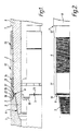
- FIG. 1 there is shown a locking connection between a female component 1 and a male component 2 of a coupling.
- the male component or shaft 2 has a tapering male screw threaded end 3 which cooperates with a compatible female screw threaded end 4 on the female receiving component 1, the female component having an annular end face 5.
- the threaded ends 3 and 4 of the male and female components may be screwed together such that the end face 5 of the female component abuts against a shoulder 6 on the male shaft and thus seals the connection against the engrees of internal fluid pressure.
- the threaded ends 3 and 4 are screwed together with a torque related to the size of the male and female components.
- Another shoulder 7 on the male shaft 1 forms a section of reduced diameter with respect to the remainder 8 of the male shaft, the section of reduced diameter lying between the threaded end 3 and the remainder of the shaft, and comprising a threaded length indicated by reference numeral 9 in Figure 2, a length indicated by reference numeral 10 having the same diameter as that of the thread on threaded length 9, and a length indicated by reference numeral 11 having a diameter slightly less than the diameter of threaded length 9.
- a sleeve 12 and a lock nut 13 are screwed on to the male shaft 2 before connection with the female component 1.
- the lock nut 13 may be screwed back to abut against shoulder 7, and the sleeve 12 may then be screwed back to abut against the lock nut 13 in this position.
- the sleeve 12 has an internally tapering diameter 14 at one end and the sleeve should be fitted on to the male part such that the taper 14 is at the end furthest away from lock nut 13.
- a collet 15 is fitted on to the length 11 which has for this purpose a slightly reduced diameter compared to the threaded length 9.
- a circumferential groove 16 is provided into which a snap ring 17 may be fitted as shown in Figure 1 to hold the collet in place on the male shaft.
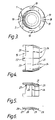
- a multiplicity of slots or recesses 18 is provided in the end of the female connection 1, as shown more clearly in Figure 3, a multiplicity of slots or recesses 18 is provided.
- Four recesses are shown in the illustrated embodiment, but this is only by way of example, and any number of recesses may be used the recesses 18 each have a precisely dimensioned width defined by sides 19.
- the collet 15 comprises a substantially cylindrical part 20 and a tapered end 21. Fingers 22 protrude from the end face 23 of the cylindrical part 20 and are adapted to cooperate with recesses 18 on the female component.
- the tapered end 21 has a multiplicity of slots 24.
- Figure 5 shows a partial axial cross section of the collet 15, and for clarity Figure 6 shows in cross section the annular wall of the collet only.
- the cylindrical inside diameter 25 of the tapered end 21 is serrated longitudinally.
- the inner face of part 20 has a section 26 with a diameter substantially the same as that of diameter 25.
- a shoulder 27 on the inner face of part 20′ forms a section 28 having a larger internal diameter than section 26.
- a recess 29 is formed between section 26 and the serrated diameter 25 .
- the slots 24 and the recess 29 allow the tapered end 21 to expand or to be bent inwards to some extent.
- the lock nut 13 is screwed on to the male shaft 2 until it abuts with shoulder 7.
- the sleeve 12 is fitted on to the male shaft and screwed back until it contacts the lock nut 13, taking care that the internally tapered end 14 of the sleeve is at the opposite end of the sleeve to that which contacts the lock nut.
- the collet 15 is then fitted over section 11 of the male shaft with tapered end 21 of the collet adapted to correspond to internal taper 14, such that the tapered end 21 slides under taper 14 on the sleeve 12.
- the snap ring 17 is fitted into groove 16 on the male shaft 2 behind the collet, and the collet is then allowed to move back such that the internal shoulder 27 of the collet bears against the snap ring 17; the collet then being restrained above the snap ring on the mile shaft.
- the collet fingers 22 are preferably held clear of the recesses whilst tightening the connection.
- the female connection 1 is then screwed on to the male shaft 2 by means of the complementary screw threads 3 and 4 until the appropriate torque is achieved and the end face 5 of the female connection abuts and seals against shoulder 6 on the male shaft.
- the fingers 22 on the collet are then allowed to engage with and slide into recesses 18 on the female connection.
- the recesses 18 are of sufficient depth that the fingers 22 do not foul the ends of the recesses.
- the widths of the recesses and of the fingers correspond very precisely.
- the sleeve 12 is then screwed down on to the collet such that the taper 14 on the sleeve fits over the tapered end 21 of the collet and the shoulder 27 bears against the snap ring 17.
- the snap ring ensures that the end face 23 of the collet remains clear of the end face 5 and the shoulder 6 which are torqued together, and thus reduces the effect of drag on the coupling.
- the serrated internal surface 25 bites into the surface 11 of the male shaft.
- lock nut 13 is screwed down and torqued against sleeve 12.
- the lock nut has a minimal clearance on the diameter of section 10 of the male shaft in order to reduce the ingress of surrounding fluids and contaminants.
- the breakout torque of the connection made up in the manner described above is thus increased, and is dependent on the size of the connections and the torques present on the assembly.
- the initial resistance to back-off is increased as the overall inertia in the locking connection has to be overcome.
Landscapes
- Engineering & Computer Science (AREA)
- Geology (AREA)
- Mechanical Engineering (AREA)
- General Engineering & Computer Science (AREA)
- Life Sciences & Earth Sciences (AREA)
- Mining & Mineral Resources (AREA)
- Fluid Mechanics (AREA)
- General Life Sciences & Earth Sciences (AREA)
- Geochemistry & Mineralogy (AREA)
- Physics & Mathematics (AREA)
- Environmental & Geological Engineering (AREA)
- Quick-Acting Or Multi-Walled Pipe Joints (AREA)
- Earth Drilling (AREA)
- Mechanical Coupling Of Light Guides (AREA)
- Joints That Cut Off Fluids, And Hose Joints (AREA)
- Dowels (AREA)
- Mutual Connection Of Rods And Tubes (AREA)
- Lock And Its Accessories (AREA)
- Enzymes And Modification Thereof (AREA)
- Preparation Of Compounds By Using Micro-Organisms (AREA)
Applications Claiming Priority (2)
| Application Number | Priority Date | Filing Date | Title |
|---|---|---|---|
| GB9022423A GB2248906B (en) | 1990-10-16 | 1990-10-16 | A locking connection |
| GB9022423 | 1990-10-16 |
Publications (2)
| Publication Number | Publication Date |
|---|---|
| EP0485080A1 EP0485080A1 (en) | 1992-05-13 |
| EP0485080B1 true EP0485080B1 (en) | 1994-06-08 |
Family
ID=10683785
Family Applications (1)
| Application Number | Title | Priority Date | Filing Date |
|---|---|---|---|
| EP91309526A Expired - Lifetime EP0485080B1 (en) | 1990-10-16 | 1991-10-16 | Locking tube connection |
Country Status (7)
| Country | Link |
|---|---|
| EP (1) | EP0485080B1 (da) |
| AT (1) | ATE106986T1 (da) |
| DE (1) | DE69102396T2 (da) |
| DK (1) | DK0485080T3 (da) |
| ES (1) | ES2057779T3 (da) |
| GB (1) | GB2248906B (da) |
| NO (1) | NO914066L (da) |
Families Citing this family (16)
| Publication number | Priority date | Publication date | Assignee | Title |
|---|---|---|---|---|
| GB9317128D0 (en) * | 1993-08-17 | 1993-09-29 | Swietlik George | Equipment to reduce torque on a drill string |
| BE1012618A3 (nl) | 1999-04-20 | 2001-01-09 | Bruyn Gaston Louis Jan De | Koppeling. |
| FR2848015B1 (fr) * | 2002-11-29 | 2005-03-25 | Framatome Anp | Dispositif de freinage en rotation de vis de fixation de deux tubes |
| GB0413042D0 (en) | 2004-06-11 | 2004-07-14 | Petrowell Ltd | Sealing system |
| GB0423992D0 (en) | 2004-10-29 | 2004-12-01 | Petrowell Ltd | Improved plug |
| GB0507237D0 (en) | 2005-04-09 | 2005-05-18 | Petrowell Ltd | Improved packer |
| GB2450648B (en) | 2006-03-23 | 2011-10-19 | Petrowell Ltd | Improved packer |
| GB0622916D0 (en) | 2006-11-17 | 2006-12-27 | Petrowell Ltd | Improved tree plug |
| JP5527641B2 (ja) * | 2007-05-21 | 2014-06-18 | Smc株式会社 | 流体圧機器の接続具 |
| GB0711871D0 (en) | 2007-06-20 | 2007-07-25 | Petrowell Ltd | Improved activation device |
| GB0723607D0 (en) | 2007-12-03 | 2008-01-09 | Petrowell Ltd | Improved centraliser |
| GB0803123D0 (en) | 2008-02-21 | 2008-03-26 | Petrowell Ltd | Improved tubing section |
| GB0804961D0 (en) | 2008-03-18 | 2008-04-16 | Petrowell Ltd | Improved centraliser |
| GB0805719D0 (en) * | 2008-03-29 | 2008-04-30 | Petrowell Ltd | Improved tubing section coupling |
| WO2010142038A1 (en) * | 2009-06-12 | 2010-12-16 | Atlas Copco Thiessen | Drill rod locking assembly |
| CN102146772B (zh) * | 2011-02-15 | 2013-04-17 | 宝鸡石油机械有限责任公司 | 一种旋转型锁块式钻井隔水管连接器 |
Family Cites Families (6)
| Publication number | Priority date | Publication date | Assignee | Title |
|---|---|---|---|---|
| US3361453A (en) * | 1965-07-02 | 1968-01-02 | Brown Oil Tools | Quick coupling device |
| GB2066332A (en) * | 1979-12-29 | 1981-07-08 | Andred Associates Ltd | Drilling stabiliser |
| CA1148193A (en) * | 1980-01-11 | 1983-06-14 | Kornelis N. Zijlstra | Coupling for interconnecting pipe sections and pipe section for well drilling operations |
| US4693498A (en) * | 1986-04-28 | 1987-09-15 | Mobil Oil Corporation | Anti-rotation tubular connection for flowlines or the like |
| US4773477A (en) * | 1987-03-24 | 1988-09-27 | Norman A. Nelson | Well suspension assembly |
| US4903992A (en) * | 1989-04-14 | 1990-02-27 | Vetco Gray Inc. | Locking ring for oil well tool |
-
1990
- 1990-10-16 GB GB9022423A patent/GB2248906B/en not_active Expired - Fee Related
-
1991
- 1991-10-16 DE DE69102396T patent/DE69102396T2/de not_active Expired - Fee Related
- 1991-10-16 DK DK91309526.1T patent/DK0485080T3/da active
- 1991-10-16 EP EP91309526A patent/EP0485080B1/en not_active Expired - Lifetime
- 1991-10-16 AT AT91309526T patent/ATE106986T1/de active
- 1991-10-16 ES ES91309526T patent/ES2057779T3/es not_active Expired - Lifetime
- 1991-10-16 NO NO91914066A patent/NO914066L/no unknown
Also Published As
| Publication number | Publication date |
|---|---|
| GB2248906B (en) | 1994-04-27 |
| EP0485080A1 (en) | 1992-05-13 |
| GB9022423D0 (en) | 1990-11-28 |
| NO914066L (no) | 1992-04-21 |
| DE69102396D1 (de) | 1994-07-14 |
| NO914066D0 (no) | 1991-10-16 |
| DE69102396T2 (de) | 1994-12-01 |
| ES2057779T3 (es) | 1994-10-16 |
| DK0485080T3 (da) | 1994-09-26 |
| ATE106986T1 (de) | 1994-06-15 |
| GB2248906A (en) | 1992-04-22 |
Similar Documents
| Publication | Publication Date | Title |
|---|---|---|
| EP0485080B1 (en) | Locking tube connection | |
| US4630690A (en) | Spiralling tapered slip-on drill string stabilizer | |
| US4600063A (en) | Double-taper slip-on drill string stabilizer | |
| EP0254552B1 (en) | Improvements in or relating to joints for tubular members | |
| US4245709A (en) | Removable drill string stabilizers | |
| US20030075924A1 (en) | Connection | |
| US12240047B2 (en) | Quick-release coupling for drilling and related methods | |
| US8950785B2 (en) | Broach style anti rotation device for connectors | |
| JPH0761616B2 (ja) | ボルト抜き取り装置 | |
| GB2132727A (en) | Pipe joint locking device | |
| US4902047A (en) | Thread connector anti-rotation device | |
| RU2760380C2 (ru) | Горная буровая система с переходником | |
| US2214241A (en) | Collet | |
| US4728124A (en) | Connection for drilling | |
| US4576402A (en) | Locking pipe sub | |
| US6868756B2 (en) | Device to extract broken fasteners embedded in a workpiece | |
| JPH06200690A (ja) | パイプをドリル・ストリングに鎖錠する鎖錠機構とパイプ固定方法 | |
| US4390064A (en) | Junk basket | |
| JPS6226392B2 (da) | ||
| DE1627384A1 (de) | Selbstauskuppelnder Werkzeughalter | |
| US12331476B2 (en) | System for coupling of piles | |
| EP0083860B1 (en) | A drive attachment for a power drill or like tool | |
| EP0124468A1 (en) | Pin and box connector assembly | |
| US12305452B2 (en) | Centralizer having internal stop collar | |
| CN118835926B (zh) | 一种可调弯接头 |
Legal Events
| Date | Code | Title | Description |
|---|---|---|---|
| PUAI | Public reference made under article 153(3) epc to a published international application that has entered the european phase |
Free format text: ORIGINAL CODE: 0009012 |
|
| AK | Designated contracting states |
Kind code of ref document: A1 Designated state(s): AT BE CH DE DK ES FR GB GR IT LI LU NL SE |
|
| 17P | Request for examination filed |
Effective date: 19920611 |
|
| 17Q | First examination report despatched |
Effective date: 19930427 |
|
| GRAA | (expected) grant |
Free format text: ORIGINAL CODE: 0009210 |
|
| AK | Designated contracting states |
Kind code of ref document: B1 Designated state(s): AT BE CH DE DK ES FR GR IT LI LU NL SE |
|
| REF | Corresponds to: |
Ref document number: 106986 Country of ref document: AT Date of ref document: 19940615 Kind code of ref document: T |
|
| REF | Corresponds to: |
Ref document number: 69102396 Country of ref document: DE Date of ref document: 19940714 |
|
| ITF | It: translation for a ep patent filed | ||
| REG | Reference to a national code |
Ref country code: DK Ref legal event code: T3 |
|
| ET | Fr: translation filed | ||
| REG | Reference to a national code |
Ref country code: ES Ref legal event code: FG2A Ref document number: 2057779 Country of ref document: ES Kind code of ref document: T3 |
|
| REG | Reference to a national code |
Ref country code: GR Ref legal event code: FG4A Free format text: 3013087 |
|
| EAL | Se: european patent in force in sweden |
Ref document number: 91309526.1 |
|
| PLBE | No opposition filed within time limit |
Free format text: ORIGINAL CODE: 0009261 |
|
| STAA | Information on the status of an ep patent application or granted ep patent |
Free format text: STATUS: NO OPPOSITION FILED WITHIN TIME LIMIT |
|
| 26N | No opposition filed | ||
| PGFP | Annual fee paid to national office [announced via postgrant information from national office to epo] |
Ref country code: LU Payment date: 19961001 Year of fee payment: 6 |
|
| PGFP | Annual fee paid to national office [announced via postgrant information from national office to epo] |
Ref country code: FR Payment date: 19961009 Year of fee payment: 6 Ref country code: DK Payment date: 19961009 Year of fee payment: 6 |
|
| PGFP | Annual fee paid to national office [announced via postgrant information from national office to epo] |
Ref country code: AT Payment date: 19961011 Year of fee payment: 6 |
|
| PGFP | Annual fee paid to national office [announced via postgrant information from national office to epo] |
Ref country code: SE Payment date: 19961016 Year of fee payment: 6 |
|
| PGFP | Annual fee paid to national office [announced via postgrant information from national office to epo] |
Ref country code: CH Payment date: 19961023 Year of fee payment: 6 |
|
| PGFP | Annual fee paid to national office [announced via postgrant information from national office to epo] |
Ref country code: DE Payment date: 19961025 Year of fee payment: 6 |
|
| PGFP | Annual fee paid to national office [announced via postgrant information from national office to epo] |
Ref country code: NL Payment date: 19961029 Year of fee payment: 6 |
|
| PGFP | Annual fee paid to national office [announced via postgrant information from national office to epo] |
Ref country code: ES Payment date: 19961030 Year of fee payment: 6 |
|
| PGFP | Annual fee paid to national office [announced via postgrant information from national office to epo] |
Ref country code: GR Payment date: 19961031 Year of fee payment: 6 |
|
| PGFP | Annual fee paid to national office [announced via postgrant information from national office to epo] |
Ref country code: BE Payment date: 19961128 Year of fee payment: 6 |
|
| PG25 | Lapsed in a contracting state [announced via postgrant information from national office to epo] |
Ref country code: LU Free format text: LAPSE BECAUSE OF NON-PAYMENT OF DUE FEES Effective date: 19971016 Ref country code: AT Free format text: LAPSE BECAUSE OF NON-PAYMENT OF DUE FEES Effective date: 19971016 |
|
| REG | Reference to a national code |
Ref country code: DK Ref legal event code: EBP |
|
| PG25 | Lapsed in a contracting state [announced via postgrant information from national office to epo] |
Ref country code: SE Free format text: LAPSE BECAUSE OF NON-PAYMENT OF DUE FEES Effective date: 19971017 Ref country code: ES Free format text: LAPSE BECAUSE OF EXPIRATION OF PROTECTION Effective date: 19971017 |
|
| PG25 | Lapsed in a contracting state [announced via postgrant information from national office to epo] |
Ref country code: LI Free format text: LAPSE BECAUSE OF NON-PAYMENT OF DUE FEES Effective date: 19971031 Ref country code: GR Free format text: LAPSE BECAUSE OF NON-PAYMENT OF DUE FEES Effective date: 19971031 Ref country code: FR Free format text: THE PATENT HAS BEEN ANNULLED BY A DECISION OF A NATIONAL AUTHORITY Effective date: 19971031 Ref country code: DK Free format text: LAPSE BECAUSE OF NON-PAYMENT OF DUE FEES Effective date: 19971031 Ref country code: CH Free format text: LAPSE BECAUSE OF NON-PAYMENT OF DUE FEES Effective date: 19971031 Ref country code: BE Free format text: LAPSE BECAUSE OF NON-PAYMENT OF DUE FEES Effective date: 19971031 |
|
| BERE | Be: lapsed |
Owner name: THE RED BARON (OIL TOOLS RENTAL) LTD Effective date: 19971031 |
|
| PG25 | Lapsed in a contracting state [announced via postgrant information from national office to epo] |
Ref country code: NL Free format text: LAPSE BECAUSE OF NON-PAYMENT OF DUE FEES Effective date: 19980501 |
|
| REG | Reference to a national code |
Ref country code: CH Ref legal event code: PL |
|
| NLV4 | Nl: lapsed or anulled due to non-payment of the annual fee |
Effective date: 19980501 |
|
| PG25 | Lapsed in a contracting state [announced via postgrant information from national office to epo] |
Ref country code: DE Free format text: LAPSE BECAUSE OF NON-PAYMENT OF DUE FEES Effective date: 19980701 |
|
| EUG | Se: european patent has lapsed |
Ref document number: 91309526.1 |
|
| REG | Reference to a national code |
Ref country code: FR Ref legal event code: ST |
|
| REG | Reference to a national code |
Ref country code: ES Ref legal event code: FD2A Effective date: 20010201 |
|
| PG25 | Lapsed in a contracting state [announced via postgrant information from national office to epo] |
Ref country code: IT Free format text: LAPSE BECAUSE OF NON-PAYMENT OF DUE FEES;WARNING: LAPSES OF ITALIAN PATENTS WITH EFFECTIVE DATE BEFORE 2007 MAY HAVE OCCURRED AT ANY TIME BEFORE 2007. THE CORRECT EFFECTIVE DATE MAY BE DIFFERENT FROM THE ONE RECORDED. Effective date: 20051016 |