EP0484883B1 - Fördersystem mit Antriebsflächen eines Förderbandmoduls, die im Scharnierbereich mit einem Antriebszahnrad zusammenwirken - Google Patents
Fördersystem mit Antriebsflächen eines Förderbandmoduls, die im Scharnierbereich mit einem Antriebszahnrad zusammenwirken Download PDFInfo
- Publication number
- EP0484883B1 EP0484883B1 EP91118842A EP91118842A EP0484883B1 EP 0484883 B1 EP0484883 B1 EP 0484883B1 EP 91118842 A EP91118842 A EP 91118842A EP 91118842 A EP91118842 A EP 91118842A EP 0484883 B1 EP0484883 B1 EP 0484883B1
- Authority
- EP
- European Patent Office
- Prior art keywords
- belt
- drive
- sprocket
- pivot rod
- modular
- Prior art date
- Legal status (The legal status is an assumption and is not a legal conclusion. Google has not performed a legal analysis and makes no representation as to the accuracy of the status listed.)
- Expired - Lifetime
Links
- 230000013011 mating Effects 0.000 title claims description 10
- 230000033001 locomotion Effects 0.000 claims description 12
- 230000014759 maintenance of location Effects 0.000 claims description 7
- 230000005489 elastic deformation Effects 0.000 claims 2
- 230000037361 pathway Effects 0.000 claims 1
- 230000000717 retained effect Effects 0.000 claims 1
- 230000008901 benefit Effects 0.000 description 4
- 238000005201 scrubbing Methods 0.000 description 4
- 230000003993 interaction Effects 0.000 description 2
- 230000002093 peripheral effect Effects 0.000 description 2
- 230000036544 posture Effects 0.000 description 2
- 230000009471 action Effects 0.000 description 1
- 230000005540 biological transmission Effects 0.000 description 1
- 230000001939 inductive effect Effects 0.000 description 1
- 230000007246 mechanism Effects 0.000 description 1
- 230000010355 oscillation Effects 0.000 description 1
Images


Classifications
-
- B—PERFORMING OPERATIONS; TRANSPORTING
- B65—CONVEYING; PACKING; STORING; HANDLING THIN OR FILAMENTARY MATERIAL
- B65G—TRANSPORT OR STORAGE DEVICES, e.g. CONVEYORS FOR LOADING OR TIPPING, SHOP CONVEYOR SYSTEMS OR PNEUMATIC TUBE CONVEYORS
- B65G17/00—Conveyors having an endless traction element, e.g. a chain, transmitting movement to a continuous or substantially-continuous load-carrying surface or to a series of individual load-carriers; Endless-chain conveyors in which the chains form the load-carrying surface
- B65G17/06—Conveyors having an endless traction element, e.g. a chain, transmitting movement to a continuous or substantially-continuous load-carrying surface or to a series of individual load-carriers; Endless-chain conveyors in which the chains form the load-carrying surface having a load-carrying surface formed by a series of interconnected, e.g. longitudinal, links, plates, or platforms
- B65G17/08—Conveyors having an endless traction element, e.g. a chain, transmitting movement to a continuous or substantially-continuous load-carrying surface or to a series of individual load-carriers; Endless-chain conveyors in which the chains form the load-carrying surface having a load-carrying surface formed by a series of interconnected, e.g. longitudinal, links, plates, or platforms the surface being formed by the traction element
-
- B—PERFORMING OPERATIONS; TRANSPORTING
- B65—CONVEYING; PACKING; STORING; HANDLING THIN OR FILAMENTARY MATERIAL
- B65G—TRANSPORT OR STORAGE DEVICES, e.g. CONVEYORS FOR LOADING OR TIPPING, SHOP CONVEYOR SYSTEMS OR PNEUMATIC TUBE CONVEYORS
- B65G2201/00—Indexing codes relating to handling devices, e.g. conveyors, characterised by the type of product or load being conveyed or handled
- B65G2201/02—Articles
-
- B—PERFORMING OPERATIONS; TRANSPORTING
- B65—CONVEYING; PACKING; STORING; HANDLING THIN OR FILAMENTARY MATERIAL
- B65G—TRANSPORT OR STORAGE DEVICES, e.g. CONVEYORS FOR LOADING OR TIPPING, SHOP CONVEYOR SYSTEMS OR PNEUMATIC TUBE CONVEYORS
- B65G2207/00—Indexing codes relating to constructional details, configuration and additional features of a handling device, e.g. Conveyors
- B65G2207/30—Modular constructions
Definitions
- This invention relates to the structural characteristics of conveyor belt modules, and more particularly to interacting module and sprocket drive surfaces coacting at the hinging joints.
- Modularized conveyor belts and accompanying drive systems are well known in the art, and are found with modules of various characteristics that are coupled together and articulated by means of pivot rods so that they can be endlessly moved by means of rotatable sprockets.
- the trend in the art is to produce modules of various shapes and interactions for achieving various advantages in operation.
- EP-A-0 380 201 discloses a module having a top and bottom surface suitable for being pivotally connected with a multiplicity of similar modules by pivot rods to construct a conveyor belt which can move along a predetermined path, said module comprising: a plurality of elongated links extending the length of the module, each of said plurality of elongated links defining a first set of pivot holes aligned along a first pivot axis in the link ends at one end and a second set of pivot holes aligned along a second pivot axis in the link ends at the other end of said elongated link and also including a portion thereof which is not orthogonal to said pivot axes; the link ends of each link of said module suitable for being intermeshed and pivotally connected by pivot rods extending through said pivot holes with the link ends of similar module to form a conveyor belt; an integrally molded connecting structure extending transverse to said elongated links so as to join and maintain the other and having a bottom-most point which terminates substantially at said bottom
- one objective of this invention is to provide improved simplified modular elements and conveyor belt drive systems embodying modular elements.
- a critical operational region in conveyor belt systems driven by a sprocket at the hinged joints is caused by the hinging driving interface between the belt modules and the relatively moving rotating sprocket drive surfaces.
- the prior art has many different configurations of sprocket and belt structure with special driving surface features.
- the prior art hinge region drive surfaces present operational disadvantages.
- some of the critical operating conditions involved are the wear at interfacing drive surfaces, the ability of the belt to articulate smoothly over small diameter sprockets, the performance of the belt over the range of no-load to full-load conditions, the energy or friction losses of the drive system, the ability to run at various speeds, freedom from vibration and noise, and the ease of replacing worn surfaces or parts.
- a still further objective of this invention is to provide an improved conveyor belt system wherein interacting belt-sprocket drive forces that tend to drive the belt away from the sprocket are avoided.
- a modularized conveyor belt is formed from variously shaped modular members, illustrated for example in a wishbone-shaped embodiment defining modular elements with three fingers or link ends.
- the modular elements may be coupled together in one or more multiple element units disposed across the width of a belt.
- a stem extends in one direction and two bifurcated fingers extend in the opposite direction.
- Spocket tooth drive surfaces are formed by the stem ends which surround journalled apertures for receiving pivot rods.
- the various modules for which this invention is directed have in common drive surfaces in the hinging region which move dynamically during articulation and thus produce an interface with mating sprocket drive surfaces.
- Modular members of one or more wishbone elements when connected side by side and end to end into a belt by pivot rods thus have disposed about pivot rods side-by-side interfacing drive members extending alternately in opposite directions about pivot rods toward respective end to end articulating modules.
- Different configurations permit links to be articulated at opposite ends about a pivot rod, or groups of such links held together in modular units of predetermined width across the belt by means of integral interconnecting structure such as connecting crossbeams, usually centrally positioned along the length of the modular elements and disposed normally to the direction of belt travel.
- the belt loading surface of one class of modular links or modular units terminates in a plane, which could be a suitably apertured flat sheet surface, for example, or alternatively an open gridwork arrangement.
- Another class of modular members may have non-planar belt loading surfaces.
- a typical drive surface afforded by this invention could comprise a generally trapezoidal drive tooth shape with planar sidewalls extending inwardly from the belt towards a drive sprocket and integrally formed on the generally cylindrical surfaces disposed about the pivot rod to form journalling apertures.
- Belt systems in general are driven by a rotary sprocket wheel with peripheral teeth entering mating apaertures defined in the belt assembly to interface with the interacting module drive surfaces surrounding the pivot rod.
- a drive force reacts on the pivot rod through generally cylindrical contact surfaces surrounding the pivot rods at opposite ends of the modular members.
- the entry angle of the sprocket drive tooth surfaces with respect to the module drive tooth surfaces requires the sprocket and module during the dynamic articulating motion to engage at two substantially parallel interacting drive surfaces accommodating entry of the module drive tooth into and exit from the sprocket wheel or drive contact without interference to impart tangential drive forces along the belt without tending to force the belt away from the sprocket wheel.
- two substantially planar surfaces are mated with substantially parallel dynamic movement for both entry and exit of sprocket driving teeth into and out of the belt configuration.
- the respective planar drive surfaces of the sprocket are disposed generally radially with respect to the sprocket wheel drive axis for mating in movement over a pre-determined sprocket arc.
- the module members form sprocket channels or notches for sprocket drive teeth to enter or leave the belt with the sprocket and module tooth surfaces disposed substantially parallel during articulation so that radial forces outwardly from the sprocket tending to drive the belt away from the sprocket are avoided.
- the link end pivot rod journalling surfaces at the drive interfaces forming a belt drive tooth may have a different radius center at leading and trailing tooth surfaces.
- the two walls formed about the pivot rod at the module link finger ends in a plane parallel to the belt to form the drive tooth have different thicknesses to produce a thinner inside edge surrounding cylindrical wall positioned inwardly in the driven link in the driving direction than the corresponding outside driven edge wall thickness directed away from the driven link ends. This avoids any interference, scrubbing or wear on the sprocket teeth from the adjacent interdigited link ends of the adjoining modular section during dynamic reaction with sprocket drive teeth at the articulation joint.
- the modular belt conveyor system drive interface between the module links and the sprocket interengage in movement onto, about and away from the rotating sprocket wheel to produce substantially only circumferentially oriented drive forces tangential to the belt.
- the substantially tangential drive forces avoids interference and radial oscillation or flapping of the belt to keep noise, friction, vibration and wear at a minimum and maintains the belt in good circumferential contact with the sprocket wheel under all conditions from no-load to full-load.
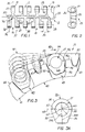
- the belt module embodiment 15 is formed of four wishbone shaped basic modular links 16, 17, 18, 19, held in place by a substantially longitudinal transverse rod support structure 20 or connecting beam integrally joining the modular members 16, 17, 18 & 19 to provide a multi-linked modular unit.
- the modular unit is molded from plastic and the connecting beam need not bear weight or act as a structural element such as drive member, but forms the individual links into a modular unit.
- the top of the belt 25 forming the working surface is generally flat or planar, and drive surfaces extend from the underside as teeth 26.
- Axial apertures 27 formed in the module fingers 30, 31, 32 receive and journal pivot rods in fixed alignment along two parallel pivot rod receiving axes (28).
- the belt edge wishbone link 19 of the module 15 forms a retaining cap 29 for preventing axial movement of the pivot rods out of the belt toward the right.
- the cap 29 is resiliently supported by elastic plastic arm 33 so that it may be flexed away from axis 28 to insert or remove a pivot rod along axis 28.
- Each wishbone module link 16, 17, etc. has a stem portion or finger 31 with the pivot rod journalling aperture 27 having an axis (28) normal to a first plane 35 passing through the stem portion 31.
- the stem portion is bifurcated at the location 36 near the connecting beam 20 to extend into two branches, link ends, or fingers 32, 30, which also define pivot rod journalling apertures 27, and which lie in planes 36, 37 parallel to and on opposite sides of plane 35.
- These wishbone module links 16, 17 are assembled with the alternating stems 31, 38 pointing in opposite directions and with appropriate spacings 39 between the fingers of slightly greater width than the width of the fingers for interdigitating link end fingers of like modular units 15 in place in end to end relationship.
- a peripheral arc 40 of a rotary sprocket drive wheel 41 has a plurality of notches or spaces 42, 43 formed between adjacent teeth 44, 45, 46 about the drive sprocket periphery.
- the modular section 15 is viewed similar to the Figure 2 profile 25 existing at a sprocket wheel engagement position somewhere along the length of the modular section 15.
- the belt module tooth 26 thus mates into the sprocket notch 43 and the sprocket 41 drives the belt formed of end to end modules 25, etc. in the direction of arrow 48.
- the access notches 49 in the teeth (46) accommodate the transverse connecting beam 20 structure of the modular units 15 in a non-contact relationship to avoid interference, as seen from the incremental movement line segments 47.
- Driving surfaces 52, 53 on opposite sides of notches (43) in the sprocket wheel 41 are substantially radially disposed from the axis of rotation of the sprocket wheel 41, thereby presenting substantially planar surfaces.
- the sprocket teeth 44, 45, 46, etc. pass through access apertures on the bottom surface of the assembled belt end-to-end modular sections 15 in a manner later shown.
- Mating surfaces 55, 56 on the modular unit teeth 26 of the belt thus mate into the sprocket notches (43) between the teeth on the sprocket wheel 41 and only the surface 55 interacts as a driving surface. (The mating surfaces are not shown in touching contact in Fig. 3 to avoid clutter.)
- the particular parallel surface structure of the interengaging drive surfaces 52, 55 herein provided assures minimal frictional losses, quiet and vibrationless entry and exit of the belt teeth 26 into the sprocket notches 43, smooth transmission of power from the sprocket drive wheel to the belt, and optimal entry and exit behavior of the belt teeth 26 with the sprocket drive notches.
- the drive power is thus transferred without inducing any substantial radial drive forces tending to force the belt either toward or away from the sprocket wheel periphery.
- the belt 60 is conveyed substantially tangentially to the periphery of the sprocket wheel 41, with all drive forces urging the belt in the direction 48, as seen better from the view of Figure 4.
- the belt module drive members 26 are substantially immersed in the notches 43, etc. up to, or just above, the diameter of the pivot rods and pivot rod journalling apertures 27.
- the incremental postures of the belt tooth interface surfaces during the critical entry (or exit) phases as the sprocket rotation progresses over the arc 40 is represented for a set of incremental positions by the sets of position lines 61.
- the belt presents substantially planar contact interaction surfaces 55, 56.
- the drive surfaces interact upon belt tooth 26 entry so that the respective belt and sprocket drive surfaces are parallel and thus avoid any driving forces tending to move the belt radially from or towards the rotation axis of the sprocket wheel 41.
- the opposite walls 57 and 58 of the body 54 about the pivot pin journalling aperture 27' are of different thickness.
- the cylindrical curvature of the wall 57 by the radial arrow to provide wall 57 to the left is generated from center 60 of the cylindrical aperture 27' lying on axis 59R as noted by the radial arrow extending to wall 57.
- the thinner wall 58 to the right is generated similarly from offset center 62 on axis 59L as noted by the radial arrow extending to wall 58.
- the pivot rod journalling aperture 27' is generated from center 60 as shown by the third radial arrow.
- This difference in wall thicknesses reduces the tendency of the surface 56 on the belt drive tooth 26 to scrub against the mating notch (43) surface 53 of the sprocket wheel during the dynamic movement of the interengaging belt and sprocket wheel.
- the trapezoidally shaped tooth appendages 26 on the belt modules extend outwardly from a substantially cylindrical integral structure 54' about the pivot pin journalling aperture 27, with the contact surface 55 entering the sprocket notches 42, 43, etc. with parallel contact surfaces. Because of the thinner wall 58, the non-drive surface 56 enters and leaves the sprocket notches 42, 43, etc. without scrubbing or interference that causes wear or radial forces urging the belt modules 25, etc. away from the sprocket.
- the wishbone module elements and sections 15 have a preferred pitch of the order of a 0.6 inch (1.3 cm) between the axes 28 of the pivot rods so that a belt can make very sharp turns about a sprocket of less than three inches (7.6 cm) in diameter and having sixteen sprocket teeth.
- a sprocket of less than three inches (7.6 cm) in diameter and having sixteen sprocket teeth.
- Four and one-half inch (11.4 cm) diameter and six inch (15.2 cm) diameter sprockets having twenty-four or thirty-two sprocket teeth also are used where room is available for less sharp turns.
- this invention of (1) less tendency for the belt to push away from the sprocket with corresponding advantage of simplicity in adjusting belt tension and reduced friction and energy, (2) long life because of reduced scrubbing and wear, and (3) low drive energy with very little vibration and noise caused in the drive mechanisms.
- the invention is characterized by hinge driven modular conveyor belt forming links.
- a preferred embodiment integrally carries drive tooth surfaces extending downwardly from the belt surface from a generally hollow cylindrical link end body defining a pivot rod journalling aperture.
- opposite drive and non-drive surfaces are presented for interacting with mating drive surfaces of sprocket wheels at opposite sides of notches formed between drive sprocket teeth.
- the belt teeth are preferably shaped as trapezoidal appendages integrally extending from the generally cylindrical link end body forming a pivot rod journalling aperture.
- the drive tooth surfaces on the belt and the drive surfaces on the sprocket are disposed so that the belt teeth enter and leave sprocket drive channels between adjacent teeth with the opposing belt and sprocket surfaces in substantially parallel relationship to produce tangential driving forces and to avoid any radial driving forces tending to push the belt away from the sprocket.
- a characterizing feature is illustrated, namely that opposite cylindrical sidewalls 57, 58 have differing thicknesses in the plane 68 passing parallel to the belt thereby to reduce the chances of frictional contact during articulation when sprocket drive teeth engage the sidewalls.
- FIGs 3B and 3C the operational relationships of the thinner wall adjoining surface 56 and thicker wall adjoining surface 55 are illustrated.
- the phantom view modules 25' illustrate a pivot rod at axis 63 with respect to the modules 25, 25'.
- Figure 3B shows non-articulated belt modules and
- Figure 3C shows the belt modules 25, 25' articulated.
- the end to end connected and interdigitized modules 25 and 25' are alternately positioned with thicker walls 58 and thinner walls 57 facing in opposite directions.
- Non-drive surfaces 67, by means of the thinner-thicker wall structure 58, 57 are offset from the drive surfaces (64L and 64R for module 25' and 65L, 65R for modules 25), and thus assure that no frictional contact or interference occurs from the sprocket drive teeth during the dynamic articulation cycle.
- the modular sections 15 are held together end to end in a belt configuration by means of pivot rods 14.
- the sprocket drive teeth 46 which are notched to straddle the link connecting beams 20 (Fig. 3), are shown in their drive relationship so that drive forces are effected upon the pivot rod in the articulation joint region by means of the intervening wishbone member drive tooth structure described in Figures 3B and 3C.
- the non-contact surfaces 67 are distinguished from the drive surfaces 64, 65.
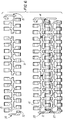
- the modular sections may form a belt of desired width in bricklayered fashion by means of an end-cap-less modular section 71.
- the belt edge modular sections 15' of this embodiment have male pivot rod retention posts 72 inserted into the adjacent wishbone journalling aperture 27 to abut the pivot rod 14.
- the flexible retention arm 33 permits the retention posts 72 to be moved aside for entry or removal of the pivot rods 14.
- the right end modular section 15'' may be different in length from the left end modular section 15' on a row of modules. With various module lengths, the bricklaying pattern can be realized. However identical modules can be used on either belt edge with 180 degree rotation to fit on the opposite ends.
- the end-cap-less modules 71 also can be made of various lengths to fill the space between the endcapped belt edge units 15', 15''.
- the belts may be bricklayered, and belts of various widths may be constructed of a minimum of only two basic modular section configurations.
Landscapes
- Engineering & Computer Science (AREA)
- Mechanical Engineering (AREA)
- Chain Conveyers (AREA)
Claims (8)
- Ein modulares Förderbandsystem umfaßt wenigstens ein Antriebszahnrad (41) mit Antriebszähnen (44, 45, 46), Zugriffsnuten (49) in den Zähnen (46) und einen Querverbindungsbalken (20) einer Moduleinheit, wobei die Zahnradantriebszähne (44, 45, 46) zum Antrieb eines Bandes dienen, das eine Vielzahl von Moduleinheiten (16, 17, 18, 19) umfaßt, von denen jede den Querverbindungsbalken (20) aufweist und für eine gelenkige Ende-an-Ende Verbindung in einer endlosen Bandkonfiguration beschaffen ist, die eine äußere Bandseite als eine Bandlasttragfläche zum Ablegen über eine Breite eines Förderbandes bildet, und eine innere Bandseite mit Antriebsflächen zur Ineingriffnahme der Zahnradantriebszähne, wobei die gelenkige Verbindung im wesentlichen zylindrische Körper (54) umfaßt, die mit einer axialen Öffnung (27') versehen sind, zum Aufnehmen und Lagern einer zylindrischen, einstückigen Drehstange (14) in einer festen Ausrichtung, um die Moduleinheiten (16, 17, 18, 19) drehbar zu verbinden, dadurch gekennzeichnet, daß die Zugriffsnuten (49) die Querverbindungsbalken (20) in einer kontaktlosen Beziehung unterbringen, wobei das innere Band mit den Antriebsflächen Zähne (26) umfaßt, die sich integral erstrecken von den zylindrischen Körpern (54) als Fortsätze, die von der gegenüberliegenden Bandseite weggerichtet sind und ebene Antriebszahnflächen (55, 56) tragen, die sich von diametral entgegengesetzten Seiten der im großen und ganzen zylindrischen Körper (54) erstrecken, wobei die ebenen Antriebszahnflächen (55, 56) anzuordnen sind zum aufeinander Einwirken mit passenden ebenen Antriebsflächen (52, 53), die sich radial erstrecken von einem Antriebszahnrad zwischen benachbarten Zähnen (26), die an der inneren Bandseite angeordnet sind, wobei der Fortsatz des Zahns (26), im wesentichen trapezförmig auszubilden ist, um die ebenen Antriebsflächen zum Eintritt sowie zum Verlassen der entsprechenden ebenen Antriebsflächen (52, 53) der Zahnradnuten zu schaffen, wobei die ineinandergreifenden Antriebsflächen im wesentlichen parallel sind, während sich die Moduleinheiten (16, 17, 18, 19) beim Einrücken des Zahnrades (41) drehen, um minimale Reibungsverluste und einen ruhigen, vibrationslosen Eintritt sowie Austritt von den Bandzähnen (26) in die Zahnradnuten (43) zum Antrieb des Bandes sicherzustellen.
- Ein modulares Förderbandsystem nach Anspruch 1, dadurch gekennzeichnet, daß die im wesentlichen zylindrischen Körper (54) zylindrische Seitenwände von unterschiedlichen Dicken/Stärken (57, 58) aufweisen, die an gegenüberliegenden Seiten der Lageröffnung (27) in einer parallel zum Band verlaufenden Ebene angeordnet sind.
- Ein modulares Förderbandsystem nach Anspruch 2, des weiteren gekennzeichnet durch eine Vielzahl der modularen Basisglieder (18, 19) mit zwei gegabelten Fingern (31, 38), die jeweils die die Drehstange lagernden Öffnungen (27) an zwei Gliedendabschnitten bilden, wobei ein Gliedendabschnitt gegenüber der ersten Drehstangenachse an dem anderen Gliedendabschnitt parallel versetzt ist, wobei die Modulglieder dadurch aus einer Anordnung von Seite-an-Seite angeordneten Elementen bestehen, die einen Teil eines Förderbandes mit abwechselnden Schaftabschnitten (31, 38) bilden, welche sich in entgegengesetzten Richtungen in jeder einer Vielzahl von Ende-an-Ende Reihen von gabelbeinförmigen Gliedern (18, 19) erstrecken, die quer über das Band von einem Bandrand zu einem gegenüberliegenden Bandrand angeordnet sind, wobei die im wesentlichen hohlzylindrischen Abschnitte in den Gliedendabschnitten von benachbarten Ende-an-Ende angeordneten Gliedern Seite-an-Seite angeordnet sind und eine Reihe von Zahnradantriebsöffnungen in dem Band bilden, um die Bandantriebszähne (44, 45, 46) des Zahnrades in Kontakt mit einem der zwei Seite-an-Seite angeordneten zylindrischen Abschnitte in den Gliedendabschnitten zu bringen bzw. zu positionieren, um dadurch eine Antriebsstruktur zum Fördern des Bandes entlang einer Bahn als Reaktion auf eine äußere Antriebskraft zu umfassen.
- Ein modulares Förderbandsystem nach Anspruch 3, des weiteren gekennzeichnet durch Stützmittel, die eine Vielzahl der Seite-an-Seite angeordneten Modulgliedern an der richtigen Stelle in einer modularen Bandeinheit integral halten, wobei die Schäfte (31) und die Verlängerungsäste zwischengeschaltete Finger (31, 38) bilden, die sich in zwei entgegengesetzten Richtungen in einer Ebene erstrecken, die durch die Finger und ihre drehstangenlagernden Öffnungen (17) verläuft.
- Ein modulares Förderbandsystem nach Anspruch 1, gekennzeichnet durch eine Antriebsverbindung mit dem Zahnrad, wobei die trapezförmigen Fortsätze (66) geformt sind für den Eintritt der Fortsätze in die Zahnradnuten sowie den Austritt aus diesen heraus in einer Antriebsbahnverbindung, die Kräfte im wesentlichen verhindert, welche das Band von dem Zahnrad wegdrängen.
- Ein modulares Förderbandsystem nach Anspruch 1, des weiteren gekennzeichnet durch Drehstangenhaltemittel (72), das an wenigstens einem Ende der Einheit durch ein Element integral gehalten ist, das eine wiederholbare Bewegung durch elastische Verformung des Drehstangenhaltemittels (72) aus einer Normalposition heraus, die verhindert, daß ein Drehstangenende aus der Einheit vorsteht, in eine gebogene Stellung, die einen Ein- oder Austritt der Drehstange (14) in die Drehstangenhalteöffnungen (27) verhindert.
- Ein modulares Förderbandsystem nach Anspruch 6, des weiteren gekennzeichnet durch eine Struktur an dem Drehstangenhaltemittel (72), die sich normalerweise in eine die Drehstange lagernde Öffnung (27) eines Modulelementes erstreckt, und aus der Öffnung (27) in einer dreidimensionalen Bewegungsbahn durch die elastische Verformung beweglich ist, um einen Zugang zu der Öffnung (27) zum Einschieben oder Entfernen einer Drehstange zu ermöglichen.
- Ein modulares Förderbandsystem nach Anspruch 7, wobei das Drehstangenhaltemittel (72) des weiteren durch ein Bandrandelement gekennzeichnet ist, das im wesentlichen in einer ebenen Bewegung zwischen der normalen und der gebogenen Stellung elastisch beweglich ist.
Applications Claiming Priority (4)
| Application Number | Priority Date | Filing Date | Title |
|---|---|---|---|
| US610751 | 1990-11-08 | ||
| US07/610,751 US5083660A (en) | 1990-11-08 | 1990-11-08 | Removably retaining pivot rods in modular plastic belts |
| US756876 | 1991-09-09 | ||
| US07/756,876 US5156262A (en) | 1990-11-08 | 1991-09-09 | Conveyor belt module drive surfaces for mating with sprocket drive surface in the hinging region |
Publications (2)
| Publication Number | Publication Date |
|---|---|
| EP0484883A1 EP0484883A1 (de) | 1992-05-13 |
| EP0484883B1 true EP0484883B1 (de) | 1996-01-10 |
Family
ID=27086346
Family Applications (1)
| Application Number | Title | Priority Date | Filing Date |
|---|---|---|---|
| EP91118842A Expired - Lifetime EP0484883B1 (de) | 1990-11-08 | 1991-11-05 | Fördersystem mit Antriebsflächen eines Förderbandmoduls, die im Scharnierbereich mit einem Antriebszahnrad zusammenwirken |
Country Status (4)
| Country | Link |
|---|---|
| US (1) | US5156262A (de) |
| EP (1) | EP0484883B1 (de) |
| CA (1) | CA2054378C (de) |
| DE (1) | DE69116314T2 (de) |
Families Citing this family (23)
| Publication number | Priority date | Publication date | Assignee | Title |
|---|---|---|---|---|
| US5215185A (en) * | 1992-09-08 | 1993-06-01 | Rexnord Corporation | Breakable molded plastic links for forming conveyor chain |
| DK125793A (da) * | 1993-11-05 | 1995-05-06 | Baeltix Maskinfabrikken As | Kædeled med låsepal for transportørkæder og transportørbånd |
| US5372248A (en) * | 1994-01-18 | 1994-12-13 | The Laitram Corporation | Radius conveyor belt |
| US5573106A (en) * | 1996-02-05 | 1996-11-12 | Rexnord Corporation | Modular conveyor chain including headed hinge pins |
| US5816390A (en) | 1996-02-05 | 1998-10-06 | Stebnicki; James C. | Conveyor pin retention system using offset openings |
| US5899322A (en) * | 1996-08-22 | 1999-05-04 | Regina-Emerson Company | Retention clip for conveyor belts |
| USD420777S (en) * | 1996-11-07 | 2000-02-15 | Maskinfabrikken Baeltix A/S | Chain link module for a conveyor belt |
| US5960937A (en) * | 1997-10-27 | 1999-10-05 | Rexnord Corporation | Conveyor with hinge pin retention plug with snap fit |
| US6345715B2 (en) | 1998-11-03 | 2002-02-12 | Kvp Falcon Plastic Belting, Inc. | Rod retention system for modular plastic conveyor belt |
| US6330941B1 (en) * | 2000-05-25 | 2001-12-18 | Habasit Ag | Radius conveyor belt |
| US6516944B2 (en) * | 2000-08-21 | 2003-02-11 | Habasit Ag | Module with alternating, offset cross-rib |
| DE10236705B9 (de) * | 2002-08-09 | 2006-06-29 | Rexroth Mecman Gmbh | Transportzahnkette mit verringertem Höhenverschleiß |
| US7097030B2 (en) * | 2004-10-19 | 2006-08-29 | Laitram, L.L.C. | Long, flexible conveyor belt modules in modular plastic conveyor belts |
| US8579104B2 (en) | 2010-05-13 | 2013-11-12 | Laitram, L.L.C. | Conveyor belt and module accommodating rod growth |
| DE102011114250A1 (de) * | 2011-09-23 | 2013-03-28 | Iwis Antriebssysteme Gmbh & Co. Kg | Förderkette |
| US8757366B2 (en) * | 2012-03-15 | 2014-06-24 | Laitram, L.L.C. | Hinge rod retainer for a modular conveyor belt |
| US9216859B2 (en) * | 2013-05-03 | 2015-12-22 | Habasit Ag | Rod retention system and method |
| US9663298B2 (en) | 2014-12-18 | 2017-05-30 | Laitram, L.L.C. | Conveyor belt module with shaped bottom surface |
| WO2017139137A1 (en) * | 2016-02-10 | 2017-08-17 | Laitram, L.L.C. | Conveyor belts with long drive pitch |
| WO2019152339A1 (en) | 2018-01-30 | 2019-08-08 | Cambridge International, Inc. | Splice system for conveyor belt |
| NL2020608B1 (en) * | 2018-03-16 | 2019-09-26 | Jonge Poerink Conveyors B V | conveyor chain Link |
| WO2021248619A1 (zh) * | 2020-06-10 | 2021-12-16 | 吴翔 | 一种网链驱动结构 |
| WO2024059066A1 (en) | 2022-09-13 | 2024-03-21 | Cambridge International, Inc. | Weldless conveyor belt systems and methods |
Citations (2)
| Publication number | Priority date | Publication date | Assignee | Title |
|---|---|---|---|---|
| EP0380202A1 (de) * | 1989-01-26 | 1990-08-01 | The Laitram Corporation | Vorrichtung und Verfahren zum zerstörungsfreien Ausbau von Gelenkstäben aus modularen Kunststoff-Förderbändern |
| EP0380201A2 (de) * | 1989-01-26 | 1990-08-01 | The Laitram Corporation | Förderbandmodul |
Family Cites Families (13)
| Publication number | Priority date | Publication date | Assignee | Title |
|---|---|---|---|---|
| GB305167A (en) * | 1928-02-01 | 1929-08-08 | Morse Chain Co | Improvements relating to drive chains |
| US2199292A (en) * | 1938-11-17 | 1940-04-30 | Link Belt Co | Heavy duty drive chain |
| US3724285A (en) * | 1972-04-17 | 1973-04-03 | J Lapeyre | Conveyor drive |
| US3980173A (en) * | 1975-10-02 | 1976-09-14 | Owens-Illinois, Inc. | Precision moving platform |
| JPS5925766Y2 (ja) * | 1976-08-16 | 1984-07-27 | 山久チエイン株式会社 | コンベヤチエ−ン |
| US4276040A (en) * | 1979-12-14 | 1981-06-30 | Rexnord Inc. | Pintle chain having extended wear barrel section and sprocket therefor |
| US4832187A (en) * | 1980-08-19 | 1989-05-23 | The Laitram Corporation | Modular center drive conveyor belt |
| US4886158B1 (en) * | 1980-08-19 | 1995-02-28 | Laitram Corp | Modular center drive conveyor belt |
| US4742907A (en) * | 1982-06-01 | 1988-05-10 | Kvp Systems, Inc. | Plastic conveyor belt |
| US4729469A (en) * | 1985-11-15 | 1988-03-08 | Lapeyre James M | Flat top conveyor belt |
| US4949838A (en) * | 1988-11-14 | 1990-08-21 | The Laitram Corporation | Apparatus and methods to allow non-destructive removal of pivot rods in modular plastic conveyor belts |
| US4953693A (en) * | 1989-01-23 | 1990-09-04 | Span Tech Corporation | Modular link conveyor system |
| US5083660A (en) * | 1990-11-08 | 1992-01-28 | The Laitram Corporation | Removably retaining pivot rods in modular plastic belts |
-
1991
- 1991-09-09 US US07/756,876 patent/US5156262A/en not_active Expired - Lifetime
- 1991-10-28 CA CA002054378A patent/CA2054378C/en not_active Expired - Fee Related
- 1991-11-05 DE DE69116314T patent/DE69116314T2/de not_active Expired - Fee Related
- 1991-11-05 EP EP91118842A patent/EP0484883B1/de not_active Expired - Lifetime
Patent Citations (2)
| Publication number | Priority date | Publication date | Assignee | Title |
|---|---|---|---|---|
| EP0380202A1 (de) * | 1989-01-26 | 1990-08-01 | The Laitram Corporation | Vorrichtung und Verfahren zum zerstörungsfreien Ausbau von Gelenkstäben aus modularen Kunststoff-Förderbändern |
| EP0380201A2 (de) * | 1989-01-26 | 1990-08-01 | The Laitram Corporation | Förderbandmodul |
Also Published As
| Publication number | Publication date |
|---|---|
| CA2054378C (en) | 2003-09-30 |
| EP0484883A1 (de) | 1992-05-13 |
| DE69116314D1 (de) | 1996-02-22 |
| DE69116314T2 (de) | 1996-05-23 |
| CA2054378A1 (en) | 1992-05-09 |
| US5156262A (en) | 1992-10-20 |
Similar Documents
| Publication | Publication Date | Title |
|---|---|---|
| EP0484883B1 (de) | Fördersystem mit Antriebsflächen eines Förderbandmoduls, die im Scharnierbereich mit einem Antriebszahnrad zusammenwirken | |
| CA1065785A (en) | Bi-directional hinged conveyor belt | |
| US4473365A (en) | Detachable link chain | |
| US4729469A (en) | Flat top conveyor belt | |
| JP4445269B2 (ja) | ロッドなしコンベヤベルト又はチェーン | |
| US6523680B2 (en) | Radius conveyor belt with structure for the prevention of pinched fingers | |
| CA1302340C (en) | Heavy duty modular conveyor belt and sprocket with unique tracking | |
| US4911682A (en) | Cambered pin CVT chain belt | |
| US4993543A (en) | Link chain belt | |
| EP0066530B1 (de) | Plattenförder-Element für einen Platten-Ketten-Förderer für geringen Auflagerdruck | |
| EP0380201B1 (de) | Förderbandmodul | |
| US4290762A (en) | Multiple link transmission chain | |
| US4882901A (en) | Detachable link chain | |
| JP5323703B2 (ja) | モジュール式プラスチックコンベアベルトの耐摩耗性ヒンジロッド | |
| US4597747A (en) | Detachable link chain | |
| US7997404B2 (en) | Conveyor belt with intermodular supported spheres | |
| CA2355532C (en) | Module with alternating, offset cross-rib | |
| JPH1111627A (ja) | 側方可撓コンベア構造 | |
| WO2003064296A1 (en) | Platform-top radius belt and modules | |
| US5125874A (en) | Long life modular link belts suitable for abrasive environments | |
| US4815271A (en) | Detachable link chain | |
| EP0333309A1 (de) | Breiter Kettenförderer | |
| JP2003034414A (ja) | 指が挟まれることを防止するための構造を備えたラジアスコンベヤベルト | |
| EP0315346B1 (de) | Gliederkette für stufenlos regelbare Getriebe mit gekrümmten Gelenkstücken | |
| USRE34688E (en) | Link chain belt |
Legal Events
| Date | Code | Title | Description |
|---|---|---|---|
| PUAI | Public reference made under article 153(3) epc to a published international application that has entered the european phase |
Free format text: ORIGINAL CODE: 0009012 |
|
| AK | Designated contracting states |
Kind code of ref document: A1 Designated state(s): DE FR GB IT NL |
|
| 17P | Request for examination filed |
Effective date: 19920626 |
|
| 17Q | First examination report despatched |
Effective date: 19931119 |
|
| ITF | It: translation for a ep patent filed | ||
| GRAA | (expected) grant |
Free format text: ORIGINAL CODE: 0009210 |
|
| AK | Designated contracting states |
Kind code of ref document: B1 Designated state(s): DE FR GB IT NL |
|
| REF | Corresponds to: |
Ref document number: 69116314 Country of ref document: DE Date of ref document: 19960222 |
|
| ET | Fr: translation filed | ||
| PLBE | No opposition filed within time limit |
Free format text: ORIGINAL CODE: 0009261 |
|
| STAA | Information on the status of an ep patent application or granted ep patent |
Free format text: STATUS: NO OPPOSITION FILED WITHIN TIME LIMIT |
|
| 26N | No opposition filed | ||
| REG | Reference to a national code |
Ref country code: GB Ref legal event code: IF02 |
|
| PGFP | Annual fee paid to national office [announced via postgrant information from national office to epo] |
Ref country code: NL Payment date: 20071010 Year of fee payment: 17 Ref country code: DE Payment date: 20071130 Year of fee payment: 17 |
|
| PGFP | Annual fee paid to national office [announced via postgrant information from national office to epo] |
Ref country code: IT Payment date: 20071116 Year of fee payment: 17 |
|
| PGFP | Annual fee paid to national office [announced via postgrant information from national office to epo] |
Ref country code: GB Payment date: 20071005 Year of fee payment: 17 Ref country code: FR Payment date: 20071105 Year of fee payment: 17 |
|
| GBPC | Gb: european patent ceased through non-payment of renewal fee |
Effective date: 20081105 |
|
| PG25 | Lapsed in a contracting state [announced via postgrant information from national office to epo] |
Ref country code: NL Free format text: LAPSE BECAUSE OF NON-PAYMENT OF DUE FEES Effective date: 20090601 |
|
| NLV4 | Nl: lapsed or anulled due to non-payment of the annual fee |
Effective date: 20090601 |
|
| PG25 | Lapsed in a contracting state [announced via postgrant information from national office to epo] |
Ref country code: IT Free format text: LAPSE BECAUSE OF NON-PAYMENT OF DUE FEES Effective date: 20081105 |
|
| REG | Reference to a national code |
Ref country code: FR Ref legal event code: ST Effective date: 20090731 |
|
| PG25 | Lapsed in a contracting state [announced via postgrant information from national office to epo] |
Ref country code: DE Free format text: LAPSE BECAUSE OF NON-PAYMENT OF DUE FEES Effective date: 20090603 |
|
| PG25 | Lapsed in a contracting state [announced via postgrant information from national office to epo] |
Ref country code: GB Free format text: LAPSE BECAUSE OF NON-PAYMENT OF DUE FEES Effective date: 20081105 |
|
| PG25 | Lapsed in a contracting state [announced via postgrant information from national office to epo] |
Ref country code: FR Free format text: LAPSE BECAUSE OF NON-PAYMENT OF DUE FEES Effective date: 20081130 |