EP0484443B1 - Improvements in or relating to sugar production apparatus - Google Patents
Improvements in or relating to sugar production apparatus Download PDFInfo
- Publication number
- EP0484443B1 EP0484443B1 EP90912399A EP90912399A EP0484443B1 EP 0484443 B1 EP0484443 B1 EP 0484443B1 EP 90912399 A EP90912399 A EP 90912399A EP 90912399 A EP90912399 A EP 90912399A EP 0484443 B1 EP0484443 B1 EP 0484443B1
- Authority
- EP
- European Patent Office
- Prior art keywords
- compartment
- fins
- shell
- fluid
- vanes
- Prior art date
- Legal status (The legal status is an assumption and is not a legal conclusion. Google has not performed a legal analysis and makes no representation as to the accuracy of the status listed.)
- Expired - Lifetime
Links
Images

Classifications
-
- C—CHEMISTRY; METALLURGY
- C13—SUGAR INDUSTRY
- C13B—PRODUCTION OF SUCROSE; APPARATUS SPECIALLY ADAPTED THEREFOR
- C13B30/00—Crystallisation; Crystallising apparatus; Separating crystals from mother liquors ; Evaporating or boiling sugar juice
- C13B30/02—Crystallisation; Crystallising apparatus
- C13B30/022—Continuous processes, apparatus therefor
- C13B30/023—Continuous processes, apparatus therefor having rotatable means for agitation or transportation
-
- B—PERFORMING OPERATIONS; TRANSPORTING
- B01—PHYSICAL OR CHEMICAL PROCESSES OR APPARATUS IN GENERAL
- B01D—SEPARATION
- B01D9/00—Crystallisation
- B01D9/0018—Evaporation of components of the mixture to be separated
- B01D9/0022—Evaporation of components of the mixture to be separated by reducing pressure
-
- B—PERFORMING OPERATIONS; TRANSPORTING
- B01—PHYSICAL OR CHEMICAL PROCESSES OR APPARATUS IN GENERAL
- B01D—SEPARATION
- B01D9/00—Crystallisation
- B01D9/0018—Evaporation of components of the mixture to be separated
- B01D9/0031—Evaporation of components of the mixture to be separated by heating
-
- B—PERFORMING OPERATIONS; TRANSPORTING
- B01—PHYSICAL OR CHEMICAL PROCESSES OR APPARATUS IN GENERAL
- B01D—SEPARATION
- B01D9/00—Crystallisation
- B01D9/0036—Crystallisation on to a bed of product crystals; Seeding
Definitions
- This invention concerns improvements in or relating to sugar production apparatus and particularly to evaporators where crystalline sugar is prepared from sugar solution.
- Sugar production apparatus includes both evaporators and cooling crystallisers.
- An example is disclosed in DE-A-543328 wherein heated fins are mounted for rotation on a shaft which extends through a plurality of compartments in the crystalliser shell (cf. also preamble of claim 1).
- An example of a batch evaporator, in which sugar is processed in successive batches, is disclosed in GB-A-1190243. The formation of sugar crystals on the evaporator walls and other components is again a disadvantage because such crystal formation reduces the efficiency of the apparatus.
- sugar production apparatus including a generally longitudinally extending shell having an inlet and an outlet towards respective ends thereof, at least part of the shell being partitioned between the inlet and the outlet into a plurality of transversely extending compartments by spaced partitions over which, in use, fluid may flow from the inlet, from each compartment to the adjacent downstream compartment, to the outlet, at least one heating fin for evaporative boiling of the fluid extending transversely into each compartment, and at least one rotatable shaft having an axis extending longitudinally through the shell and being provided with vanes, characterised in that each fin is steam heated and is supported below upper edges of the partitions at such spaced locations on the shell as to extend from a location below the shaft at the bottom of the shell to a location above the level of the longitudinal axis of the shaft, and to define a gap between the fin and the shell substantially along the whole length of the fin, and the vanes of the rotatable, longitudinally extending shaft pass below the upper edges of the partitions and over the surface
- a pair of the rotatable shafts are provided in a parallel relation, the vanes on one shaft being staggered with respect to the vanes on the other shaft so that they inter-mesh.
- the number of fins in each of the compartments increases.
- the fins may be steam heated, and at least one pair of the fins may be arranged in each compartment, the fins extending towards each other from opposed sides of the shell.
- Outer walls of the shell at the location of each compartment may be steam heated, and also the or each shaft may be steam heated. Further, the vanes may be steam heated.
- each partition is provided with a weir in an edge to control fluid passing thereover.
- Means may be provided for maintaining the shell at sub-atmospheric pressure, and means may be provided for introducing make-up fluid into the compartments, the fluid introduction means comprising, for example, nozzles located above the compartments.
- the nozzles may deliver a curtain of make-up fluid or a spray.
- the shell may also be provided with vapour extraction means.
- An evaporator in the of a vacuum pan comprises a shell 10 having an arcuate top 12 incorporating sight glasses 14, illumination means 16 and a hatch 18 on a manway 20, none of which form part of the present invention and will not be described in detail.
- the top 12 is connected to a base 24 by straight sided walls 22, the base comprising a centre flat portion 26 and two upwardly arcuate walls 28.
- the latter are each provided with a spaced, external wall 30 whereby heating steam may be supplied to the spacings between the walls 28, 30, to provide a heating jacket.
- Two hollow rotatable shafts 32 extend through the evaporator from an end wall 34 to an opposed end wall 36 in a parallel relation.
- Each shaft passes through a plurality of spaced partitions 38 which extend from the base of the evaporator to a point just above the half-way mark and are each provided at one side of an upper edge with a weir 40 so that sugar and water solution, or massecuite, may flow from an inlet compartment 42 defined between the end wall 36 and the first partition 38, to a neighbouring compartment 44 and so on to the end compartment 46, seven compartments in all being provided, the compartments increasing in volume from inlet to outlet.
- Each compartment includes at least one pair of hollow fins 50 each of the fins being supported from a respective one of the arcuate walls 28 and the base 26 but spaced therefrom by a gap 56.
- the fins 50 are hollow such that heating steam can pass therethrough from an inlet manifold 52 to an outlet manifold 54.
- the number of fins 50 increases from the inlet compartment 42 which has one pair, to the outlet compartment 46 which has eight pairs.
- Each shaft 32 has a plurality of vanes 58 radially extending therefrom. The vanes are arranged in spaced apart sets of six, and each set, on rotation of the respective shaft, sweeps the space between adjacent fins 50 or adjacent fins and partitions.
- the vanes 58 on one shaft are staggered with respect to those on the other shaft so that they "intermesh" to ensure good agitation of the massecuite in each compartment.
- a vapour extraction arrangement 60 is provided in the roof 12 of the evaporator adjacent the outlet end wall 34, and supported from the roof 12 there are provided a plurality of syrup introduction nozzles 62 for supplying a curtain of syrup into the compartments.
- the nozzles 64 above the outlet compartment 46 supply sprays of syrup.
- Also suspended from the roof 12 are a plurality of sprays 66 for spraying syrup onto the surface of the massecuite, the partitions, and the evaporator walls to wash any crystals forming on the walls into the massecuite.
- massecuite with seed crystals therein fills each compartment and steam is supplied to the fins 50 and to the external heating jacket. Water evaporates from the massecuite thereby increasing the degree of super saturation and causing more sugar to deposit onto the surface of the crystals present.
- the agitating action of the vanes 58 in each compartment causes an even dispersal of the sugar crystals and controls their size. As the vanes 58 pass close to the fins 50 they ensure that the massecuite in contact with the fins and partitions is always in motion, thus reducing the tendancy for crystals to form on the fins or settle out of the massecuite. Similarly the tips of the vanes sweep close to the arcuate walls 24 and reduce the tendancy for crystals to form on these walls.
- heating steam can be fed to the hollow shafts 32 to increase the evaporation effect within the massecuite and to heat the vanes 58 to reduce the formation of crystals thereon.
- the vanes themselves may have steam passages therethrough and may have an oval cross-section.
- the vanes of each set may be arranged in the same plane or may be in a spiral arrangement to further enhance agitation.
- the number of compartments can be varied and different means can be provided for making up the massecuite in each compartment.
- the nozzles 62 can be replaced by feed means in the base of each compartment.
- the base of the shell may be curved instead of flat over the portion 26.
Landscapes
- Chemical & Material Sciences (AREA)
- Crystallography & Structural Chemistry (AREA)
- Chemical Kinetics & Catalysis (AREA)
- Life Sciences & Earth Sciences (AREA)
- Biochemistry (AREA)
- Organic Chemistry (AREA)
- Physics & Mathematics (AREA)
- Thermal Sciences (AREA)
- Saccharide Compounds (AREA)
- Vaporization, Distillation, Condensation, Sublimation, And Cold Traps (AREA)
- Seasonings (AREA)
- Confectionery (AREA)
- Coloring Foods And Improving Nutritive Qualities (AREA)
- External Artificial Organs (AREA)
Abstract
Description
- This invention concerns improvements in or relating to sugar production apparatus and particularly to evaporators where crystalline sugar is prepared from sugar solution.
- Sugar production apparatus includes both evaporators and cooling crystallisers. An example is disclosed in DE-A-543328 wherein heated fins are mounted for rotation on a shaft which extends through a plurality of compartments in the crystalliser shell (cf. also preamble of claim 1). An example of a batch evaporator, in which sugar is processed in successive batches, is disclosed in GB-A-1190243. The formation of sugar crystals on the evaporator walls and other components is again a disadvantage because such crystal formation reduces the efficiency of the apparatus.
- It is an object of the present invention to provide a continuous evaporator in which the disadvantages of prior evaporators are obviated or mitigated.
- According to the present invention there is provided sugar production apparatus including a generally longitudinally extending shell having an inlet and an outlet towards respective ends thereof, at least part of the shell being partitioned between the inlet and the outlet into a plurality of transversely extending compartments by spaced partitions over which, in use, fluid may flow from the inlet, from each compartment to the adjacent downstream compartment, to the outlet, at least one heating fin for evaporative boiling of the fluid extending transversely into each compartment, and at least one rotatable shaft having an axis extending longitudinally through the shell and being provided with vanes, characterised in that each fin is steam heated and is supported below upper edges of the partitions at such spaced locations on the shell as to extend from a location below the shaft at the bottom of the shell to a location above the level of the longitudinal axis of the shaft, and to define a gap between the fin and the shell substantially along the whole length of the fin, and the vanes of the rotatable, longitudinally extending shaft pass below the upper edges of the partitions and over the surface of the respective fins to be wholly immersed in the fluid and agitate the fluid to be evaporated within the compartments, including the fluid at the surfaces of the fins and the fluid in the gaps between the fins and the shell.
- Preferably a pair of the rotatable shafts are provided in a parallel relation, the vanes on one shaft being staggered with respect to the vanes on the other shaft so that they inter-mesh.
- Preferably also, in a direction from inlet to outlet, the number of fins in each of the compartments increases. The fins may be steam heated, and at least one pair of the fins may be arranged in each compartment, the fins extending towards each other from opposed sides of the shell.
- Outer walls of the shell at the location of each compartment may be steam heated, and also the or each shaft may be steam heated. Further, the vanes may be steam heated.
- Preferably each partition is provided with a weir in an edge to control fluid passing thereover.
- Means may be provided for maintaining the shell at sub-atmospheric pressure, and means may be provided for introducing make-up fluid into the compartments, the fluid introduction means comprising, for example, nozzles located above the compartments. The nozzles may deliver a curtain of make-up fluid or a spray. The shell may also be provided with vapour extraction means.
- An embodiment of the present invention will now be described by way of example only with reference to the accompanying drawings in which:-
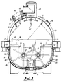
- Fig 1 is a transverse elevation through an evaporator and;
- Fig 2 is a longitudinal elevation.
- An evaporator in the of a vacuum pan comprises a
shell 10 having anarcuate top 12 incorporating sight glasses 14, illumination means 16 and ahatch 18 on amanway 20, none of which form part of the present invention and will not be described in detail. The top 12 is connected to abase 24 by straightsided walls 22, the base comprising a centreflat portion 26 and two upwardlyarcuate walls 28. The latter are each provided with a spaced,external wall 30 whereby heating steam may be supplied to the spacings between thewalls - Two hollow
rotatable shafts 32 extend through the evaporator from an end wall 34 to an opposed end wall 36 in a parallel relation. Each shaft passes through a plurality of spacedpartitions 38 which extend from the base of the evaporator to a point just above the half-way mark and are each provided at one side of an upper edge with aweir 40 so that sugar and water solution, or massecuite, may flow from an inlet compartment 42 defined between the end wall 36 and thefirst partition 38, to a neighbouring compartment 44 and so on to the end compartment 46, seven compartments in all being provided, the compartments increasing in volume from inlet to outlet. - Each compartment includes at least one pair of
hollow fins 50 each of the fins being supported from a respective one of thearcuate walls 28 and thebase 26 but spaced therefrom by agap 56. Thefins 50 are hollow such that heating steam can pass therethrough from aninlet manifold 52 to anoutlet manifold 54. The number offins 50 increases from the inlet compartment 42 which has one pair, to the outlet compartment 46 which has eight pairs. Eachshaft 32 has a plurality ofvanes 58 radially extending therefrom. The vanes are arranged in spaced apart sets of six, and each set, on rotation of the respective shaft, sweeps the space betweenadjacent fins 50 or adjacent fins and partitions. Thevanes 58 on one shaft are staggered with respect to those on the other shaft so that they "intermesh" to ensure good agitation of the massecuite in each compartment. - A
vapour extraction arrangement 60 is provided in theroof 12 of the evaporator adjacent the outlet end wall 34, and supported from theroof 12 there are provided a plurality ofsyrup introduction nozzles 62 for supplying a curtain of syrup into the compartments. The nozzles 64 above the outlet compartment 46 supply sprays of syrup. Also suspended from theroof 12 are a plurality ofsprays 66 for spraying syrup onto the surface of the massecuite, the partitions, and the evaporator walls to wash any crystals forming on the walls into the massecuite. - In operation, massecuite with seed crystals therein fills each compartment and steam is supplied to the
fins 50 and to the external heating jacket. Water evaporates from the massecuite thereby increasing the degree of super saturation and causing more sugar to deposit onto the surface of the crystals present. The agitating action of thevanes 58 in each compartment causes an even dispersal of the sugar crystals and controls their size. As thevanes 58 pass close to thefins 50 they ensure that the massecuite in contact with the fins and partitions is always in motion, thus reducing the tendancy for crystals to form on the fins or settle out of the massecuite. Similarly the tips of the vanes sweep close to thearcuate walls 24 and reduce the tendancy for crystals to form on these walls. It is known that crystals tend to form at sharp angles and consequently thegap 56 between the fins and thearcuate walls 28 is provided to encourage circulation along the length of thewall 28 thereby reducing crystal formation at this point. The introduction of make-up syrup through thenozzles 62 increases the volume of massecuite in each compartment and concentrated massecuite flows over therespective weir 40 into the adjacent downstream compartment where further evaporation takes place, the more concentrated massecuite then passing to the next compartment, and being in its most concentrated state in the end compartment 46 from which it leaves the apparatus for further processing. The water vapour separated from the massecuite is exhausted from thesub-atmospheric shell 10 by theextractor assembly 60. - Various modifications can be made without departing from the scope of the invention. For example heating steam can be fed to the
hollow shafts 32 to increase the evaporation effect within the massecuite and to heat thevanes 58 to reduce the formation of crystals thereon. The vanes themselves may have steam passages therethrough and may have an oval cross-section. The vanes of each set may be arranged in the same plane or may be in a spiral arrangement to further enhance agitation. - The number of compartments can be varied and different means can be provided for making up the massecuite in each compartment. For example the
nozzles 62 can be replaced by feed means in the base of each compartment. The base of the shell may be curved instead of flat over theportion 26.
Claims (11)
- Sugar production apparatus including a generally longitudinally extending shell (10) having an inlet and an outlet towards respective ends thereof, at least part of the shell (10) being partitioned between the inlet and the outlet into a plurality of transversely extending compartments (42-46) by spaced partitions (38) over which, in use, fluid may flow from the inlet, from each compartment to the adjacent downstream compartment, to the outlet, at least one heating fin (50) for evaporative boiling of the fluid extending transversely into each compartment, and at least one rotatable shaft (32) having an axis extending longitudinally through the shell (10) and being provided with vanes (58), characterised in that each fin (50) is steam heated and is supported below upper edges of the partitions (38) at such spaced locations on the shell (10) as to extend from a location below the shaft (32) at the bottom of the shell to a location above the level of the longitudinal axis of the shaft, and to define a gap (56) between the fin (50) and the shell (10) substantially along the whole length of the fin (50), and the vanes (58) of the rotatable, longitudinally extending shaft (32) pass below the upper edges of the partitions (38) and over the surface of the respective fins (50) to be wholly immersed in the fluid and agitate the fluid to be evaporated within the compartments (42-46), including the fluid at the surfaces of the fins (50) and the fluid in the gaps (56) between the fins (50) and the shell (10).
- Apparatus according to Claim 1, characterised in that a pair of the rotatable shafts (32) are provided in a parallel relation, the vanes (58) on one shaft being staggered with respect to the vanes (58) on the other shaft so that they inter-mesh.
- Apparatus according to any of Claims 1 to 2, characterised in that in a direction from inlet to outlet, the number of fins (50) in each of the compartments increases.
- Apparatus according to any of the preceding Claims, characterised in that at least one pair of the fins (50) is provided in each compartment (42-46), the fins extending towards each other from opposed sides of the shell (10).
- Apparatus according to any of the preceding Claims, characterised in that outer walls of the shell (10) at the location of each compartment are steam heated.
- Apparatus according to any of the preceding Claims, characterised in that the or each shaft (32) is steam heated.
- Apparatus according to any of the preceding Claims, characterised in that the vanes (58) are steam heated.
- Apparatus according to any of the preceding Claims, characterised in that each partition (38) is provided with a weir (40) in an edge to control fluid passing thereover.
- Apparatus according to any of the preceding Claims, characterised in that nozzles (62) are located above the compartments (42-46) for introducing make-up fluid into the compartments.
- Apparatus according to Claim 9, characterised in that the nozzles (62) are adapted to deliver a curtain of make-up fluid.
- Apparatus according to claim 9, characterised in that the nozzles (62) are adapted to deliver a spray.
Applications Claiming Priority (3)
| Application Number | Priority Date | Filing Date | Title |
|---|---|---|---|
| GB8917313 | 1989-07-28 | ||
| GB898917313A GB8917313D0 (en) | 1989-07-28 | 1989-07-28 | Improvements in or relating to sugar production apparatus |
| PCT/GB1990/001172 WO1991001785A1 (en) | 1989-07-28 | 1990-07-27 | Improvements in or relating to sugar production apparatus |
Publications (2)
| Publication Number | Publication Date |
|---|---|
| EP0484443A1 EP0484443A1 (en) | 1992-05-13 |
| EP0484443B1 true EP0484443B1 (en) | 1996-08-28 |
Family
ID=10660794
Family Applications (1)
| Application Number | Title | Priority Date | Filing Date |
|---|---|---|---|
| EP90912399A Expired - Lifetime EP0484443B1 (en) | 1989-07-28 | 1990-07-27 | Improvements in or relating to sugar production apparatus |
Country Status (16)
| Country | Link |
|---|---|
| US (1) | US5201957A (en) |
| EP (1) | EP0484443B1 (en) |
| JP (1) | JP2805110B2 (en) |
| AT (1) | ATE141818T1 (en) |
| AU (1) | AU655756B2 (en) |
| BR (1) | BR9007562A (en) |
| CS (1) | CS277640B6 (en) |
| DE (1) | DE69028307T2 (en) |
| DK (1) | DK0484443T3 (en) |
| ES (1) | ES2091247T3 (en) |
| GB (1) | GB8917313D0 (en) |
| IN (1) | IN176661B (en) |
| MY (1) | MY107262A (en) |
| PL (1) | PL164482B1 (en) |
| WO (1) | WO1991001785A1 (en) |
| ZA (1) | ZA905913B (en) |
Families Citing this family (5)
| Publication number | Priority date | Publication date | Assignee | Title |
|---|---|---|---|---|
| AU645368B2 (en) * | 1990-11-28 | 1994-01-13 | Csr Limited | Process and apparatus for the crystallisation of sugar |
| DE19841323C1 (en) * | 1998-09-10 | 2000-02-24 | Braunschweigische Masch Bau | Sugar manufacture evaporator process tank has a mixer unit driving the flow of liquid horizontally over heat exchanger, enhancing efficiency with lower cost |
| BRMU8603056U2 (en) * | 2006-03-30 | 2009-02-03 | Spray Engineering Devices Ltd | vacuum container mechanical circulator assembly |
| GB2510160A (en) * | 2013-01-27 | 2014-07-30 | Ide Technologies Ltd | Evaporator for treating water |
| USD802352S1 (en) * | 2016-03-31 | 2017-11-14 | Vermont Evaporator Company, LLC | Barrel evaporator |
Family Cites Families (6)
| Publication number | Priority date | Publication date | Assignee | Title |
|---|---|---|---|---|
| DE543328C (en) * | 1928-10-11 | 1932-02-04 | Werkspoor Nv | Device for cooling or heating sugar filling masses |
| DE1047128B (en) * | 1957-08-08 | 1958-12-18 | Maizena Werke G M B H Deutsche | Method and device for filling crystallizers with concentrated sugar juices |
| FR1324801A (en) * | 1962-06-12 | 1963-04-19 | Sueddeutsche Zucker Ag | Process and installation for cooking and crystallizing sugar solutions |
| FR1494289A (en) * | 1966-07-28 | 1967-09-08 | Fives Lille Cail | Method and device for preventing fouling of walls in continuously operating evaporative crystallization apparatus |
| GB1190243A (en) * | 1967-04-29 | 1970-04-29 | Fletcher And Stewart Ltd | Improvements in Evaporators |
| GB1381766A (en) * | 1972-08-24 | 1975-01-29 | Hyesons Sugar Mills Ltd | Crystallization of sugar |
-
1989
- 1989-07-28 GB GB898917313A patent/GB8917313D0/en active Pending
-
1990
- 1990-07-27 MY MYPI90001259A patent/MY107262A/en unknown
- 1990-07-27 ES ES90912399T patent/ES2091247T3/en not_active Expired - Lifetime
- 1990-07-27 DK DK90912399.4T patent/DK0484443T3/en active
- 1990-07-27 WO PCT/GB1990/001172 patent/WO1991001785A1/en active IP Right Grant
- 1990-07-27 AT AT90912399T patent/ATE141818T1/en not_active IP Right Cessation
- 1990-07-27 BR BR909007562A patent/BR9007562A/en not_active IP Right Cessation
- 1990-07-27 EP EP90912399A patent/EP0484443B1/en not_active Expired - Lifetime
- 1990-07-27 JP JP2511479A patent/JP2805110B2/en not_active Expired - Lifetime
- 1990-07-27 CS CS903744A patent/CS277640B6/en not_active IP Right Cessation
- 1990-07-27 IN IN614MA1990 patent/IN176661B/en unknown
- 1990-07-27 US US07/809,539 patent/US5201957A/en not_active Expired - Fee Related
- 1990-07-27 PL PL90286245A patent/PL164482B1/en unknown
- 1990-07-27 DE DE69028307T patent/DE69028307T2/en not_active Expired - Fee Related
- 1990-07-27 AU AU61673/90A patent/AU655756B2/en not_active Ceased
- 1990-07-27 ZA ZA905913A patent/ZA905913B/en unknown
Also Published As
| Publication number | Publication date |
|---|---|
| DE69028307T2 (en) | 1997-01-23 |
| JPH05501055A (en) | 1993-03-04 |
| MY107262A (en) | 1995-10-31 |
| CS374490A3 (en) | 1992-08-12 |
| GB8917313D0 (en) | 1989-09-13 |
| PL286245A1 (en) | 1991-05-06 |
| CS277640B6 (en) | 1993-03-17 |
| AU6167390A (en) | 1991-03-11 |
| AU655756B2 (en) | 1995-01-12 |
| JP2805110B2 (en) | 1998-09-30 |
| DK0484443T3 (en) | 1996-12-09 |
| DE69028307D1 (en) | 1996-10-02 |
| EP0484443A1 (en) | 1992-05-13 |
| ATE141818T1 (en) | 1996-09-15 |
| ZA905913B (en) | 1991-05-29 |
| BR9007562A (en) | 1992-06-23 |
| WO1991001785A1 (en) | 1991-02-21 |
| PL164482B1 (en) | 1994-08-31 |
| ES2091247T3 (en) | 1996-11-01 |
| US5201957A (en) | 1993-04-13 |
| IN176661B (en) | 1996-08-17 |
Similar Documents
| Publication | Publication Date | Title |
|---|---|---|
| US3627582A (en) | Continuous crystallizing apparatus for sugar-bearing liquor | |
| EP0484443B1 (en) | Improvements in or relating to sugar production apparatus | |
| US3879215A (en) | Compartmentalized vacuum pan for crystallization of sugar | |
| US3342039A (en) | Separation systems and apparatus | |
| US2071624A (en) | Heat transfer apparatus | |
| US3622387A (en) | Evaporator or cooking apparatus | |
| US4038129A (en) | Method and apparatus for concentrating liquids | |
| US4082606A (en) | Evaporation apparatus | |
| US1536894A (en) | Evaporating apparatus | |
| GB1268779A (en) | Multi-effect evaporator | |
| US3424221A (en) | Apparatus and method for continuous crystallization by evaporation | |
| US4256536A (en) | Evaporator | |
| US3521605A (en) | Forced recirculation evaporator | |
| US2822039A (en) | Evaporators-condensers | |
| US1644161A (en) | Process for crystallizing liquids | |
| US1982978A (en) | Apparatus for crystallizing solutions by evaporation or cooling | |
| US409572A (en) | Apparatus for evaporating liquids | |
| JPH01139101A (en) | Crystallizer | |
| US709172A (en) | Vacuum evaporating apparatus. | |
| EP0172965A1 (en) | Continuous pan crystallizer | |
| US1615151A (en) | Apparatus for crystallizing liquids | |
| US472209A (en) | Vacuum-pan | |
| SU602155A2 (en) | Foodstuff defreezing arrangement | |
| JPH0236281B2 (en) | TADANSHIKIJOHATSUSHOSEKISOCHI | |
| RU2105816C1 (en) | Apparatus for scalding of beet cossettes |
Legal Events
| Date | Code | Title | Description |
|---|---|---|---|
| PUAI | Public reference made under article 153(3) epc to a published international application that has entered the european phase |
Free format text: ORIGINAL CODE: 0009012 |
|
| 17P | Request for examination filed |
Effective date: 19920122 |
|
| AK | Designated contracting states |
Kind code of ref document: A1 Designated state(s): AT BE CH DE DK ES FR GB IT LI LU NL SE |
|
| 17Q | First examination report despatched |
Effective date: 19930705 |
|
| GRAH | Despatch of communication of intention to grant a patent |
Free format text: ORIGINAL CODE: EPIDOS IGRA |
|
| GRAH | Despatch of communication of intention to grant a patent |
Free format text: ORIGINAL CODE: EPIDOS IGRA |
|
| GRAA | (expected) grant |
Free format text: ORIGINAL CODE: 0009210 |
|
| GRAG | Despatch of communication of intention to grant |
Free format text: ORIGINAL CODE: EPIDOS AGRA |
|
| AK | Designated contracting states |
Kind code of ref document: B1 Designated state(s): AT BE CH DE DK ES FR GB IT LI LU NL SE |
|
| REF | Corresponds to: |
Ref document number: 141818 Country of ref document: AT Date of ref document: 19960915 Kind code of ref document: T |
|
| ITF | It: translation for a ep patent filed |
Owner name: GUZZI E RAVIZZA S.R.L. |
|
| REF | Corresponds to: |
Ref document number: 69028307 Country of ref document: DE Date of ref document: 19961002 |
|
| REG | Reference to a national code |
Ref country code: CH Ref legal event code: NV Representative=s name: ARDIN & CIE S.A. |
|
| REG | Reference to a national code |
Ref country code: ES Ref legal event code: FG2A Ref document number: 2091247 Country of ref document: ES Kind code of ref document: T3 |
|
| ET | Fr: translation filed | ||
| REG | Reference to a national code |
Ref country code: DK Ref legal event code: T3 |
|
| PLBE | No opposition filed within time limit |
Free format text: ORIGINAL CODE: 0009261 |
|
| STAA | Information on the status of an ep patent application or granted ep patent |
Free format text: STATUS: NO OPPOSITION FILED WITHIN TIME LIMIT |
|
| 26N | No opposition filed | ||
| PGFP | Annual fee paid to national office [announced via postgrant information from national office to epo] |
Ref country code: SE Payment date: 20000724 Year of fee payment: 11 |
|
| PGFP | Annual fee paid to national office [announced via postgrant information from national office to epo] |
Ref country code: DK Payment date: 20000725 Year of fee payment: 11 |
|
| PGFP | Annual fee paid to national office [announced via postgrant information from national office to epo] |
Ref country code: AT Payment date: 20000726 Year of fee payment: 11 |
|
| PGFP | Annual fee paid to national office [announced via postgrant information from national office to epo] |
Ref country code: NL Payment date: 20000731 Year of fee payment: 11 Ref country code: LU Payment date: 20000731 Year of fee payment: 11 |
|
| PGFP | Annual fee paid to national office [announced via postgrant information from national office to epo] |
Ref country code: CH Payment date: 20000808 Year of fee payment: 11 Ref country code: BE Payment date: 20000808 Year of fee payment: 11 |
|
| PGFP | Annual fee paid to national office [announced via postgrant information from national office to epo] |
Ref country code: GB Payment date: 20010723 Year of fee payment: 12 |
|
| PGFP | Annual fee paid to national office [announced via postgrant information from national office to epo] |
Ref country code: FR Payment date: 20010726 Year of fee payment: 12 |
|
| PG25 | Lapsed in a contracting state [announced via postgrant information from national office to epo] |
Ref country code: LU Free format text: LAPSE BECAUSE OF NON-PAYMENT OF DUE FEES Effective date: 20010727 Ref country code: DK Free format text: LAPSE BECAUSE OF NON-PAYMENT OF DUE FEES Effective date: 20010727 Ref country code: AT Free format text: LAPSE BECAUSE OF NON-PAYMENT OF DUE FEES Effective date: 20010727 |
|
| PG25 | Lapsed in a contracting state [announced via postgrant information from national office to epo] |
Ref country code: SE Free format text: LAPSE BECAUSE OF NON-PAYMENT OF DUE FEES Effective date: 20010728 |
|
| PGFP | Annual fee paid to national office [announced via postgrant information from national office to epo] |
Ref country code: DE Payment date: 20010730 Year of fee payment: 12 |
|
| PG25 | Lapsed in a contracting state [announced via postgrant information from national office to epo] |
Ref country code: LI Free format text: LAPSE BECAUSE OF NON-PAYMENT OF DUE FEES Effective date: 20010731 Ref country code: CH Free format text: LAPSE BECAUSE OF NON-PAYMENT OF DUE FEES Effective date: 20010731 Ref country code: BE Free format text: LAPSE BECAUSE OF NON-PAYMENT OF DUE FEES Effective date: 20010731 |
|
| PGFP | Annual fee paid to national office [announced via postgrant information from national office to epo] |
Ref country code: ES Payment date: 20010731 Year of fee payment: 12 |
|
| REG | Reference to a national code |
Ref country code: GB Ref legal event code: IF02 |
|
| BERE | Be: lapsed |
Owner name: FLETCHER SMITH LTD Effective date: 20010731 |
|
| PG25 | Lapsed in a contracting state [announced via postgrant information from national office to epo] |
Ref country code: NL Free format text: LAPSE BECAUSE OF NON-PAYMENT OF DUE FEES Effective date: 20020201 |
|
| EUG | Se: european patent has lapsed |
Ref document number: 90912399.4 |
|
| REG | Reference to a national code |
Ref country code: CH Ref legal event code: PL |
|
| REG | Reference to a national code |
Ref country code: DK Ref legal event code: EBP |
|
| NLV4 | Nl: lapsed or anulled due to non-payment of the annual fee |
Effective date: 20020201 |
|
| PG25 | Lapsed in a contracting state [announced via postgrant information from national office to epo] |
Ref country code: GB Free format text: LAPSE BECAUSE OF NON-PAYMENT OF DUE FEES Effective date: 20020727 |
|
| PG25 | Lapsed in a contracting state [announced via postgrant information from national office to epo] |
Ref country code: ES Free format text: LAPSE BECAUSE OF NON-PAYMENT OF DUE FEES Effective date: 20020728 |
|
| PG25 | Lapsed in a contracting state [announced via postgrant information from national office to epo] |
Ref country code: DE Free format text: LAPSE BECAUSE OF NON-PAYMENT OF DUE FEES Effective date: 20030201 |
|
| GBPC | Gb: european patent ceased through non-payment of renewal fee |
Effective date: 20020727 |
|
| PG25 | Lapsed in a contracting state [announced via postgrant information from national office to epo] |
Ref country code: FR Free format text: LAPSE BECAUSE OF NON-PAYMENT OF DUE FEES Effective date: 20030331 |
|
| REG | Reference to a national code |
Ref country code: FR Ref legal event code: ST |
|
| REG | Reference to a national code |
Ref country code: ES Ref legal event code: FD2A Effective date: 20030811 |
|
| PG25 | Lapsed in a contracting state [announced via postgrant information from national office to epo] |
Ref country code: IT Free format text: LAPSE BECAUSE OF NON-PAYMENT OF DUE FEES Effective date: 20050727 |