EP0484207B1 - Méthode pour favoriser la production d'effluents d'une zone de production - Google Patents
Méthode pour favoriser la production d'effluents d'une zone de production Download PDFInfo
- Publication number
- EP0484207B1 EP0484207B1 EP91402833A EP91402833A EP0484207B1 EP 0484207 B1 EP0484207 B1 EP 0484207B1 EP 91402833 A EP91402833 A EP 91402833A EP 91402833 A EP91402833 A EP 91402833A EP 0484207 B1 EP0484207 B1 EP 0484207B1
- Authority
- EP
- European Patent Office
- Prior art keywords
- production
- tube
- opening
- depression
- well
- Prior art date
- Legal status (The legal status is an assumption and is not a legal conclusion. Google has not performed a legal analysis and makes no representation as to the accuracy of the status listed.)
- Expired - Lifetime
Links
- 238000004519 manufacturing process Methods 0.000 title claims description 45
- 238000000034 method Methods 0.000 title claims description 16
- 239000012530 fluid Substances 0.000 title 1
- 230000007423 decrease Effects 0.000 claims description 3
- 230000004936 stimulating effect Effects 0.000 claims 1
- 238000005086 pumping Methods 0.000 description 8
- 238000010408 sweeping Methods 0.000 description 6
- 230000015572 biosynthetic process Effects 0.000 description 4
- 238000005755 formation reaction Methods 0.000 description 4
- 238000009825 accumulation Methods 0.000 description 3
- 230000004913 activation Effects 0.000 description 3
- 230000001105 regulatory effect Effects 0.000 description 3
- 230000000694 effects Effects 0.000 description 2
- 238000009434 installation Methods 0.000 description 2
- 238000011084 recovery Methods 0.000 description 2
- 230000009471 action Effects 0.000 description 1
- 230000033228 biological regulation Effects 0.000 description 1
- 230000007246 mechanism Effects 0.000 description 1
- 230000004048 modification Effects 0.000 description 1
- 238000012986 modification Methods 0.000 description 1
- 239000003208 petroleum Substances 0.000 description 1
- 230000001737 promoting effect Effects 0.000 description 1
- XLYOFNOQVPJJNP-UHFFFAOYSA-N water Substances O XLYOFNOQVPJJNP-UHFFFAOYSA-N 0.000 description 1
Images

Classifications
-
- E—FIXED CONSTRUCTIONS
- E21—EARTH OR ROCK DRILLING; MINING
- E21B—EARTH OR ROCK DRILLING; OBTAINING OIL, GAS, WATER, SOLUBLE OR MELTABLE MATERIALS OR A SLURRY OF MINERALS FROM WELLS
- E21B43/00—Methods or apparatus for obtaining oil, gas, water, soluble or meltable materials or a slurry of minerals from wells
- E21B43/12—Methods or apparatus for controlling the flow of the obtained fluid to or in wells
- E21B43/121—Lifting well fluids
-
- E—FIXED CONSTRUCTIONS
- E21—EARTH OR ROCK DRILLING; MINING
- E21B—EARTH OR ROCK DRILLING; OBTAINING OIL, GAS, WATER, SOLUBLE OR MELTABLE MATERIALS OR A SLURRY OF MINERALS FROM WELLS
- E21B43/00—Methods or apparatus for obtaining oil, gas, water, soluble or meltable materials or a slurry of minerals from wells
- E21B43/30—Specific pattern of wells, e.g. optimising the spacing of wells
- E21B43/305—Specific pattern of wells, e.g. optimising the spacing of wells comprising at least one inclined or horizontal well
Definitions
- the present invention relates to a method for promoting, by creating a depression, the production of effluents from a production zone crossed by at least one deviated well or drain, such as an oil zone.
- deviated well designates any well of which at least part is substantially horizontal or slightly inclined relative to the horizontal.
- One of the advantages of deviated wells is to allow better sweeping of the petroleum effluents contained in the formations crossed and therefore to improve recovery.
- Optimal recovery for a given scanning mechanism, is obtained when the scanning front moves parallel to the deflected drain.
- the regularity of the sweeping front is sometimes difficult to maintain due to heterogeneities of the reservoir, such as fractures or channels etc., modifications to the geometry of the drain or even disturbances linked to flows in the drain such as pressure drops .
- a known method for sweeping a production area is to descend a pumping device there to suck out the effluents when the pressure in the formation becomes insufficient.
- the deviated well which crosses it is equipped with a casing or casing tube which is perforated in its part which crosses the production area.
- a production tube is lowered into the area to be activated.
- a pump is interposed on the tube so as to create a vacuum.
- An example of a pumping device is described, for example, in French patent application FR-A-2 631 379.
- the vacuum created by such a tube is maximum near its lower end and, due to pressure losses, it decreases quickly with the distance so that the suction pressure quickly becomes insufficient to obtain a correct sweep of the production area.
- the layer containing the oil is relatively thin. It is bordered on one side by an accumulation of gas or an aquifer. It can still be between an accumulation of gas and an aquifer. Too strong a vacuum at the outlet of the tube has the effect in this case, also to bring the gas or water from the adjacent layers.
- the method according to the invention makes it possible to promote, by creating a depression, the production of effluents outside of a production zone crossed by at least one deviated well or drain equipped with a casing tube provided with perforations distributed along of a production area.
- the method comprises the descent into the well of a production tube associated with means for establishing a vacuum, the lower part of the production tube being provided with at least one opening, and it is characterized in that the '' the vacuum applied to a determined location of the well passing through said production zone is metered by moving said opening of the production tube to a position at a distance from this location of the well and / or by maneuvering means to vary more or minus the area of said opening, the distance and the area of the opening of the production tube being chosen so that the pressure drop which occurs as a result of this distance, with respect to the vacuum actually prevailing at opening of the production tube, makes it possible to obtain the desired vacuum.
- a tube of production provided with a plurality of openings, at least part of them being provided with means for modifying their areas, and the openings are positioned at respective defined positions and / or the control of their respective areas, so that the combined pressure drops resulting from the distances between the openings and all the locations in the zone to be favored, make it possible to obtain said pressure distribution.
- a production tube comprising a distribution of variable lateral openings along the tube.
- a perforated casing tube such that the distribution of the perforations and / or their respective areas makes it possible to obtain a determined dosage of the depressions along a portion of the well.
- the method relates to the scanning of a producing area by creating a depression in a formation 1 put into production.
- the formation is crossed (Fig. 2) by a deviated well or drain 2, the lower part of which is horizontal or at a slight inclination relative to the horizontal.
- the well is generally provided with a casing or casing tube perforated 3 in its part which crosses the production zone.
- a production tube 4 is lowered into the zone to be activated.
- a pump 5 is interposed on the tube so as to create a vacuum.
- An example of a pumping device is described for example in the non-prepublished French patent application EN. 08/08/270.
- the vacuum dp created is maximum in the vicinity of the lower end 6 of the tube 4 (Fig. 2) and, due to the pressure losses, it decreases with the distance d (Fig. 2), so that the pressure d Aspiration becomes insufficient to obtain a correct sweeping of the production area.
- a first embodiment of the method consists in moving the lower end of the tube 4 opening into the production area, so that at any location of the drain, a sufficient vacuum is obtained to favor the arrival of oil with a good sweep of the area, without creating other unwanted inflows.
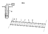
- a second embodiment of the method consists in using a tube 7, the part of which passes through the production area is provided with a plurality of openings 8 (FIG. 3) with selective opening.
- a tube provided with lateral openings which can be masked and unmasked at will by action on valves 9 such as valves with sliding sleeves as described in published patent application FR 2 626 614.
- valves 9 such as valves with sliding sleeves as described in published patent application FR 2 626 614.
- the openings 8 can be discovered either partially (valve 9A) or entirely (valve 9B).
- the selective opening of one of the valves has the effect of locally increasing the vacuum (Fig. 4) and of regulating the sweeping in the vicinity of the new opening.
- the first is the distance separating this location from the suction opening 6,8 and one can choose that of the lateral openings of the tube which is at the suitable distance.
- the second factor is the suction area and it can be modified by opening one or more of the valves 9 and / or by modifying the number of open valves.
- a production tube 10 is perforated over part of its length with a distribution of lateral perforations 11 along the tube.
- the density of perforations and / or their areas are chosen to obtain a distribution of depressions adapted to the configuration of the well.
Landscapes
- Geology (AREA)
- Life Sciences & Earth Sciences (AREA)
- Engineering & Computer Science (AREA)
- Mining & Mineral Resources (AREA)
- Environmental & Geological Engineering (AREA)
- Fluid Mechanics (AREA)
- Physics & Mathematics (AREA)
- General Life Sciences & Earth Sciences (AREA)
- Geochemistry & Mineralogy (AREA)
- Investigation Of Foundation Soil And Reinforcement Of Foundation Soil By Compacting Or Drainage (AREA)
- Fats And Perfumes (AREA)
- Structures Of Non-Positive Displacement Pumps (AREA)
- External Artificial Organs (AREA)
Applications Claiming Priority (2)
| Application Number | Priority Date | Filing Date | Title |
|---|---|---|---|
| FR9013691 | 1990-11-02 | ||
| FR9013691A FR2668795B1 (fr) | 1990-11-02 | 1990-11-02 | Methode pour favoriser la production d'effluents d'une zone de production. |
Publications (2)
| Publication Number | Publication Date |
|---|---|
| EP0484207A1 EP0484207A1 (fr) | 1992-05-06 |
| EP0484207B1 true EP0484207B1 (fr) | 1995-01-11 |
Family
ID=9401859
Family Applications (1)
| Application Number | Title | Priority Date | Filing Date |
|---|---|---|---|
| EP91402833A Expired - Lifetime EP0484207B1 (fr) | 1990-11-02 | 1991-10-23 | Méthode pour favoriser la production d'effluents d'une zone de production |
Country Status (8)
| Country | Link |
|---|---|
| US (1) | US5269376A (da) |
| EP (1) | EP0484207B1 (da) |
| AU (2) | AU8697091A (da) |
| BR (1) | BR9104767A (da) |
| CA (1) | CA2054780C (da) |
| DK (1) | DK0484207T3 (da) |
| FR (1) | FR2668795B1 (da) |
| NO (1) | NO302839B1 (da) |
Families Citing this family (11)
| Publication number | Priority date | Publication date | Assignee | Title |
|---|---|---|---|---|
| NO306127B1 (no) * | 1992-09-18 | 1999-09-20 | Norsk Hydro As | Fremgangsmate og produksjonsror for produksjon av olje eller gass fra et olje- eller gassreservoar |
| FR2741382B1 (fr) * | 1995-11-21 | 1997-12-26 | Inst Francais Du Petrole | Methode et dispositif de production par pompage dans un drain horizontal |
| NO314701B3 (no) * | 2001-03-20 | 2007-10-08 | Reslink As | Stromningsstyreanordning for struping av innstrommende fluider i en bronn |
| US6786285B2 (en) | 2001-06-12 | 2004-09-07 | Schlumberger Technology Corporation | Flow control regulation method and apparatus |
| US6857475B2 (en) | 2001-10-09 | 2005-02-22 | Schlumberger Technology Corporation | Apparatus and methods for flow control gravel pack |
| US7673678B2 (en) * | 2004-12-21 | 2010-03-09 | Schlumberger Technology Corporation | Flow control device with a permeable membrane |
| US7543641B2 (en) * | 2006-03-29 | 2009-06-09 | Schlumberger Technology Corporation | System and method for controlling wellbore pressure during gravel packing operations |
| US7857050B2 (en) * | 2006-05-26 | 2010-12-28 | Schlumberger Technology Corporation | Flow control using a tortuous path |
| US8025072B2 (en) * | 2006-12-21 | 2011-09-27 | Schlumberger Technology Corporation | Developing a flow control system for a well |
| US8196661B2 (en) | 2007-01-29 | 2012-06-12 | Noetic Technologies Inc. | Method for providing a preferential specific injection distribution from a horizontal injection well |
| US7789145B2 (en) * | 2007-06-20 | 2010-09-07 | Schlumberger Technology Corporation | Inflow control device |
Family Cites Families (10)
| Publication number | Priority date | Publication date | Assignee | Title |
|---|---|---|---|---|
| US3638731A (en) * | 1970-08-17 | 1972-02-01 | Amoco Prod Co | Multiple producing intervals to suppress coning |
| US4020901A (en) * | 1976-01-19 | 1977-05-03 | Chevron Research Company | Arrangement for recovering viscous petroleum from thick tar sand |
| US4460044A (en) * | 1982-08-31 | 1984-07-17 | Chevron Research Company | Advancing heated annulus steam drive |
| US4565245A (en) * | 1983-05-09 | 1986-01-21 | Texaco Inc. | Completion for tar sand substrate |
| US4640359A (en) * | 1985-11-12 | 1987-02-03 | Texaco Canada Resources Ltd. | Bitumen production through a horizontal well |
| US4714117A (en) * | 1987-04-20 | 1987-12-22 | Atlantic Richfield Company | Drainhole well completion |
| FR2631379A1 (fr) * | 1988-05-11 | 1989-11-17 | Inst Francais Du Petrole | Dispositif de pompage d'un fluide au fond d'un puits fore notamment a zone basse fortement inclinee ou horizontale |
| US4878539A (en) * | 1988-08-02 | 1989-11-07 | Anders Energy Corporation | Method and system for maintaining and producing horizontal well bores |
| EP0364362B1 (fr) * | 1988-10-14 | 1992-07-08 | Institut Français du Pétrole | Procédé et dispositif de diagraphie en puits de production non éruptif |
| US5111883A (en) * | 1990-05-24 | 1992-05-12 | Winsor Savery | Vacuum apparatus and process for in-situ removing underground liquids and vapors |
-
1990
- 1990-11-02 FR FR9013691A patent/FR2668795B1/fr not_active Expired - Fee Related
-
1991
- 1991-10-23 EP EP91402833A patent/EP0484207B1/fr not_active Expired - Lifetime
- 1991-10-23 DK DK91402833.7T patent/DK0484207T3/da active
- 1991-10-31 NO NO914279A patent/NO302839B1/no not_active IP Right Cessation
- 1991-11-01 BR BR919104767A patent/BR9104767A/pt not_active IP Right Cessation
- 1991-11-01 AU AU86970/91A patent/AU8697091A/en not_active Abandoned
- 1991-11-01 CA CA002054780A patent/CA2054780C/fr not_active Expired - Fee Related
- 1991-11-04 US US07/787,660 patent/US5269376A/en not_active Expired - Lifetime
-
1995
- 1995-04-13 AU AU16461/95A patent/AU687988B2/en not_active Ceased
Also Published As
| Publication number | Publication date |
|---|---|
| NO302839B1 (no) | 1998-04-27 |
| FR2668795A1 (fr) | 1992-05-07 |
| US5269376A (en) | 1993-12-14 |
| NO914279D0 (no) | 1991-10-31 |
| EP0484207A1 (fr) | 1992-05-06 |
| AU1646195A (en) | 1995-06-22 |
| AU8697091A (en) | 1992-05-07 |
| AU687988B2 (en) | 1998-03-05 |
| DK0484207T3 (da) | 1995-05-22 |
| NO914279L (no) | 1992-05-04 |
| CA2054780C (fr) | 2003-02-04 |
| CA2054780A1 (fr) | 1992-05-03 |
| FR2668795B1 (fr) | 1993-01-08 |
| BR9104767A (pt) | 1992-06-23 |
Similar Documents
| Publication | Publication Date | Title |
|---|---|---|
| EP0484207B1 (fr) | Méthode pour favoriser la production d'effluents d'une zone de production | |
| RU2196892C2 (ru) | Устройство и система (варианты) для увеличения добычи жидкости из подземных пластов | |
| EP1618281B1 (en) | Mandrel for a gas lift valve | |
| US20120006543A1 (en) | Downhole oil-water-solids separation | |
| US7814976B2 (en) | Flow control device and method for a downhole oil-water separator | |
| US5762149A (en) | Method and apparatus for well bore construction | |
| US7011157B2 (en) | Method and apparatus for cleaning a fractured interval between two packers | |
| EP0251881B1 (fr) | Méthode de production assistée d'un effluent à produire contenu dans une formation géologique | |
| AU2012299336B2 (en) | Systems and methods for gravel packing wells | |
| FR2656651A1 (fr) | Methode et dispositif pour stimuler une zone souterraine par injection differee de fluide provenant d'une zone voisine, le long de fractures faites depuis un drain fore dans une couche intermediaire peu permeable. | |
| GB2292574A (en) | Method for improving productivity of a well | |
| US6131660A (en) | Dual injection and lifting system using rod pump and an electric submersible pump (ESP) | |
| NZ527492A (en) | Gas lift valve with central body venturi for controlling the flow of injection gas in oil wells producing by continuous gas lift | |
| EP0435727B1 (fr) | Méthode et dispositif pour stimuler une zone souterraine par injection controlée de fluide provenant d'une zone voisine que l'on relie à la première par un drain traversant une couche intermédiaire peu perméable | |
| US20070012454A1 (en) | Flow Control Valve For Injection Systems | |
| RU2268999C2 (ru) | Скважина и способ добычи нефти из подземного пласта через скважину | |
| JP2004524467A (ja) | サンドトラップから沈殿物を除去する方法 | |
| US12473809B2 (en) | Downhole separator | |
| CA2850616A1 (en) | Screen assembly and methods of use | |
| US20200248537A1 (en) | Well production system | |
| EP1182355A1 (fr) | Dispositif pour drainer un sol en profondeur | |
| WO2001040624A3 (en) | Production valve | |
| RU2205940C2 (ru) | Способ эксплуатации нефтяных скважин, продуктивные пласты которых обводнены, и устройство для его осуществления | |
| SU1350336A1 (ru) | Устройство дл добычи углеводородов из обводн ющейс скважины | |
| SU1625947A1 (ru) | Способ строительства бескаркасных скважин комбинированного дренажа |
Legal Events
| Date | Code | Title | Description |
|---|---|---|---|
| PUAI | Public reference made under article 153(3) epc to a published international application that has entered the european phase |
Free format text: ORIGINAL CODE: 0009012 |
|
| 17P | Request for examination filed |
Effective date: 19911107 |
|
| AK | Designated contracting states |
Kind code of ref document: A1 Designated state(s): DK GB IT NL |
|
| 17Q | First examination report despatched |
Effective date: 19920907 |
|
| ITF | It: translation for a ep patent filed | ||
| GRAA | (expected) grant |
Free format text: ORIGINAL CODE: 0009210 |
|
| AK | Designated contracting states |
Kind code of ref document: B1 Designated state(s): DK GB IT NL |
|
| GBT | Gb: translation of ep patent filed (gb section 77(6)(a)/1977) |
Effective date: 19950120 |
|
| REG | Reference to a national code |
Ref country code: DK Ref legal event code: T3 |
|
| PLBE | No opposition filed within time limit |
Free format text: ORIGINAL CODE: 0009261 |
|
| STAA | Information on the status of an ep patent application or granted ep patent |
Free format text: STATUS: NO OPPOSITION FILED WITHIN TIME LIMIT |
|
| 26N | No opposition filed | ||
| REG | Reference to a national code |
Ref country code: GB Ref legal event code: IF02 |
|
| PGFP | Annual fee paid to national office [announced via postgrant information from national office to epo] |
Ref country code: NL Payment date: 20021031 Year of fee payment: 12 |
|
| PGFP | Annual fee paid to national office [announced via postgrant information from national office to epo] |
Ref country code: DK Payment date: 20031029 Year of fee payment: 13 |
|
| PG25 | Lapsed in a contracting state [announced via postgrant information from national office to epo] |
Ref country code: NL Free format text: LAPSE BECAUSE OF NON-PAYMENT OF DUE FEES Effective date: 20040501 |
|
| NLV4 | Nl: lapsed or anulled due to non-payment of the annual fee |
Effective date: 20040501 |
|
| PG25 | Lapsed in a contracting state [announced via postgrant information from national office to epo] |
Ref country code: DK Free format text: LAPSE BECAUSE OF NON-PAYMENT OF DUE FEES Effective date: 20041101 |
|
| REG | Reference to a national code |
Ref country code: DK Ref legal event code: EBP |
|
| PG25 | Lapsed in a contracting state [announced via postgrant information from national office to epo] |
Ref country code: IT Free format text: LAPSE BECAUSE OF NON-PAYMENT OF DUE FEES;WARNING: LAPSES OF ITALIAN PATENTS WITH EFFECTIVE DATE BEFORE 2007 MAY HAVE OCCURRED AT ANY TIME BEFORE 2007. THE CORRECT EFFECTIVE DATE MAY BE DIFFERENT FROM THE ONE RECORDED. Effective date: 20051023 |
|
| PGFP | Annual fee paid to national office [announced via postgrant information from national office to epo] |
Ref country code: GB Payment date: 20081028 Year of fee payment: 18 |
|
| PG25 | Lapsed in a contracting state [announced via postgrant information from national office to epo] |
Ref country code: GB Free format text: LAPSE BECAUSE OF NON-PAYMENT OF DUE FEES Effective date: 20091023 |