EP0484207A1 - Verfahren zum Befördern der Produktion einer Flüssigkeit in einer Produktionszone - Google Patents
Verfahren zum Befördern der Produktion einer Flüssigkeit in einer Produktionszone Download PDFInfo
- Publication number
- EP0484207A1 EP0484207A1 EP91402833A EP91402833A EP0484207A1 EP 0484207 A1 EP0484207 A1 EP 0484207A1 EP 91402833 A EP91402833 A EP 91402833A EP 91402833 A EP91402833 A EP 91402833A EP 0484207 A1 EP0484207 A1 EP 0484207A1
- Authority
- EP
- European Patent Office
- Prior art keywords
- tube
- production
- location
- openings
- depression
- Prior art date
- Legal status (The legal status is an assumption and is not a legal conclusion. Google has not performed a legal analysis and makes no representation as to the accuracy of the status listed.)
- Granted
Links
- 238000004519 manufacturing process Methods 0.000 title claims abstract description 32
- 238000000034 method Methods 0.000 title claims description 21
- 239000012530 fluid Substances 0.000 title abstract 2
- 238000005086 pumping Methods 0.000 claims abstract description 11
- 230000004048 modification Effects 0.000 claims abstract description 3
- 238000012986 modification Methods 0.000 claims abstract description 3
- 230000015572 biosynthetic process Effects 0.000 claims description 5
- 230000001737 promoting effect Effects 0.000 claims description 2
- 230000004913 activation Effects 0.000 abstract description 4
- 238000006073 displacement reaction Methods 0.000 abstract 1
- 230000000638 stimulation Effects 0.000 abstract 1
- 238000010408 sweeping Methods 0.000 description 6
- 238000005755 formation reaction Methods 0.000 description 4
- 230000001105 regulatory effect Effects 0.000 description 4
- 238000009825 accumulation Methods 0.000 description 3
- 230000007423 decrease Effects 0.000 description 2
- 230000000694 effects Effects 0.000 description 2
- 238000009434 installation Methods 0.000 description 2
- 238000011084 recovery Methods 0.000 description 2
- 230000009471 action Effects 0.000 description 1
- 230000033228 biological regulation Effects 0.000 description 1
- 230000007246 mechanism Effects 0.000 description 1
- 239000003208 petroleum Substances 0.000 description 1
- XLYOFNOQVPJJNP-UHFFFAOYSA-N water Substances O XLYOFNOQVPJJNP-UHFFFAOYSA-N 0.000 description 1
Images

Classifications
-
- E—FIXED CONSTRUCTIONS
- E21—EARTH OR ROCK DRILLING; MINING
- E21B—EARTH OR ROCK DRILLING; OBTAINING OIL, GAS, WATER, SOLUBLE OR MELTABLE MATERIALS OR A SLURRY OF MINERALS FROM WELLS
- E21B43/00—Methods or apparatus for obtaining oil, gas, water, soluble or meltable materials or a slurry of minerals from wells
- E21B43/12—Methods or apparatus for controlling the flow of the obtained fluid to or in wells
- E21B43/121—Lifting well fluids
-
- E—FIXED CONSTRUCTIONS
- E21—EARTH OR ROCK DRILLING; MINING
- E21B—EARTH OR ROCK DRILLING; OBTAINING OIL, GAS, WATER, SOLUBLE OR MELTABLE MATERIALS OR A SLURRY OF MINERALS FROM WELLS
- E21B43/00—Methods or apparatus for obtaining oil, gas, water, soluble or meltable materials or a slurry of minerals from wells
- E21B43/30—Specific pattern of wells, e.g. optimising the spacing of wells
- E21B43/305—Specific pattern of wells, e.g. optimising the spacing of wells comprising at least one inclined or horizontal well
Definitions
- the present invention relates to a method for promoting, by creating a depression, the production of effluents from a production zone crossed by at least one deviated well or drain, such as an oil zone.
- deviated well designates any well of which at least part is substantially horizontal or slightly inclined relative to the horizontal.
- One of the advantages of deviated wells is to allow better sweeping of the petroleum effluents contained in the formations crossed and therefore to improve recovery.
- Optimal recovery for a given scanning mechanism, is obtained when the scanning front moves parallel to the deviated drain.
- the regularity of the sweeping front is sometimes difficult to maintain due to heterogeneities of the reservoir, such as fractures or channels etc., changes in the geometry of the drain or even disturbances related to flows in the drain such as pressure drops .
- a known method for sweeping a production area is to lower a pumping device there to suck out the effluents when the pressure in the formation becomes insufficient.
- the deviated well which crosses it is equipped with a casing or casing tube which is perforated in its part which crosses the production zone.
- a production tube is lowered into the area to be activated.
- a pump is inserted on the tube to create a vacuum.
- An example of a pumping device is described for example in the French patent application EN. 08/08/270.
- the vacuum created by such a tube is maximum near its lower end and, due to the pressure drops, it decreases quickly with the distance so that the suction pressure quickly becomes insufficient to obtain a correct sweeping of the production area.
- the layer containing the oil is relatively thin. It is bordered on one side by an accumulation of gas or an aquifer. It can still be between an accumulation of gas and an aquifer. Too strong a vacuum at the outlet of the tube has the effect in this case, also to bring the gas or water from the adjacent layers.
- the method according to the invention makes it possible, by creating a depression, to promote the production of effluents by a production zone crossed by at least one deviated well or drain, into which a tube is lowered, the lower part of which is at least provided with openings.
- the extent of the depression is selectively varied in at least one location of the tube by a selective modification of the position of the openings where the depression is applied relative to said location and / or the area application openings of this depression.
- the method includes regulating the vacuum in at least one location of the well by adapting the pressure drop undergone by the effluents produced between this location and said openings.
- the appropriate pressure drop is obtained at said location, for example by using a tube provided with at least one opening for applying vacuum and by varying the length of the path between said location and an opening of the tube and / or the section of said opening.
- the tube can also be provided with a plurality of openings distributed over its length and means for varying the section of at least part of the openings, the method comprising in this case the selection of at least at least one of said openings the distance of which at said location and / or the section are chosen to obtain at said location a depression.
- the method may include the use of a perforated suction tube and / or a perforated casing, the distribution of the perforations and their areas being chosen to obtain a determined depression distribution.
- the method according to the invention may include the use of a suction means such as a pumping assembly, to increase the vacuum applied to the training.
- a suction means such as a pumping assembly
- the method relates to the scanning of a producing area by creating a depression in a formation 1 put into production.
- the formation is crossed (Fig. 2) by a deviated well or drain 2, the lower part of which is horizontal or at a slight inclination relative to the horizontal.
- the well is generally provided with a casing or casing tube perforated 3 in its part which crosses the production zone.
- a production tube 4 is lowered into the zone to be activated.
- a pump 5 is interposed on the tube so as to create a vacuum.
- An example of a pumping device is described for example in the French patent application EN. 02/02/270.
- the vacuum dp created is maximum near the lower end 6 of the tube 4 (Fig. 2) and, due to the pressure losses, it decreases with the distance d (Fig. 2), so that the pressure d Aspiration becomes insufficient to obtain a correct sweep of the production area.
- a first embodiment of the method consists in moving the lower end of the tube 4 opening into the production area, so that at any location of the drain, a sufficient vacuum is obtained to favor the arrival of oil with a good sweep of the area, without creating other unwanted inflows.
- play is made on the relative position of the locations of the drain relative to the suction opening.
- a second embodiment of the method consists in using a tube 7, the part of which passes through the production area is provided with a plurality of openings 8 (FIG. 3) with selective opening.
- a tube provided with lateral openings which can be masked and unmasked at will by action on valves 9 such as sliding jacket valves as described in published patent application FR 2 626 614.
- valves 9 such as sliding jacket valves as described in published patent application FR 2 626 614.
- the openings 8 can be discovered either partially (valve 9A) or entirely (valve 9B).
- the selective opening of one of the valves has the effect of locally increasing the vacuum (Fig. 4) and of regulating the sweeping in the vicinity of the new opening.
- the first is the distance separating this location from the suction opening 6,8 and one can choose that of the lateral openings of the tube which is at the suitable distance.
- the second factor is the suction area and it can be modified by opening one or more of the valves 9 and / or by modifying the number of open valves.
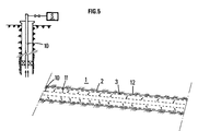
- a production tube 10 is perforated over a part of its length with a distribution of lateral perforations 11 along the tube.
- the density of perforations and / or their areas are chosen to obtain a distribution of depressions adapted to the configuration of the well.
Landscapes
- Geology (AREA)
- Life Sciences & Earth Sciences (AREA)
- Engineering & Computer Science (AREA)
- Mining & Mineral Resources (AREA)
- Environmental & Geological Engineering (AREA)
- Fluid Mechanics (AREA)
- Physics & Mathematics (AREA)
- General Life Sciences & Earth Sciences (AREA)
- Geochemistry & Mineralogy (AREA)
- Investigation Of Foundation Soil And Reinforcement Of Foundation Soil By Compacting Or Drainage (AREA)
- Fats And Perfumes (AREA)
- Structures Of Non-Positive Displacement Pumps (AREA)
- External Artificial Organs (AREA)
Applications Claiming Priority (2)
| Application Number | Priority Date | Filing Date | Title |
|---|---|---|---|
| FR9013691 | 1990-11-02 | ||
| FR9013691A FR2668795B1 (fr) | 1990-11-02 | 1990-11-02 | Methode pour favoriser la production d'effluents d'une zone de production. |
Publications (2)
| Publication Number | Publication Date |
|---|---|
| EP0484207A1 true EP0484207A1 (de) | 1992-05-06 |
| EP0484207B1 EP0484207B1 (de) | 1995-01-11 |
Family
ID=9401859
Family Applications (1)
| Application Number | Title | Priority Date | Filing Date |
|---|---|---|---|
| EP91402833A Expired - Lifetime EP0484207B1 (de) | 1990-11-02 | 1991-10-23 | Verfahren zum Befördern der Produktion einer Flüssigkeit in einer Produktionszone |
Country Status (8)
| Country | Link |
|---|---|
| US (1) | US5269376A (de) |
| EP (1) | EP0484207B1 (de) |
| AU (2) | AU8697091A (de) |
| BR (1) | BR9104767A (de) |
| CA (1) | CA2054780C (de) |
| DK (1) | DK0484207T3 (de) |
| FR (1) | FR2668795B1 (de) |
| NO (1) | NO302839B1 (de) |
Cited By (1)
| Publication number | Priority date | Publication date | Assignee | Title |
|---|---|---|---|---|
| FR2741382A1 (fr) * | 1995-11-21 | 1997-05-23 | Inst Francais Du Petrole | Methode et dispositif de production par pompage dans un drain horizontal |
Families Citing this family (10)
| Publication number | Priority date | Publication date | Assignee | Title |
|---|---|---|---|---|
| NO306127B1 (no) * | 1992-09-18 | 1999-09-20 | Norsk Hydro As | Fremgangsmate og produksjonsror for produksjon av olje eller gass fra et olje- eller gassreservoar |
| NO314701B3 (no) * | 2001-03-20 | 2007-10-08 | Reslink As | Stromningsstyreanordning for struping av innstrommende fluider i en bronn |
| US6786285B2 (en) | 2001-06-12 | 2004-09-07 | Schlumberger Technology Corporation | Flow control regulation method and apparatus |
| US6857475B2 (en) | 2001-10-09 | 2005-02-22 | Schlumberger Technology Corporation | Apparatus and methods for flow control gravel pack |
| US7673678B2 (en) * | 2004-12-21 | 2010-03-09 | Schlumberger Technology Corporation | Flow control device with a permeable membrane |
| US7543641B2 (en) * | 2006-03-29 | 2009-06-09 | Schlumberger Technology Corporation | System and method for controlling wellbore pressure during gravel packing operations |
| US7857050B2 (en) * | 2006-05-26 | 2010-12-28 | Schlumberger Technology Corporation | Flow control using a tortuous path |
| US8025072B2 (en) * | 2006-12-21 | 2011-09-27 | Schlumberger Technology Corporation | Developing a flow control system for a well |
| US8196661B2 (en) | 2007-01-29 | 2012-06-12 | Noetic Technologies Inc. | Method for providing a preferential specific injection distribution from a horizontal injection well |
| US7789145B2 (en) * | 2007-06-20 | 2010-09-07 | Schlumberger Technology Corporation | Inflow control device |
Citations (4)
| Publication number | Priority date | Publication date | Assignee | Title |
|---|---|---|---|---|
| US4565245A (en) * | 1983-05-09 | 1986-01-21 | Texaco Inc. | Completion for tar sand substrate |
| US4878539A (en) * | 1988-08-02 | 1989-11-07 | Anders Energy Corporation | Method and system for maintaining and producing horizontal well bores |
| FR2631379A1 (fr) * | 1988-05-11 | 1989-11-17 | Inst Francais Du Petrole | Dispositif de pompage d'un fluide au fond d'un puits fore notamment a zone basse fortement inclinee ou horizontale |
| EP0364362A1 (de) * | 1988-10-14 | 1990-04-18 | Institut Français du Pétrole | Verfahren und Vorrichtung zum Messen in einem nichteruptiven Bohrloch |
Family Cites Families (6)
| Publication number | Priority date | Publication date | Assignee | Title |
|---|---|---|---|---|
| US3638731A (en) * | 1970-08-17 | 1972-02-01 | Amoco Prod Co | Multiple producing intervals to suppress coning |
| US4020901A (en) * | 1976-01-19 | 1977-05-03 | Chevron Research Company | Arrangement for recovering viscous petroleum from thick tar sand |
| US4460044A (en) * | 1982-08-31 | 1984-07-17 | Chevron Research Company | Advancing heated annulus steam drive |
| US4640359A (en) * | 1985-11-12 | 1987-02-03 | Texaco Canada Resources Ltd. | Bitumen production through a horizontal well |
| US4714117A (en) * | 1987-04-20 | 1987-12-22 | Atlantic Richfield Company | Drainhole well completion |
| US5111883A (en) * | 1990-05-24 | 1992-05-12 | Winsor Savery | Vacuum apparatus and process for in-situ removing underground liquids and vapors |
-
1990
- 1990-11-02 FR FR9013691A patent/FR2668795B1/fr not_active Expired - Fee Related
-
1991
- 1991-10-23 EP EP91402833A patent/EP0484207B1/de not_active Expired - Lifetime
- 1991-10-23 DK DK91402833.7T patent/DK0484207T3/da active
- 1991-10-31 NO NO914279A patent/NO302839B1/no not_active IP Right Cessation
- 1991-11-01 BR BR919104767A patent/BR9104767A/pt not_active IP Right Cessation
- 1991-11-01 AU AU86970/91A patent/AU8697091A/en not_active Abandoned
- 1991-11-01 CA CA002054780A patent/CA2054780C/fr not_active Expired - Fee Related
- 1991-11-04 US US07/787,660 patent/US5269376A/en not_active Expired - Lifetime
-
1995
- 1995-04-13 AU AU16461/95A patent/AU687988B2/en not_active Ceased
Patent Citations (4)
| Publication number | Priority date | Publication date | Assignee | Title |
|---|---|---|---|---|
| US4565245A (en) * | 1983-05-09 | 1986-01-21 | Texaco Inc. | Completion for tar sand substrate |
| FR2631379A1 (fr) * | 1988-05-11 | 1989-11-17 | Inst Francais Du Petrole | Dispositif de pompage d'un fluide au fond d'un puits fore notamment a zone basse fortement inclinee ou horizontale |
| US4878539A (en) * | 1988-08-02 | 1989-11-07 | Anders Energy Corporation | Method and system for maintaining and producing horizontal well bores |
| EP0364362A1 (de) * | 1988-10-14 | 1990-04-18 | Institut Français du Pétrole | Verfahren und Vorrichtung zum Messen in einem nichteruptiven Bohrloch |
Cited By (2)
| Publication number | Priority date | Publication date | Assignee | Title |
|---|---|---|---|---|
| FR2741382A1 (fr) * | 1995-11-21 | 1997-05-23 | Inst Francais Du Petrole | Methode et dispositif de production par pompage dans un drain horizontal |
| US5829529A (en) * | 1995-11-21 | 1998-11-03 | Institut Francais De Petrole | Method and device for producing by pumping in a horizontal drain hole |
Also Published As
| Publication number | Publication date |
|---|---|
| NO302839B1 (no) | 1998-04-27 |
| FR2668795A1 (fr) | 1992-05-07 |
| US5269376A (en) | 1993-12-14 |
| NO914279D0 (no) | 1991-10-31 |
| EP0484207B1 (de) | 1995-01-11 |
| AU1646195A (en) | 1995-06-22 |
| AU8697091A (en) | 1992-05-07 |
| AU687988B2 (en) | 1998-03-05 |
| DK0484207T3 (da) | 1995-05-22 |
| NO914279L (no) | 1992-05-04 |
| CA2054780C (fr) | 2003-02-04 |
| CA2054780A1 (fr) | 1992-05-03 |
| FR2668795B1 (fr) | 1993-01-08 |
| BR9104767A (pt) | 1992-06-23 |
Similar Documents
| Publication | Publication Date | Title |
|---|---|---|
| CA2033358C (fr) | Methode et dispositif pour stimuler une zone souterraine par injection differee de fluide provenant d'une zone voisine, le long de fractures faites depuis un drain fore dans une couche intermediaire peu permeable | |
| EP0251881B1 (de) | Gewinnungsverfahren für eine in einer geologischen Formation enthaltene zu produzierende Flüssigkeit | |
| RU2531984C2 (ru) | Разделение нефти, воды и твердых частиц внутри скважины | |
| RU2196892C2 (ru) | Устройство и система (варианты) для увеличения добычи жидкости из подземных пластов | |
| CA2204664C (fr) | Systeme de pompage polyphasique et centrifuge | |
| US7814976B2 (en) | Flow control device and method for a downhole oil-water separator | |
| GB2292574A (en) | Method for improving productivity of a well | |
| EP0435727B1 (de) | Verfahren und Vorrichtung zur Stimulation einer Untergrundformation durch Injektion eines Fluids aus einer benachbarten Schicht, die durch eine eine niedrigpermeable Zwischenschicht durchquerende Bohrung mit ersterer verbunden ist | |
| EP0484207A1 (de) | Verfahren zum Befördern der Produktion einer Flüssigkeit in einer Produktionszone | |
| US20030141073A1 (en) | Advanced gas injection method and apparatus liquid hydrocarbon recovery complex | |
| NZ527492A (en) | Gas lift valve with central body venturi for controlling the flow of injection gas in oil wells producing by continuous gas lift | |
| US8080157B2 (en) | Downhole gravitational water separator | |
| MXPA05008753A (es) | Aparato y metodo de control de presion anular dinamico. | |
| WO2005042909A3 (en) | Well screen primary tube gravel pack method | |
| NO335049B1 (no) | Spindel for en gassløfteventil | |
| EP0532397A1 (de) | Kontinuierliche Mischvorrichtung, Verfahren und Verwendung in einer Pumpanlage für Fluid hoher Viskosität | |
| EA025327B1 (ru) | Настраиваемое устройство регулирования потока для использования при добыче углеводородов | |
| US20070012454A1 (en) | Flow Control Valve For Injection Systems | |
| CA2480237C (fr) | Methode et systeme de pompage dans un puits petrolier | |
| NO331758B1 (no) | Anordning og fremgangsmate for behandling og gruspakking av soner beliggende i naerheten av hverandre | |
| CA3188611A1 (en) | Downhole separator | |
| US20200248537A1 (en) | Well production system | |
| FR2668796A1 (fr) | Methode pour favoriser l'injection de fluides dans une zone de production. | |
| EP1182355A1 (de) | Einrichtung zur Tiefbodendrainage | |
| RU2205940C2 (ru) | Способ эксплуатации нефтяных скважин, продуктивные пласты которых обводнены, и устройство для его осуществления |
Legal Events
| Date | Code | Title | Description |
|---|---|---|---|
| PUAI | Public reference made under article 153(3) epc to a published international application that has entered the european phase |
Free format text: ORIGINAL CODE: 0009012 |
|
| 17P | Request for examination filed |
Effective date: 19911107 |
|
| AK | Designated contracting states |
Kind code of ref document: A1 Designated state(s): DK GB IT NL |
|
| 17Q | First examination report despatched |
Effective date: 19920907 |
|
| ITF | It: translation for a ep patent filed | ||
| GRAA | (expected) grant |
Free format text: ORIGINAL CODE: 0009210 |
|
| AK | Designated contracting states |
Kind code of ref document: B1 Designated state(s): DK GB IT NL |
|
| GBT | Gb: translation of ep patent filed (gb section 77(6)(a)/1977) |
Effective date: 19950120 |
|
| REG | Reference to a national code |
Ref country code: DK Ref legal event code: T3 |
|
| PLBE | No opposition filed within time limit |
Free format text: ORIGINAL CODE: 0009261 |
|
| STAA | Information on the status of an ep patent application or granted ep patent |
Free format text: STATUS: NO OPPOSITION FILED WITHIN TIME LIMIT |
|
| 26N | No opposition filed | ||
| REG | Reference to a national code |
Ref country code: GB Ref legal event code: IF02 |
|
| PGFP | Annual fee paid to national office [announced via postgrant information from national office to epo] |
Ref country code: NL Payment date: 20021031 Year of fee payment: 12 |
|
| PGFP | Annual fee paid to national office [announced via postgrant information from national office to epo] |
Ref country code: DK Payment date: 20031029 Year of fee payment: 13 |
|
| PG25 | Lapsed in a contracting state [announced via postgrant information from national office to epo] |
Ref country code: NL Free format text: LAPSE BECAUSE OF NON-PAYMENT OF DUE FEES Effective date: 20040501 |
|
| NLV4 | Nl: lapsed or anulled due to non-payment of the annual fee |
Effective date: 20040501 |
|
| PG25 | Lapsed in a contracting state [announced via postgrant information from national office to epo] |
Ref country code: DK Free format text: LAPSE BECAUSE OF NON-PAYMENT OF DUE FEES Effective date: 20041101 |
|
| REG | Reference to a national code |
Ref country code: DK Ref legal event code: EBP |
|
| PG25 | Lapsed in a contracting state [announced via postgrant information from national office to epo] |
Ref country code: IT Free format text: LAPSE BECAUSE OF NON-PAYMENT OF DUE FEES;WARNING: LAPSES OF ITALIAN PATENTS WITH EFFECTIVE DATE BEFORE 2007 MAY HAVE OCCURRED AT ANY TIME BEFORE 2007. THE CORRECT EFFECTIVE DATE MAY BE DIFFERENT FROM THE ONE RECORDED. Effective date: 20051023 |
|
| PGFP | Annual fee paid to national office [announced via postgrant information from national office to epo] |
Ref country code: GB Payment date: 20081028 Year of fee payment: 18 |
|
| PG25 | Lapsed in a contracting state [announced via postgrant information from national office to epo] |
Ref country code: GB Free format text: LAPSE BECAUSE OF NON-PAYMENT OF DUE FEES Effective date: 20091023 |