EP0484111B1 - Kreiselverdichter mit rohrförmigem Diffusor und Kollektor - Google Patents
Kreiselverdichter mit rohrförmigem Diffusor und Kollektor Download PDFInfo
- Publication number
- EP0484111B1 EP0484111B1 EP91309993A EP91309993A EP0484111B1 EP 0484111 B1 EP0484111 B1 EP 0484111B1 EP 91309993 A EP91309993 A EP 91309993A EP 91309993 A EP91309993 A EP 91309993A EP 0484111 B1 EP0484111 B1 EP 0484111B1
- Authority
- EP
- European Patent Office
- Prior art keywords
- diffuser
- refrigerant
- section
- set forth
- channels
- Prior art date
- Legal status (The legal status is an assumption and is not a legal conclusion. Google has not performed a legal analysis and makes no representation as to the accuracy of the status listed.)
- Expired - Lifetime
Links
- 239000003507 refrigerant Substances 0.000 claims description 27
- 238000009792 diffusion process Methods 0.000 claims description 15
- VOPWNXZWBYDODV-UHFFFAOYSA-N Chlorodifluoromethane Chemical group FC(F)Cl VOPWNXZWBYDODV-UHFFFAOYSA-N 0.000 claims description 2
- 239000007789 gas Substances 0.000 description 10
- 230000006835 compression Effects 0.000 description 3
- 238000007906 compression Methods 0.000 description 3
- CYRMSUTZVYGINF-UHFFFAOYSA-N trichlorofluoromethane Chemical compound FC(Cl)(Cl)Cl CYRMSUTZVYGINF-UHFFFAOYSA-N 0.000 description 3
- 230000005540 biological transmission Effects 0.000 description 2
- 238000006243 chemical reaction Methods 0.000 description 2
- 238000004378 air conditioning Methods 0.000 description 1
- 238000005266 casting Methods 0.000 description 1
- 238000010276 construction Methods 0.000 description 1
- 230000000694 effects Effects 0.000 description 1
- 238000009434 installation Methods 0.000 description 1
- 238000003754 machining Methods 0.000 description 1
- 238000012986 modification Methods 0.000 description 1
- 230000004048 modification Effects 0.000 description 1
- 238000011144 upstream manufacturing Methods 0.000 description 1
Images


Classifications
-
- F—MECHANICAL ENGINEERING; LIGHTING; HEATING; WEAPONS; BLASTING
- F04—POSITIVE - DISPLACEMENT MACHINES FOR LIQUIDS; PUMPS FOR LIQUIDS OR ELASTIC FLUIDS
- F04D—NON-POSITIVE-DISPLACEMENT PUMPS
- F04D29/00—Details, component parts, or accessories
- F04D29/40—Casings; Connections of working fluid
- F04D29/42—Casings; Connections of working fluid for radial or helico-centrifugal pumps
- F04D29/44—Fluid-guiding means, e.g. diffusers
- F04D29/441—Fluid-guiding means, e.g. diffusers especially adapted for elastic fluid pumps
- F04D29/444—Bladed diffusers
-
- F—MECHANICAL ENGINEERING; LIGHTING; HEATING; WEAPONS; BLASTING
- F05—INDEXING SCHEMES RELATING TO ENGINES OR PUMPS IN VARIOUS SUBCLASSES OF CLASSES F01-F04
- F05D—INDEXING SCHEME FOR ASPECTS RELATING TO NON-POSITIVE-DISPLACEMENT MACHINES OR ENGINES, GAS-TURBINES OR JET-PROPULSION PLANTS
- F05D2250/00—Geometry
- F05D2250/50—Inlet or outlet
- F05D2250/52—Outlet
Definitions
- This invention relates generally to refrigerating systems which include refrigerant compressors and, more particularly, which include centrifugal compressors with a unique diffuser and collector combination for obtaining high efficiency performance.
- centrifugal compressors In large capacity air conditioning systems using water-cooled chillers, centrifugal compressors are most commonly used.
- the refrigerant of choice in such compressors has commonly been CFC-11, which is relatively high in thermodynamic cycle efficiency.
- the size of the various components can be determined. If the speed is considered to be fixed, as is generally the case, then the impeller diameter and width are chosen to fit the particular capacity requirements. It is, of course, the impeller which accelerates the refrigerant to a high velocity, after which it is necessary to decelerate the refrigerant to a low velocity while converting kinetic energy to pressure energy. This is commonly done with the diffuser and, to some extent, with the chamber into which the diffuser discharges its refrigerant.
- CFC-11 as the refrigerant
- complete diffusion i.e. the conversion of substantially all of the kinetic energy to pressure energy
- the normal approach is to complete the diffusion process in a spiral shaped casing called a volute.
- the volute therefore functions to both complete the diffusion process and to collect the discharge vapor for subsequent flow to the condenser. While the volute with its gradually increasing cross section provides an optimum design for the use of available space, it is recognized that some efficiency is lost in the diffusion that takes place in the volute.
- a compressor having an impeller, diffuser and volute is described in, for example, EP-A-0198784.
- centrifugal compressors have a volute with an outside diameter which is about twice the impeller diameter. Under these geometrical conditions, the amount of diffusion in the compressor is therefore limited. To obtain further diffusion, it would not only require a larger diffuser outside diameter, and therefore a larger volute diameter, but it would also require a larger cross sectional area in the volute in order to enable the passing of a given volumetric flow rate at lower velocities. Because of these constraints, centrifugal compressors with conventional, size-limited diffuser/volute combinations experience increased circumferential flow distortions under part load conditions when the volute becomes oversized and starts acting as a circumferential diffuser.
- CH-A-306143 discloses a multistage centrifugal compressor in which diffuser elements in respective stages have exit to entrance area ratios of 4.77, 4.75, and 4.71.
- the diffuser comprises a pipe or channel diffuser having a plurality of circumferentially spaced, outwardly extending, frustro-conical channels whose lengths are chosen such that they provide a 5:1 area ratio to thereby allow for substantially complete diffusion of the refrigerant gases.
- the conventional volute of a centrifugal compressor is replaced with a circumferentially symmetrical collector for receiving the low velocity gas from the diffuser. Because of the substantially complete diffusion that occurs in the diffuser, the circumferential pressure distortion that occurs in the collector due to nonuniform velocities will be minimal. Further, because of the relatively larger cross sectional area of the collector, as compared with that of a volute, the relatively larger flow volumes resulting from the more complete diffusion of the refrigerant gases can be accommodated without restriction. In this way, a channel diffuser, wherein substantially complete diffusion takes place, and a relatively large collector with a uniform circumferential cross section, are used effectively in combination to bring about optimum efficiency over a large stable operating range, and all within the given geometric constraints.
- a relatively high density refrigerant gas (e.g. HCFC-22) is used such that, when applying conventional scaling laws, the linear size of the aerodynamic components may be reduced to such an extent that the motor and drive apparatus becomes the size determining elements rather than the aerodynamic structure, with the reduced size then allowing provision for obtaining complete conversion of kinetic energy to pressure energy within the diffuser, so as to thereby provide for higher efficiencies. In this way, the efficiency of the diffusion process is optimized while remaining within the geometric constraints.
- the refrigerant gas is preferably of a higher density than CFC-11.
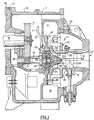
- Figure 1 is a partial sectional view of a centrifugal compressor for a refrigerating system in accordance with the present invention.
- Figure 2 is a partial end view of the impeller portion of the invention.
- Figure 3 is a sectional view as seen along lines 3-3 thereof.
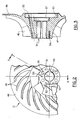
- Figure 4 is an axial sectional view of the diffuser portion of the invention.
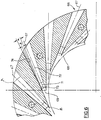
- Figure 5 is a sectional view as seen along lines 5-5 thereof.
- Figure 6 is a partial enlarged view thereof.
- Figure 7 is a sectional view of the collecter portion of the invention.
- Figure 8 is a sectional view as seen along lines 8-8 thereof.
- the invention is shown generally at 10 as installed in a centrifugal compressor 11 having an impeller 12 for accelerating refrigerant vapor to a high velocity, a diffuser 13 for decelerating the refrigerant to a low velocity while converting kinetic energy to pressure energy, and a discharge plenum in the form of a collector 14 to collect the discharge vapor for subsequent flow to a condenser.
- Power to the impeller 12 is provided by an electric motor (not shown) which is hermetically sealed in the other end of the compressor and which operates to rotate the low speed shaft 16 which, in turn, is drivingly connected to a drive gear 17, a driven gear 18, and a high speed shaft 19.
- the high speed shaft 19 is supported by the bearings 21 and 22 on either end thereof, with the bearing 22 acting as both a journal bearing to maintain the radial position of the shaft 19 and as a thrust bearing to maintain the axial position thereof.
- a balance piston is provided by way of a low pressure cavity 20 behind the impeller wheel 12.
- a plurality of passages 25 are provided in the impeller 12 in order to maintain the pressure in the cavity or balance piston 20 at the same low pressure as that in the compressor suction area indicated generally by the numeral 23.
- a labyrinth seal 26 is provided between the bearing 22 and the impeller 12 to seal that area against the flow of oil and gas from the transmission into the balance piston 20. This concept is well known, as is the further concept of pressurizing the labyrinth seal by exerting high pressure gas thereon.
- the high pressure vapor for pressurizing the labyrinth seal is introduced by way of the line 27 and its associated passages indicated at 28.
- the refrigerant enters the inlet opening 29 of the suction housing 31, passes through the blade ring assembly 32 and the guidevanes 33, and then enters the compression suction area 23 which leads to the compression area defined on its inner side by the impeller 12 and on its outer side by the shroud 34. After compression, the refrigerant then flows into the diffuser 13, the collecter 14 and the discharge line (not shown).
- the compressor base 36 which has the collector 14 as an integral part thereof, is attached to the transmission case 37 and to the motor housing 38 by appropriate fasteners such as bolts (not shown) or the like.
- the suction housing 31 is attached to the compressor base 36 by a plurality of bolts 39.
- the blade ring assembly 32 is then secured to the inner end 41 of the suction housing 31 by bolts 45.
- the diffuser 13 Prior to installing the suction housing 31 to the compressor base 36, the diffuser 13 is attached to an annular face 42 of the compressor base 36 by a plurality of bolts 43 as shown.
- the shroud 34 is then secured to the diffuser structure by a plurality of bolts 44.
- a small gap 46 is then allowed to remain between the intake end 47 of the shroud 34 and the downstream side of the blade ring assembly 32.
- the impeller wheel 12 is shown in greater detail to include hub 50, the integrally connected and radially extending disk 48, and a plurality of blades 49.
- hub 50 Formed in the hub 50 is a hub bore 51 and key ways 52 and 53 for drivingly installing the impeller wheel 12 on the high speed shaft 19.
- the plurality of passages 25 for establishing the proper pressures for the balance piston 20 as discussed hereinabove, and a plurality of tapped holes 54 for securing the nose cone 56 to the impeller wheel as shown in Figure 1.
- the impeller wheel is designed to operate at a pressure ratio of at least 2 to 1.
- the shallow cylindrical cavity 20 which communicates with a low pressure area by way of the passages 25 in order to function as a balance piston as described hereinabove.
- an annular cavity 57 is formed nearer to the bore 51 for purposes of stress relief of the keyway passages 52 and for purposes of shimming to set the axial position of the impeller 12.
- the diffuser 13 is shown in greater detail in Figures 4-6. It is formed of a single annular casting and includes a body or ring portion 58, an inner annular flange 59, and an outer annular flange 61.
- the inner annular flange 59 serves to support the shroud structure 34 which is attached thereto by a plurality of bolts 44 as discussed above.
- the outer annular flange 61 has a radially extending rim 62 which engages an inner surface of the collecter 14 as shown in Figure 1.
- a groove 63 is formed in the end of the rim 62 to contain an annular seal (not shown) for preventing leakage of refrigerant from between the rim 62 and the edge of the collecter 14.
- a plurality of holes 64 for receiving the bolts 43 which secure the diffuser 13 to the collecter structure 14 as shown in Figure 1.
- each of the tapered channels 66 has three serially connected sections, all concentric with the axis 67, as indicated at 69, 71 and 72.
- First section 69 is cylindrical in form, (i.e., with a constant diameter) and is angled in such a manner that it crosses similar sections on either circumferential side thereof.
- a second section indicated at 71 has a slightly flared axial profile with the walls 73 being angled outwardly at an angle ⁇ with the walls of the section 69 or the axis 67.
- An angle that has been found to be suitable for ⁇ is 2°.
- the third section 72 has an axial profile which is flared even more with the walls 74 being angled at an angle ⁇ with the walls of the section 69 or the center line 67.
- An angle which has been found suitable for the angle ⁇ is 4°.
- the area ratio be on the order of 5 to 1 or greater. With such an established area ratio in the diffuser, the refrigerant gas leaving the diffuser will then be fully expanded so as to require a substantially large discharge area in which to be collected for further distribution downstream.
- the relatively large collecter apparatus 14 is therefore provided for that purpose.
- a radially extending wall 76 with its opening 77 provides the supporting structure for the impeller wheel 12, its drive shaft 19 and its bearing 22.
- its surface 42 is used to support the diffuser 13 which is secured thereto, and, as it extends even further radially outwardly, the toroidal shaped collecter 14 is formed as shown with a circumferential cross section that is relatively large and uniform in shape.
- the structure terminates at the radially inward end 78 which is adapted to interface with the groove 63 of the rim 62 of the diffuser 13 as described above.
- the plenum of the collector structure 14 should have a radial cross sectional area which is equal to or greater than one and a half, and preferably two, times the combined radial cross sectional areas of the diffuser channels 66 at their exit ends. Again, this exit end area is taken at a point that is normal to the channel axis at the location identified at A in Figure 6.
- the present invention has been disclosed with particular reference to a preferred embodiment, the concepts of this invention are readily adaptable to other embodiments, and those skilled in the art may vary the structure thereof without departing from the invention.
- the diffuser 13 has been described in terms of a so called pipe diffuser structure, other types of channeled diffusers such as a wedge type diffuser can be used in combination with the collecter structure in order to obtain the present invention.
Landscapes
- Engineering & Computer Science (AREA)
- Mechanical Engineering (AREA)
- General Engineering & Computer Science (AREA)
- Structures Of Non-Positive Displacement Pumps (AREA)
Claims (8)
- Kühlsystem mit einem Kreiselverdichter (11) und einem Kühlmittelgas, wobei der Verdichter (11) ein Laufrad (12) zur Beschleunigung des Kühlmittelgases auf eine hohe Geschwindigkeit, einen Diffusor (13) zur Umwandlung der kinetischen Energie des Gases in Druckenergie und eine Auslaßkammer zur Aufnahme des verzögerten Gases aus dem Diffusor zum Weitertransport zu einem Kondensor aufweist,
dadurch gekennzeichnet, daß:das System so ausgebildet ist, daß es eine im wesentlichen vollständige Diffusion des Kühlmittelgases im Diffusor durch Verwendung eines Kühlmittelgases relativ hoher Dichte und eines Diffusors bewirkt, der mehrere in Umfangsrichtung beabstandete, nach außen verlaufende, sich erweiternde Kanäle (66) aufweist, die Eintritts-Austrittsflächenverhältnisse von wenigstens 5:1 haben, und daßdie Auslaßkammer (14) einen im wesentlichen in Umfangsrichtung symmetrischen Kollektor (14) aufweist. - System nach Anspruch 1,
dadurch gekennzeichnet, daß
der Kollektor eine radiale Querschnittsfläche hat, die ausreichend groß ist, um das diffundierte Kühlmittel aus dem Diffusor ohne wesentliche Drosselung des Kühlmittelstromes im Diffusor (13) aufnehmen zu können. - System nach Anspruch 3,
dadurch gekennzeichnet, daß
die radiale Querschnittsfläche des Kollektors wenigstens 1,5 mal so groß wie die kombinierten Querschnittsflächen der Auslässe der Kanäle (66) ist. - System nach einem der vorhergehenden Ansprüche,
dadurch gekennzeichnet, daß
die Kanäle (66) jeweils zwei in Reihe liegende Abschnitte aufweisen, wobei der erste Abschnitt (21) divergierende Wände hat, die unter einem Winkel (2β) geneigt sind, und der zweite Abschnitt (22) divergierende Wände hat, die unter einem größeren zweiten Winkel (2α) geneigt sind. - System nach Anspruch 4,
dadurch gekennzeichnet, daß
der Winkel (2β) zwischen den Wänden im ersten Abschnitt (71) 4° und der Winkel zwischen den Wänden im zweiten Abschnitt 8° (2α) beträgt. - System nach einem der vorhergehenden Ansprüche,
dadurch gekennzeichnet, daß
die Kanäle (66) im Querschnitt rund sind. - System nach einem der vorhergehenden Ansprüche,
dadurch gekennzeichnet, daß
die Kanäle (66) im Längsschnitt kegelstumpfförmig sind. - Kreiselverdichter nach einem der vorhergehenden Ansprüche,
dadurch gekennzeichnet, daß
das Kühlmittel HCFC-22 ist.
Applications Claiming Priority (2)
| Application Number | Priority Date | Filing Date | Title |
|---|---|---|---|
| US60562090A | 1990-10-30 | 1990-10-30 | |
| US605620 | 1990-10-30 |
Publications (2)
| Publication Number | Publication Date |
|---|---|
| EP0484111A1 EP0484111A1 (de) | 1992-05-06 |
| EP0484111B1 true EP0484111B1 (de) | 1996-01-03 |
Family
ID=24424476
Family Applications (1)
| Application Number | Title | Priority Date | Filing Date |
|---|---|---|---|
| EP91309993A Expired - Lifetime EP0484111B1 (de) | 1990-10-30 | 1991-10-30 | Kreiselverdichter mit rohrförmigem Diffusor und Kollektor |
Country Status (7)
| Country | Link |
|---|---|
| US (1) | US5445496A (de) |
| EP (1) | EP0484111B1 (de) |
| JP (1) | JP2746783B2 (de) |
| KR (1) | KR950009062B1 (de) |
| CN (1) | CN1022854C (de) |
| AU (1) | AU648833B2 (de) |
| DE (1) | DE69116091T2 (de) |
Families Citing this family (36)
| Publication number | Priority date | Publication date | Assignee | Title |
|---|---|---|---|---|
| US5520507A (en) * | 1994-05-06 | 1996-05-28 | Ingersoll-Rand Company | Method and apparatus to achieve passive damping of flow disturbances in a centrifugal compressor to control compressor surge |
| JPH0893694A (ja) * | 1994-09-27 | 1996-04-09 | Kawasaki Heavy Ind Ltd | 遠心圧縮機用ディフューザおよびその製造方法 |
| US5669756A (en) * | 1996-06-07 | 1997-09-23 | Carrier Corporation | Recirculating diffuser |
| US5678412A (en) * | 1996-07-23 | 1997-10-21 | Integral Sciences Incorporated | Method for changing lubricant types in refrigeration or air conditioning machinery using lubricant overcharge |
| US7334990B2 (en) * | 2002-01-29 | 2008-02-26 | Ramgen Power Systems, Inc. | Supersonic compressor |
| US20030210980A1 (en) * | 2002-01-29 | 2003-11-13 | Ramgen Power Systems, Inc. | Supersonic compressor |
| KR100468081B1 (ko) * | 2002-03-21 | 2005-01-26 | 강정호 | 한약 엑기스 발효주 및 그 제조방법 |
| KR20030084143A (ko) * | 2002-04-25 | 2003-11-01 | 이길호 | 주류 제조방법 |
| US7293955B2 (en) * | 2002-09-26 | 2007-11-13 | Ramgen Power Systrms, Inc. | Supersonic gas compressor |
| US7434400B2 (en) * | 2002-09-26 | 2008-10-14 | Lawlor Shawn P | Gas turbine power plant with supersonic shock compression ramps |
| US7281379B2 (en) * | 2002-11-13 | 2007-10-16 | Utc Power Corporation | Dual-use radial turbomachine |
| US7174716B2 (en) | 2002-11-13 | 2007-02-13 | Utc Power Llc | Organic rankine cycle waste heat applications |
| US7146813B2 (en) * | 2002-11-13 | 2006-12-12 | Utc Power, Llc | Power generation with a centrifugal compressor |
| US6892522B2 (en) | 2002-11-13 | 2005-05-17 | Carrier Corporation | Combined rankine and vapor compression cycles |
| US6880344B2 (en) * | 2002-11-13 | 2005-04-19 | Utc Power, Llc | Combined rankine and vapor compression cycles |
| US7254949B2 (en) * | 2002-11-13 | 2007-08-14 | Utc Power Corporation | Turbine with vaned nozzles |
| US6962056B2 (en) * | 2002-11-13 | 2005-11-08 | Carrier Corporation | Combined rankine and vapor compression cycles |
| US7101151B2 (en) | 2003-09-24 | 2006-09-05 | General Electric Company | Diffuser for centrifugal compressor |
| US7374396B2 (en) * | 2005-02-28 | 2008-05-20 | General Electric Company | Bolt-on radial bleed manifold |
| RU2327060C1 (ru) * | 2006-11-23 | 2008-06-20 | Федеральное государственное унитарное предприятие "Центральный институт авиационного моторостроения имени П.И. Баранова" | Центробежный компрессор |
| US7905703B2 (en) * | 2007-05-17 | 2011-03-15 | General Electric Company | Centrifugal compressor return passages using splitter vanes |
| US7856834B2 (en) * | 2008-02-20 | 2010-12-28 | Trane International Inc. | Centrifugal compressor assembly and method |
| US9353765B2 (en) | 2008-02-20 | 2016-05-31 | Trane International Inc. | Centrifugal compressor assembly and method |
| US7975506B2 (en) | 2008-02-20 | 2011-07-12 | Trane International, Inc. | Coaxial economizer assembly and method |
| US8037713B2 (en) | 2008-02-20 | 2011-10-18 | Trane International, Inc. | Centrifugal compressor assembly and method |
| RU2445516C1 (ru) * | 2010-10-01 | 2012-03-20 | Закрытое акционерное общество "Научно-исследовательский и конструкторский институт центробежных и роторных компрессоров им. В.Б. Шнеппа" | Рабочее колесо центробежного компрессора (варианты) |
| US8851835B2 (en) * | 2010-12-21 | 2014-10-07 | Hamilton Sundstrand Corporation | Air cycle machine compressor diffuser |
| CN103562561A (zh) | 2011-06-01 | 2014-02-05 | 开利公司 | 经济化离心压缩机 |
| EP3077680A1 (de) * | 2013-12-05 | 2016-10-12 | General Electric Company | Kreiselverdichter mit gekrümmtem diffusionsdurchgangsteil |
| EP2980413A1 (de) * | 2014-07-29 | 2016-02-03 | L'air Liquide, Societe Anonyme Pour L'etude Et L'exploitation Des Procedes Georges Claude | Zentrifugaler Getriebeverdichter und Verfahren zum Zusammenbau eines zentrifugalen Getriebeverdichters |
| US10006341B2 (en) * | 2015-03-09 | 2018-06-26 | Caterpillar Inc. | Compressor assembly having a diffuser ring with tabs |
| US10352237B2 (en) | 2016-05-26 | 2019-07-16 | Rolls-Royce Corporation | Diffuser having shaped vanes |
| WO2020231897A1 (en) * | 2019-05-10 | 2020-11-19 | Carrier Corporation | Compressor with thrust control |
| CN113144803B (zh) * | 2021-04-15 | 2022-09-27 | 鑫磊压缩机股份有限公司 | 一种周向离心的油气分离筒 |
| WO2024035894A1 (en) | 2022-08-11 | 2024-02-15 | Next Gen Compression Llc | Method for efficient part load compressor operation |
| US12066027B2 (en) | 2022-08-11 | 2024-08-20 | Next Gen Compression Llc | Variable geometry supersonic compressor |
Family Cites Families (19)
| Publication number | Priority date | Publication date | Assignee | Title |
|---|---|---|---|---|
| US2114285A (en) * | 1936-11-28 | 1938-04-19 | Adolph L Berger | Diffuser for centrifugal compressors |
| US2157002A (en) * | 1938-05-07 | 1939-05-02 | Gen Electric | Diffuser for centrifugal compressors |
| US2708883A (en) * | 1950-03-03 | 1955-05-24 | Escher Wyss Ag | Arrangement for use in radial centrifugal compressors and pumps for the conversion of kinetic energy of the flowing medium into pressure energy |
| CH306143A (de) * | 1952-09-04 | 1955-03-31 | Oerlikon Maschf | Mehrstufiger Fliehkraftverdichter. |
| CH329149A (de) * | 1954-06-12 | 1958-04-15 | Buechi Alfred Dr Ing H C | Leitvorrichtung für Zentrifugalgebläse oder -pumpen |
| US2977042A (en) * | 1957-12-13 | 1961-03-28 | Sulzer Ag | One-stage radial compressor |
| US3150823A (en) * | 1962-02-12 | 1964-09-29 | Ass Elect Ind | Diffusers |
| CH417340A (de) * | 1964-07-14 | 1966-07-15 | Emile Egger & Cie S A | Mehrzweck-Pumpenaggregat |
| US3489340A (en) * | 1968-04-16 | 1970-01-13 | Garrett Corp | Centrifugal compressor |
| US3604818A (en) * | 1969-12-10 | 1971-09-14 | Avco Corp | Centrifugal compressor diffuser |
| US4012166A (en) * | 1974-12-04 | 1977-03-15 | Deere & Company | Supersonic shock wave compressor diffuser with circular arc channels |
| US3964837A (en) * | 1975-01-13 | 1976-06-22 | Avco Corporation | Eccentric passage pipe diffuser |
| US4027997A (en) * | 1975-12-10 | 1977-06-07 | General Electric Company | Diffuser for a centrifugal compressor |
| US4302150A (en) * | 1979-05-11 | 1981-11-24 | The Garrett Corporation | Centrifugal compressor with diffuser |
| JPS5936119A (ja) * | 1982-08-24 | 1984-02-28 | Mitsubishi Gas Chem Co Inc | 新規な不飽和ポリエステル樹脂組成物 |
| US4576550A (en) * | 1983-12-02 | 1986-03-18 | General Electric Company | Diffuser for a centrifugal compressor |
| JPS60153102A (ja) * | 1984-01-20 | 1985-08-12 | 株式会社明電舎 | 酸化亜鉛非直線抵抗体の製造方法 |
| EP0198784A1 (de) * | 1985-03-15 | 1986-10-22 | Carrier Corporation | Anordnung mit festen Schaufeln für Diffusor mit variablem Querschnitt |
| JPH0258296A (ja) * | 1988-08-23 | 1990-02-27 | Fujitsu Ltd | 冷却装置 |
-
1991
- 1991-10-29 KR KR1019910019054A patent/KR950009062B1/ko not_active Expired - Fee Related
- 1991-10-29 JP JP3309910A patent/JP2746783B2/ja not_active Expired - Fee Related
- 1991-10-29 AU AU86799/91A patent/AU648833B2/en not_active Ceased
- 1991-10-30 CN CN91110555A patent/CN1022854C/zh not_active Expired - Fee Related
- 1991-10-30 EP EP91309993A patent/EP0484111B1/de not_active Expired - Lifetime
- 1991-10-30 DE DE69116091T patent/DE69116091T2/de not_active Expired - Fee Related
-
1992
- 1992-02-27 US US07/845,512 patent/US5445496A/en not_active Expired - Lifetime
Also Published As
| Publication number | Publication date |
|---|---|
| CN1022854C (zh) | 1993-11-24 |
| AU8679991A (en) | 1992-05-07 |
| DE69116091D1 (de) | 1996-02-15 |
| CN1061264A (zh) | 1992-05-20 |
| AU648833B2 (en) | 1994-05-05 |
| KR920008359A (ko) | 1992-05-27 |
| DE69116091T2 (de) | 1996-05-15 |
| JPH04265498A (ja) | 1992-09-21 |
| KR950009062B1 (ko) | 1995-08-14 |
| EP0484111A1 (de) | 1992-05-06 |
| JP2746783B2 (ja) | 1998-05-06 |
| US5445496A (en) | 1995-08-29 |
Similar Documents
| Publication | Publication Date | Title |
|---|---|---|
| EP0484111B1 (de) | Kreiselverdichter mit rohrförmigem Diffusor und Kollektor | |
| US5266002A (en) | Centrifugal compressor with pipe diffuser and collector | |
| US5490760A (en) | Multishaft geared multishaft turbocompressor with return channel stages and radial expaner | |
| EP0568069B1 (de) | Turbomolekularvakuumpumpen | |
| EP0805275B1 (de) | Vakuumpumpe | |
| US4100732A (en) | Centrifugal compressor advanced dump diffuser | |
| CA1101391A (en) | Centrifugal compressor and cover | |
| US5238362A (en) | Turbomolecular pump | |
| US3771925A (en) | Supersonic centrifugal compressor | |
| EP0780577A1 (de) | Verbesserte mehrstufige-Pumpen und Kompressoren | |
| CN112761972B (zh) | 一种燃料电池用空压机 | |
| US5362203A (en) | Multiple stage centrifugal compressor | |
| US7390162B2 (en) | Rotary ram compressor | |
| US3305165A (en) | Elastic fluid compressor | |
| US5527150A (en) | Regenerative pumps | |
| US2785849A (en) | Compressor employing radial diffusion | |
| GB2366333A (en) | Multi-stage/regenerative centrifugal compressor | |
| US20240401499A1 (en) | Turbomachine with thrust bearing seal plate housing member having working fluid flow aperture | |
| US5052895A (en) | Pressure wave machine | |
| KR20260018995A (ko) | 압축기 및 압축기를 갖는 터보기계 | |
| EP1682779A1 (de) | Radialverdichterlaufrad | |
| HK1000016B (en) | Improved turbomolecular pump |
Legal Events
| Date | Code | Title | Description |
|---|---|---|---|
| PUAI | Public reference made under article 153(3) epc to a published international application that has entered the european phase |
Free format text: ORIGINAL CODE: 0009012 |
|
| 17P | Request for examination filed |
Effective date: 19911116 |
|
| AK | Designated contracting states |
Kind code of ref document: A1 Designated state(s): CH DE FR IT LI |
|
| 17Q | First examination report despatched |
Effective date: 19930802 |
|
| GRAA | (expected) grant |
Free format text: ORIGINAL CODE: 0009210 |
|
| AK | Designated contracting states |
Kind code of ref document: B1 Designated state(s): CH DE FR IT LI |
|
| REF | Corresponds to: |
Ref document number: 69116091 Country of ref document: DE Date of ref document: 19960215 |
|
| ET | Fr: translation filed | ||
| ITF | It: translation for a ep patent filed | ||
| REG | Reference to a national code |
Ref country code: CH Ref legal event code: NV Representative=s name: ANDRE BRAUN PATENTANWALT VSP |
|
| PLBE | No opposition filed within time limit |
Free format text: ORIGINAL CODE: 0009261 |
|
| STAA | Information on the status of an ep patent application or granted ep patent |
Free format text: STATUS: NO OPPOSITION FILED WITHIN TIME LIMIT |
|
| 26N | No opposition filed | ||
| REG | Reference to a national code |
Ref country code: CH Ref legal event code: NV Representative=s name: BRAUNPAT BRAUN EDER AG |
|
| PGFP | Annual fee paid to national office [announced via postgrant information from national office to epo] |
Ref country code: DE Payment date: 20071031 Year of fee payment: 17 |
|
| PGFP | Annual fee paid to national office [announced via postgrant information from national office to epo] |
Ref country code: IT Payment date: 20071013 Year of fee payment: 17 Ref country code: CH Payment date: 20071009 Year of fee payment: 17 |
|
| PGFP | Annual fee paid to national office [announced via postgrant information from national office to epo] |
Ref country code: FR Payment date: 20071004 Year of fee payment: 17 |
|
| REG | Reference to a national code |
Ref country code: CH Ref legal event code: PL |
|
| REG | Reference to a national code |
Ref country code: FR Ref legal event code: ST Effective date: 20090630 |
|
| PG25 | Lapsed in a contracting state [announced via postgrant information from national office to epo] |
Ref country code: IT Free format text: LAPSE BECAUSE OF NON-PAYMENT OF DUE FEES Effective date: 20081030 Ref country code: DE Free format text: LAPSE BECAUSE OF NON-PAYMENT OF DUE FEES Effective date: 20090501 |
|
| PG25 | Lapsed in a contracting state [announced via postgrant information from national office to epo] |
Ref country code: CH Free format text: LAPSE BECAUSE OF NON-PAYMENT OF DUE FEES Effective date: 20081031 Ref country code: FR Free format text: LAPSE BECAUSE OF NON-PAYMENT OF DUE FEES Effective date: 20081031 Ref country code: LI Free format text: LAPSE BECAUSE OF NON-PAYMENT OF DUE FEES Effective date: 20081031 |