EP0484104A1 - Optoelektronische Skalenablesevorrichtung - Google Patents
Optoelektronische Skalenablesevorrichtung Download PDFInfo
- Publication number
- EP0484104A1 EP0484104A1 EP91309981A EP91309981A EP0484104A1 EP 0484104 A1 EP0484104 A1 EP 0484104A1 EP 91309981 A EP91309981 A EP 91309981A EP 91309981 A EP91309981 A EP 91309981A EP 0484104 A1 EP0484104 A1 EP 0484104A1
- Authority
- EP
- European Patent Office
- Prior art keywords
- scale
- analyser
- light
- grating
- readhead
- Prior art date
- Legal status (The legal status is an assumption and is not a legal conclusion. Google has not performed a legal analysis and makes no representation as to the accuracy of the status listed.)
- Ceased
Links
- 230000005693 optoelectronics Effects 0.000 title claims abstract description 5
- 230000000737 periodic effect Effects 0.000 claims abstract description 9
- 239000000523 sample Substances 0.000 description 6
- 238000011109 contamination Methods 0.000 description 3
- 238000006073 displacement reaction Methods 0.000 description 3
- 238000010276 construction Methods 0.000 description 1
- 239000011521 glass Substances 0.000 description 1
- 230000003993 interaction Effects 0.000 description 1
- 238000000034 method Methods 0.000 description 1
- 230000003287 optical effect Effects 0.000 description 1
- 238000000926 separation method Methods 0.000 description 1
Images
Classifications
-
- G—PHYSICS
- G01—MEASURING; TESTING
- G01D—MEASURING NOT SPECIALLY ADAPTED FOR A SPECIFIC VARIABLE; ARRANGEMENTS FOR MEASURING TWO OR MORE VARIABLES NOT COVERED IN A SINGLE OTHER SUBCLASS; TARIFF METERING APPARATUS; MEASURING OR TESTING NOT OTHERWISE PROVIDED FOR
- G01D5/00—Mechanical means for transferring the output of a sensing member; Means for converting the output of a sensing member to another variable where the form or nature of the sensing member does not constrain the means for converting; Transducers not specially adapted for a specific variable
- G01D5/26—Mechanical means for transferring the output of a sensing member; Means for converting the output of a sensing member to another variable where the form or nature of the sensing member does not constrain the means for converting; Transducers not specially adapted for a specific variable characterised by optical transfer means, i.e. using infrared, visible, or ultraviolet light
- G01D5/32—Mechanical means for transferring the output of a sensing member; Means for converting the output of a sensing member to another variable where the form or nature of the sensing member does not constrain the means for converting; Transducers not specially adapted for a specific variable characterised by optical transfer means, i.e. using infrared, visible, or ultraviolet light with attenuation or whole or partial obturation of beams of light
- G01D5/34—Mechanical means for transferring the output of a sensing member; Means for converting the output of a sensing member to another variable where the form or nature of the sensing member does not constrain the means for converting; Transducers not specially adapted for a specific variable characterised by optical transfer means, i.e. using infrared, visible, or ultraviolet light with attenuation or whole or partial obturation of beams of light the beams of light being detected by photocells
- G01D5/36—Forming the light into pulses
- G01D5/38—Forming the light into pulses by diffraction gratings
Definitions
- the present invention relates to an opto-electronic scale reading apparatus used to measure displacement of one member relative to another.
- a readhead which is movable relative to a reflective scale, and which illuminates the scale with light via an index grating (the light being substantially perpendicular to the scale), to generate a periodic light pattern in the plane of the said index grating.
- the index grating thus serves as an analyser grating, and relative movement between the scale and the readhead results in a light modulation at the analyser grating.
- Also disclosed in this document is the generation of moiré fringes by skewing the lines of the index grating fractionally with the respect to the direction of the lines of the scale.
- Movement of the readhead relative to the scale perpendicular to the plane of the scale changes the angle of incidence of the light on the scale detected by a detector, and thus requires a re-adjustment of, for example, the optics used to focus light onto relevant photo-detectors.
- a first aspect of the present invention lies in the appreciation of the problem of providing a readhead of the type generally discussed above, in which light is incident upon a reflective scale in a direction substantially perpendicular to the scale plane, and in which a plurality of phase-shifted signals are generated from one or more light intensity modulations at an analyser which are not subject to differential contamination of the scale.
- opto-electronic scale reading apparatus comprising a reflective scale defined by a series of spaced-apart lines, and a readhead movable relative to the scale in the direction of spacing of the lines, the readhead comprising: an index grating; an analyser, the index grating and analyser occupying spatially distinct positions; a light source for illuminating the scale via the index grating, thereby to generate a periodic light pattern in the plane of the analyser, and a modulation of light intensity upon relative movement of the scale and readhead; means for generating from said intensity modulation a plurality of phase-shifted electrical signals, each signal having a frequency corresponding to the frequency of said modulation; characterised in that: means are provided for directing the light
- such an arrangement will be achieved by providing for example a beam splitter cube, in the path of the light passing through the index and/or the light reflected off the scale.
- phase-shifted light modulations will be generated at the analyser by any suitable method which avoids differential contamination.
- beam splitting means may be provided for splitting the periodic light pattern at the surface of the analyser into a plurality of such patterns.
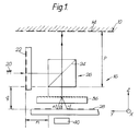
- a scale 10 extends in a plane defined as the XY plane and has markings 14 which extend parallel to the X direction and are spaced in the Y direction.
- a readhead 16 is movable relative to the scale in the X,Y and Z directions. The purpose of the readhead however is merely to measure displacement relative to a datum in the Y direction.
- the readhead 16 comprises a diffuse light source 20 provided adjacent an index grating 22, which has lines extending parallel to the X direction, spaced in the Z direction, and extending in the XZ plane.
- the beam of light generated by the light source 20 passes through the index grating 22 travelling substantially in the Y direction and is then incident upon a semi-silvered mirror 24 of a beam splitter cube 26.
- the mirror 24 directs the light beam through 90°, and onto the scale 10 in a direction perpendicular to the plane of the scale.
- Light reflected off the scale 10 travels back along its path perpendicular to the plane of the scale 10, through the beam splitter cube 26.
- a periodic light pattern, formed by the interaction of the light passing through the index grating 22 with the scale 10 is generated in the plane of an analyser grating 28; the analyser grating 28 has lines extending in the X direction, spaced in the Y direction, and the grating 28 extends in the XY plane substantially parallel to the scale 10.
- Relative movement of the readhead and the scale 10 in the Y direction results in the periodic light pattern generated in the plane of the analyser grating 28 moving relative to the analyser grating 28, thereby producing a modulation of light intensity indicative of the relative movement between the readhead and scale 10, which is detected by a photo-detector array 30.
- auxiliary grating 36 In order to determine the direction (i.e. +Y or -Y) of relative movement of the scale and readhead a plurality of phase-shifted light modulations are generated at the analyser grating 28 by an auxiliary grating 36.
- the auxiliary grating 36 extends in the XY plane, and has lines extending substantially parallel to the Y direction and spaced substantially in the X direction. However, the lines of the auxiliary grating 36 are skewed fractionally with respect to the Y direction (typically by the order of about one degree), and thus light passing through the auxiliary grating 36 will be diffracted into a plurality of orders (+1,0,-1) spaced apart in the X direction and each shifted fractionally relative to each other in the Y direction.
- a periodic light pattern will be produced at the analyser grating 28 in respect of each of the said orders, and thus when the readhead 16 moves relative the scale 10 in the Y direction each of the individual light patterns will produce a light intensity modulation.
- each of the patterns is shifted fractionally relative to each other image in the Y direction, a plurality of intensity modulations occurring in a phase-shifted relationship will result.
- the construction and function of the auxiliary grating 36 are described more fully in our co-pending international application case WO 89/05440.
- Each individual intensity modulation is focused by focusing optics (not shown) onto a photo-detector of a photo-detector array 40, which generates an electrical signal corresponding to the intensity of light incident thereon.
- the distance between the index grating 22 and the scale 10 must be equal to the distance between the scale 10 and the analyser grating 28.
- This condition is automatically fulfilled provided the readhead is constructed so that the distances q and r are equal, since the distance p is common to both the incident and reflected paths.
- the commonality of the distance p to both the incident and reflected paths makes the readhead insensitive to variations in the distance between the scale 10 and readhead, i.e. movements of the readhead relative to the scale 10 in the Z direction.
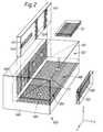
- a practical embodiment of a three-dimensional transducer arrangement for use in a measuring probe such as the probe mentioned above is illustrated.
- the readhead system 100 would be supported on the fixed part of a measuring probe, whereas the three scales 110,120,130 are provided on the movable (i.e. stylus-carrying) structure of such a measuring probe.
- the transducer system 100 comprises a right-angle bracket 140, which performs a supporting function for all the optical elements which make up the readhead system 100.
- the readhead system 100 consists of three individual readheads 142,144,146 for measuring displacement of the movable structure relative to the fixed structure in the X,Y and Z directions respectively.
- Each of the readheads has an emitter and a detector carried in the right-angle bracket 140, and for clarity these are schematically indicated in Fig 2 by the letters E and D respectively.
- Each individual readhead 142,144,146 comprises an index and analyser grating; for example readhead 144 comprises an index grating 148 and an analyser grating 150. Both the index grating 148 and analyser grating 150 are supported by the bracket 140.
- An auxiliary grating 152 provided to generate plurality of phase-shifted light intensity modulations at the surface of the analyser grating 150, is positioned directly in front of the analyser grating 150.
- the auxiliary grating 152 is provided in aperture 154 which restricts the amount of light passing through the grating 152; this provides easier separation of the phase-shifted light intensity modulations at the surface of the analyser 150.
- a single beam splitting element 156 is provided for all the readheads, the beam splitter 156 taking the form of a rectangular parallelepiped.
- index and analyser gratings on the readheads 142,146 extend in the same direction, a single grating may be used for each of the index and analyser gratings of the readheads 142 or 146.
- Each of the readheads 142,146 has an auxiliary grating 158,160, serving the same function as for the readhead 144.
- both the index and analyser gratings of the readheads 142,144,146 are provided on a single glass plate, as are the auxiliary gratings 152,158,160. This provides easier assembly of the readhead system 100.
- auxiliary gratings it is not essential to employ auxiliary gratings to generate phase-shifted light intensity modulations.
- Other means may be employed such as the provision of a plurality of offset analyser gratings each of which yields a distinct phase.
- An analyser as described in GB 1,231,029 may be provided.
Landscapes
- Physics & Mathematics (AREA)
- General Physics & Mathematics (AREA)
- Optical Transform (AREA)
Applications Claiming Priority (2)
| Application Number | Priority Date | Filing Date | Title |
|---|---|---|---|
| GB909023659A GB9023659D0 (en) | 1990-10-31 | 1990-10-31 | Opto-electronic scale reading apparatus |
| GB9023659 | 1990-10-31 |
Publications (1)
| Publication Number | Publication Date |
|---|---|
| EP0484104A1 true EP0484104A1 (de) | 1992-05-06 |
Family
ID=10684635
Family Applications (1)
| Application Number | Title | Priority Date | Filing Date |
|---|---|---|---|
| EP91309981A Ceased EP0484104A1 (de) | 1990-10-31 | 1991-10-29 | Optoelektronische Skalenablesevorrichtung |
Country Status (3)
| Country | Link |
|---|---|
| US (1) | US5184014A (de) |
| EP (1) | EP0484104A1 (de) |
| GB (1) | GB9023659D0 (de) |
Cited By (5)
| Publication number | Priority date | Publication date | Assignee | Title |
|---|---|---|---|---|
| EP0718601A3 (de) * | 1994-12-22 | 1997-06-18 | Renishaw Plc | Opto-elektronischer Skalenableseapparat |
| EP2058630A1 (de) | 2007-11-12 | 2009-05-13 | FAGOR, S.Coop. | Lesekopf für ein optoelektronisches Messgerät |
| EP2226613A1 (de) * | 2009-03-02 | 2010-09-08 | Fagor, S. Coop. | Lesekopf für ein optisches Positionsmessgerät |
| CN105606033A (zh) * | 2016-03-18 | 2016-05-25 | 清华大学深圳研究生院 | 绝对式光栅尺、其主光栅及其测量方法 |
| CN105758435A (zh) * | 2016-04-14 | 2016-07-13 | 清华大学深圳研究生院 | 一种绝对式光栅尺 |
Families Citing this family (3)
| Publication number | Priority date | Publication date | Assignee | Title |
|---|---|---|---|---|
| EP0843159A3 (de) * | 1991-11-06 | 1999-06-02 | Renishaw Transducer Systems Limited | Opto-elektronischer Skalenableseapparat |
| GB9924331D0 (en) * | 1999-10-15 | 1999-12-15 | Renishaw Plc | Scale reading apparatus |
| GB0004120D0 (en) * | 2000-02-23 | 2000-04-12 | Renishaw Plc | Opto-electronic scale reading apparatus |
Citations (3)
| Publication number | Priority date | Publication date | Assignee | Title |
|---|---|---|---|---|
| DE2207132A1 (de) * | 1972-02-16 | 1973-08-30 | Heidenhain Gmbh Dr Johannes | Anordnung zum messen der relativlage zweier zueinander beweglicher teile |
| EP0209340A2 (de) * | 1985-07-19 | 1987-01-21 | Dr. Johannes Heidenhain GmbH | Positionsmessvorrichtung mit optischen Gittern |
| WO1987007945A1 (en) * | 1986-06-21 | 1987-12-30 | Renishaw Plc | Opto-electronic scale-reading apparatus |
Family Cites Families (6)
| Publication number | Priority date | Publication date | Assignee | Title |
|---|---|---|---|---|
| GB1231029A (de) * | 1968-12-13 | 1971-05-05 | ||
| GB1504691A (en) * | 1974-03-15 | 1978-03-22 | Nat Res Dev | Measurement apparatus |
| GB1551217A (en) * | 1975-05-13 | 1979-08-22 | Renishaw Electrical Ltd | Displacement measuring apparatus |
| NL8601876A (nl) * | 1986-07-18 | 1988-02-16 | Philips Nv | Inrichting voor het aftasten van een optische registratiedrager. |
| GB8729066D0 (en) * | 1987-12-12 | 1988-01-27 | Renishaw Plc | Opto-electronic scale-reading apparatus |
| US5064290A (en) * | 1987-12-12 | 1991-11-12 | Renishaw Plc | Opto-electronic scale-reading apparatus wherein phase-separated secondary orders of diffraction are generated |
-
1990
- 1990-10-31 GB GB909023659A patent/GB9023659D0/en active Pending
-
1991
- 1991-10-29 EP EP91309981A patent/EP0484104A1/de not_active Ceased
- 1991-10-30 US US07/785,090 patent/US5184014A/en not_active Expired - Fee Related
Patent Citations (3)
| Publication number | Priority date | Publication date | Assignee | Title |
|---|---|---|---|---|
| DE2207132A1 (de) * | 1972-02-16 | 1973-08-30 | Heidenhain Gmbh Dr Johannes | Anordnung zum messen der relativlage zweier zueinander beweglicher teile |
| EP0209340A2 (de) * | 1985-07-19 | 1987-01-21 | Dr. Johannes Heidenhain GmbH | Positionsmessvorrichtung mit optischen Gittern |
| WO1987007945A1 (en) * | 1986-06-21 | 1987-12-30 | Renishaw Plc | Opto-electronic scale-reading apparatus |
Cited By (7)
| Publication number | Priority date | Publication date | Assignee | Title |
|---|---|---|---|---|
| EP0718601A3 (de) * | 1994-12-22 | 1997-06-18 | Renishaw Plc | Opto-elektronischer Skalenableseapparat |
| US5726442A (en) * | 1994-12-22 | 1998-03-10 | Renishaw Plc | Opto-electronic scale reading apparatus having light-transmissive phase-encoding array of elongate spectral encoding elements |
| EP2058630A1 (de) | 2007-11-12 | 2009-05-13 | FAGOR, S.Coop. | Lesekopf für ein optoelektronisches Messgerät |
| EP2226613A1 (de) * | 2009-03-02 | 2010-09-08 | Fagor, S. Coop. | Lesekopf für ein optisches Positionsmessgerät |
| CN105606033A (zh) * | 2016-03-18 | 2016-05-25 | 清华大学深圳研究生院 | 绝对式光栅尺、其主光栅及其测量方法 |
| CN105606033B (zh) * | 2016-03-18 | 2018-04-20 | 清华大学深圳研究生院 | 绝对式光栅尺、其主光栅及其测量方法 |
| CN105758435A (zh) * | 2016-04-14 | 2016-07-13 | 清华大学深圳研究生院 | 一种绝对式光栅尺 |
Also Published As
| Publication number | Publication date |
|---|---|
| US5184014A (en) | 1993-02-02 |
| GB9023659D0 (en) | 1990-12-12 |
Similar Documents
| Publication | Publication Date | Title |
|---|---|---|
| US5214280A (en) | Photoelectric position detector with offset phase grating scales | |
| JPS6333604A (ja) | 相対変位測定装置 | |
| EP1475613B1 (de) | Kodierer mit faseroptischen Empfängerkanälen | |
| JPH09196705A (ja) | 変位測定装置 | |
| JPH0131127B2 (de) | ||
| US4025197A (en) | Novel technique for spot position measurement | |
| US5127733A (en) | Integrated optical precision measuring device | |
| NL8005258A (nl) | Interferometer. | |
| US5184014A (en) | Opto-electronic scale reading apparatus | |
| JPH0652170B2 (ja) | 光結像式非接触位置測定装置 | |
| JPH0711433B2 (ja) | 光電位置測定装置 | |
| JP2764373B2 (ja) | 多座標測定装置 | |
| JPS58191907A (ja) | 移動量測定方法 | |
| JPH048724B2 (de) | ||
| JP2001141521A (ja) | 位置を測定しかつ案内誤差を算出する装置 | |
| JP2562479B2 (ja) | 反射式xyエンコーダ | |
| US6965437B2 (en) | Scanning unit for an optical position measuring device | |
| US7161139B2 (en) | Position-measuring system and method for operating a position-measuring system | |
| JPH06174424A (ja) | 測長または測角装置 | |
| JPS632323B2 (de) | ||
| US9638514B2 (en) | Optical position-measuring device | |
| US11353583B2 (en) | Optical position-measurement device with varying focal length along a transverse direction | |
| JP2503561B2 (ja) | レ―ザ―干渉式エンコ―ダ | |
| EP0310231B1 (de) | Optischer Messapparat | |
| JPH09126818A (ja) | 光電測長または測角装置 |
Legal Events
| Date | Code | Title | Description |
|---|---|---|---|
| PUAI | Public reference made under article 153(3) epc to a published international application that has entered the european phase |
Free format text: ORIGINAL CODE: 0009012 |
|
| AK | Designated contracting states |
Kind code of ref document: A1 Designated state(s): CH DE FR GB IT LI SE |
|
| 17P | Request for examination filed |
Effective date: 19921102 |
|
| 17Q | First examination report despatched |
Effective date: 19940331 |
|
| STAA | Information on the status of an ep patent application or granted ep patent |
Free format text: STATUS: THE APPLICATION HAS BEEN REFUSED |
|
| 18R | Application refused |
Effective date: 19940917 |