EP0484075B1 - Motorcycle radial tyre - Google Patents
Motorcycle radial tyre Download PDFInfo
- Publication number
- EP0484075B1 EP0484075B1 EP91309924A EP91309924A EP0484075B1 EP 0484075 B1 EP0484075 B1 EP 0484075B1 EP 91309924 A EP91309924 A EP 91309924A EP 91309924 A EP91309924 A EP 91309924A EP 0484075 B1 EP0484075 B1 EP 0484075B1
- Authority
- EP
- European Patent Office
- Prior art keywords
- belt
- tyre
- cords
- carcass
- bead
- Prior art date
- Legal status (The legal status is an assumption and is not a legal conclusion. Google has not performed a legal analysis and makes no representation as to the accuracy of the status listed.)
- Expired - Lifetime
Links
Images


Classifications
-
- B—PERFORMING OPERATIONS; TRANSPORTING
- B60—VEHICLES IN GENERAL
- B60C—VEHICLE TYRES; TYRE INFLATION; TYRE CHANGING; CONNECTING VALVES TO INFLATABLE ELASTIC BODIES IN GENERAL; DEVICES OR ARRANGEMENTS RELATED TO TYRES
- B60C9/00—Reinforcements or ply arrangement of pneumatic tyres
- B60C9/02—Carcasses
- B60C9/14—Carcasses built-up with sheets, webs, or films of homogeneous material, e.g. synthetics, sheet metal, rubber
-
- B—PERFORMING OPERATIONS; TRANSPORTING
- B60—VEHICLES IN GENERAL
- B60C—VEHICLE TYRES; TYRE INFLATION; TYRE CHANGING; CONNECTING VALVES TO INFLATABLE ELASTIC BODIES IN GENERAL; DEVICES OR ARRANGEMENTS RELATED TO TYRES
- B60C15/00—Tyre beads, e.g. ply turn-up or overlap
- B60C15/06—Flipper strips, fillers, or chafing strips and reinforcing layers for the construction of the bead
- B60C15/0603—Flipper strips, fillers, or chafing strips and reinforcing layers for the construction of the bead characterised by features of the bead filler or apex
-
- B—PERFORMING OPERATIONS; TRANSPORTING
- B60—VEHICLES IN GENERAL
- B60C—VEHICLE TYRES; TYRE INFLATION; TYRE CHANGING; CONNECTING VALVES TO INFLATABLE ELASTIC BODIES IN GENERAL; DEVICES OR ARRANGEMENTS RELATED TO TYRES
- B60C9/00—Reinforcements or ply arrangement of pneumatic tyres
- B60C9/18—Structure or arrangement of belts or breakers, crown-reinforcing or cushioning layers
- B60C9/20—Structure or arrangement of belts or breakers, crown-reinforcing or cushioning layers built-up from rubberised plies each having all cords arranged substantially parallel
- B60C9/22—Structure or arrangement of belts or breakers, crown-reinforcing or cushioning layers built-up from rubberised plies each having all cords arranged substantially parallel the plies being arranged with all cords disposed along the circumference of the tyre
-
- B—PERFORMING OPERATIONS; TRANSPORTING
- B60—VEHICLES IN GENERAL
- B60C—VEHICLE TYRES; TYRE INFLATION; TYRE CHANGING; CONNECTING VALVES TO INFLATABLE ELASTIC BODIES IN GENERAL; DEVICES OR ARRANGEMENTS RELATED TO TYRES
- B60C13/00—Tyre sidewalls; Protecting, decorating, marking, or the like, thereof
- B60C13/04—Tyre sidewalls; Protecting, decorating, marking, or the like, thereof having annular inlays or covers, e.g. white sidewalls
- B60C2013/045—Tyre sidewalls; Protecting, decorating, marking, or the like, thereof having annular inlays or covers, e.g. white sidewalls comprising different sidewall rubber layers
-
- Y—GENERAL TAGGING OF NEW TECHNOLOGICAL DEVELOPMENTS; GENERAL TAGGING OF CROSS-SECTIONAL TECHNOLOGIES SPANNING OVER SEVERAL SECTIONS OF THE IPC; TECHNICAL SUBJECTS COVERED BY FORMER USPC CROSS-REFERENCE ART COLLECTIONS [XRACs] AND DIGESTS
- Y10—TECHNICAL SUBJECTS COVERED BY FORMER USPC
- Y10T—TECHNICAL SUBJECTS COVERED BY FORMER US CLASSIFICATION
- Y10T152/00—Resilient tires and wheels
- Y10T152/10—Tires, resilient
- Y10T152/10495—Pneumatic tire or inner tube
- Y10T152/10765—Characterized by belt or breaker structure
- Y10T152/10783—Reinforcing plies made up from wound narrow ribbons
-
- Y—GENERAL TAGGING OF NEW TECHNOLOGICAL DEVELOPMENTS; GENERAL TAGGING OF CROSS-SECTIONAL TECHNOLOGIES SPANNING OVER SEVERAL SECTIONS OF THE IPC; TECHNICAL SUBJECTS COVERED BY FORMER USPC CROSS-REFERENCE ART COLLECTIONS [XRACs] AND DIGESTS
- Y10—TECHNICAL SUBJECTS COVERED BY FORMER USPC
- Y10T—TECHNICAL SUBJECTS COVERED BY FORMER US CLASSIFICATION
- Y10T152/00—Resilient tires and wheels
- Y10T152/10—Tires, resilient
- Y10T152/10495—Pneumatic tire or inner tube
- Y10T152/10819—Characterized by the structure of the bead portion of the tire
- Y10T152/10837—Bead characterized by the radial extent of apex, flipper or chafer into tire sidewall
-
- Y—GENERAL TAGGING OF NEW TECHNOLOGICAL DEVELOPMENTS; GENERAL TAGGING OF CROSS-SECTIONAL TECHNOLOGIES SPANNING OVER SEVERAL SECTIONS OF THE IPC; TECHNICAL SUBJECTS COVERED BY FORMER USPC CROSS-REFERENCE ART COLLECTIONS [XRACs] AND DIGESTS
- Y10—TECHNICAL SUBJECTS COVERED BY FORMER USPC
- Y10T—TECHNICAL SUBJECTS COVERED BY FORMER US CLASSIFICATION
- Y10T152/00—Resilient tires and wheels
- Y10T152/10—Tires, resilient
- Y10T152/10495—Pneumatic tire or inner tube
- Y10T152/10855—Characterized by the carcass, carcass material, or physical arrangement of the carcass materials
- Y10T152/10864—Sidewall stiffening or reinforcing means other than main carcass plies or foldups thereof about beads
Definitions
- the present invention relates to a pneumatic tyre, more particularly a belted radial tyre for motorcycle use, in which high speed steering stability and durability are improved.
- a belted radial tyre provided with a carcass composed of one radial ply and a single jointless belt has been proposed, wherein the jointless belt is disposed between the carcass and a rubber tread and formed by spirally winding a cord around the carcass continuously from one edge to the other edge of the belt ply.
- a tyre having features according to the preamble of claim 1 is known, for example, from DE-A-3535064.
- a motorcycle radial tyre comprises a tread (2) curved so that the maximum cross sectional width of the tyre lies between the edges (E1,E2) of the tread 2, a pair of bead cores (5) disposed one in each bead (4), a carcass (6) having at least one ply of radially arranged organic fibre cords extending between the beads (4) and turned up around the bead cores (5) to form two turned up portions (6b) and one main portion (6a) of the carcass, , a first belt (7) disposed radially outside the carcass (6) and comprising one cord (11) or a plurality of parallel cords wound spirally so that the windings thereof are laid at small angles of 0 to 5 degrees with respect to the tyre equator (C), the cords (11) of the first belt having an elastic modulus of not less than 5884 N/mm2 (600 kgf/mm2), characterised by the radial height (Ht) of
- a motorcycle radial tyre 1 has a tread 2, a pair of axially spaced beads 4, and a pair of sidewalls 3 extending radially inwardly from the edges E1 and E2 of the tread to the beads.
- a pair of bead cores 5 are provided one disposed in each bead 4
- a carcass 6 extends between the beads 4 and is turned up around the bead cores 5 from the axially inside to outside thereof to form two turned up portions 6b and one main portion 6a of the carcass 6, and belts 7 and 8 are disposed radially outside the carcass 6 and inside the tread 2.
- the carcass 6 has at least one ply of cords arranged radially of the tyre at an angle of 60 to 90 degrees with respect to the tyre equator C.
- organic fibre cords e.g. nylon, rayon, polyester, aromatic polyamide or the like may be used.
- the radial height Ht of the radially outer edge of the above-mentioned carcass turned up portions 6b is more than 0.6 and less than 1.2 times the radial height Hs of the tread edges E1 and E2, both measured from the bead base line 15.
- the lateral stiffness of the sidewalls is too small and the sidewalls are subjected to excessive bending stress which lowers the durability, and further improves the steering response.
- a bead apex 9 made of hard rubber is disposed between each carcass turned up portion 6b and the carcass main portion 6a.
- the bead apex 9 extends taperingly, radially outwardly from the bead core 5.
- the radial height Ha of the radially outer edge L of the bead apex from the bead base line 15 is more than 0.5 times and less than 1.2 times the above-mentioned height Hs of the tread edge.
- the height Ha is less than 0.5 times the height Hs, the bending rigidity of the beads is decreased, and the bead durability is lost.
- a rubber tread is disposed radially outside the crown portion of the carcass to define the tread 2.
- the tread 2 is curved so that the maximum tyre cross section width lies between the tread edges E1 and E2.
- a pair of rubber sidewalls 13 are disposed axially outside the carcass 6 to provide the sidewall portions 3.
- Each sidewall 13 has a double-layered structure which comprises an axially inner sidewall 13a made of hard rubber and an axially outer sidewall 13b made of softer rubber, and the sidewall 13 extends between the bead 4 and the tread edge E1, E2.
- the belts in the example shown in Figure s 1 and 6 are a jointless belt 7 disposed on the radially outside of the carcass 6 and a breaker belt 8 comprising a radially outer ply 8a and a radially inner ply 8b both disposed radially outside the jointless belt 7.
- the belts in the example shown in Figures 2 and 7 are a jointless belt 7 and a breaker belt 8 comprising a radially inner ply 8b disposed on the radially outside of the carcass 6 and a radially outer ply 8a disposed radially outside the ply 8b, wherein the jointless belt 7 is disposed between the radially outside and inside plies 8a and 8b.
- the jointless belt 7 is formed by spirally winding at least one ribbon 10 of rubber.
- the ribbons are wound on the carcass.
- the ribbons are wound on the previously applied breaker belt 8b.
- Figure 3 shows the ribbon 10, in which one belt cord or a plurality of parallel belt cords, in this example two parallel cords 11, are embedded in rubber 12 along its longitudinal direction.
- organic fibre cords e.g. Teflon, aromatic polyamide, polyester or the like, or steel cords, having a high modulus of elasticity of not less than 5884 N/mm2 (600 kgf/mm2) may be used.
- aromatic polyamide fibre cords are used for their high modulus.
- the tread portion is not effectively reinforced, and high speed running performance and high speed durability are insufficient.
- the ribbon 10 has a flat rectangular cross sectional shape, and the distance N measured from each of the side edges 10a to the centre of the adjacent cord 11 is set to be not more than 1/2 of the belt cord pitch P.
- the jointless belt 7 comprises two axially divided pieces 7a and 7b disposed one on each side of the tyre equator C.
- each ribbon is wound spirally and continuously from a start point F1, F2 near the tread edge E1, E2 to an end point G on or near the tyre equator C so that the belt cords 11 are laid at small angles of 0 to 5 degrees with respect to the tyre equator C.
- the ribbons are wound around the crown portion of the carcass 6.
- the ribbons are wound around the radially inner breaker ply 8b.
- the windings of each ribbon are not overlapped. It is however, possible to overlap the side edges 10a of the windings over each other as shown in Figure 5 to prevent the windings from being loosened especially at the starting point of the winding, so that ply separation failure at the jointless belt edges is reduced.
- the edges 10a of the ribbon are preferably tapered.
- the windings of the ribbon 10 or the windings of the belt cords 11 in one belt piece 7a are laid at the same inclination angle as the other belt piece 7b, but in the opposite direction with respect to the tyre equator C.
- the belt pieces 7a and 7b are formed by winding ribbons starting from the axially outer edges F1 and F2 toward the tyre equator, the loosening of the windings of the ribbon 10 especially at the edges can be prevented.
- the width WB of the jointless belt 7 measured along the belt 7 between the edges thereof is more than 0.7 and less than 1.0 times the width Wt of the tread 2 measured along the tread face between the tread edges E1 and E2.
- width WB is greater than 1.0 times Wt, the rigidity of the sidewalls is excessively increased which deteriorates ride comfort.
- width WB is more than 0.85 times and less than 0.90 times the width Wt.
- each ply 8a, 8b is formed by winding a full width strip of unwoven fabric.
- the breaker cords in each ply are arranged at an angle (alpha) of 10 to 30 degrees with respect to the tyre equator C and are parallel to each other but crosswise to the breaker cords in the other ply.
- organic fibre cords e.g. nylon and the like having a lower elastic modulus in comparison with the above-mentioned belt cords 11 are used.
- the widths Wa and Wb of the radially inner and outer breaker plies 8a and 8b, respectively, are 2 to 5 mm greater than the width WB of the jointless belt 7.
- Test tyres of size 170/60VR17 having the tyre structure shown in Figure 1 and the specifications given in Table 1 were prepared and tested for the following tyre performance factors.
- Example tyres were superior in all respects (steering stability, high-speed running stability and resistance to nibbling, and further high-speed durability) to Reference tyres.
- the spiral winding directions in the belt pieces 7a and 7b are differed from each other, but they may be the same directions.
- the jointless belt may be formed by winding one ribbon 10 spirally and continuously from one edge to the other edge thereof.
Landscapes
- Engineering & Computer Science (AREA)
- Mechanical Engineering (AREA)
- Tires In General (AREA)
Description
- The present invention relates to a pneumatic tyre, more particularly a belted radial tyre for motorcycle use, in which high speed steering stability and durability are improved.
- In order to provide motorcycles with high-speed running stability during cornering and also straight running, a belted radial tyre provided with a carcass composed of one radial ply and a single jointless belt has been proposed, wherein the jointless belt is disposed between the carcass and a rubber tread and formed by spirally winding a cord around the carcass continuously from one edge to the other edge of the belt ply.
- In such a belted radial tyre, since the windings of the belt cord run almost parallel to the tyre equator, the hooping force of the belt in the tyre tread region is enhanced to improve durability in high-speed running. However, the lateral rigidity of the tread region and shoulder portions is not effectively increased by this, and the tyre has a problem of slow convergence or recovery from disturbances during cornering and straight running.
- Also problems of nibbling (wandering) and steering stability arise.
- A tyre having features according to the preamble of claim 1 is known, for example, from DE-A-3535064.
- It is an object of the present invention to provide a motorcycle radial tyre in which directional stability during high speed straight running and high speed cornering performance are improved, and at the same time the disturbance converging characteristic is improved to provide improved manoeuvrability, and further resistance to nibbling.
- According to one aspect of the present invention, a motorcycle radial tyre comprises a tread (2) curved so that the maximum cross sectional width of the tyre lies between the edges (E1,E2) of the
tread 2, a pair of bead cores (5) disposed one in each bead (4), a carcass (6) having at least one ply of radially arranged organic fibre cords extending between the beads (4) and turned up around the bead cores (5) to form two turned up portions (6b) and one main portion (6a) of the carcass, , a first belt (7) disposed radially outside the carcass (6) and comprising one cord (11) or a plurality of parallel cords wound spirally so that the windings thereof are laid at small angles of 0 to 5 degrees with respect to the tyre equator (C), the cords (11) of the first belt having an elastic modulus of not less than 5884 N/mm² (600 kgf/mm²), characterised by the radial height (Ht) of the radially outer edge of the carcass turned up portions from the bead base line (15) being more than 0.6 times and less than 1.2 times the radial height (Hs) of tread edges (E1,E2) from thebead base line 15, a second belt (8) disposed radially outside the first belt and comprising one ply of parallel organic fibre cords laid at at angle of 10 to 30 degrees with respect to the tyre equator, a bead apex (9) disposed between the main portion (6a) and each turned up portion (6b) of the carcass and extending radially outwardly from the bead core (5), the bead apex (9) being made of rubber having a Shore A hardness of 67 to 77 (JIS(A) hardness of 65 to 75), the radial height (Ha) of the radially outer edge of the bead apex (9) from the bead base line (15) being more than 0.5 and less than 1.2 times the radial height (Hs) of the tread edges (E1,E2). - Embodiments of the present invention will now be described in detail in conjunction with the accompanying drawings, in which:
- Figure 1 is a cross sectional view of a tyre according to the present invention;
- Figure 2 is a cross sectional view of another tyre according to the present invention;
- Figure 3 is an enlarged perspective view of a cord reinforced ribbon of rubber for making the jointless belt thereof;
- Figure 4 is a cross sectional view showing an example of winding the ribbon;
- Figure 5 is a cross sectional view showing another example of winding the ribbon;
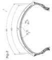
- Figure 6 is a developed plan view showing the arrangement of the carcass, jointless belt and breaker belt in the tyre of Figure 1; and
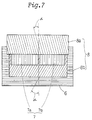
- Figure 7 is a developed plan view showing the arrangement of the carcass, jointless belt and breaker belt in the tyre of Figure 2.
- In the figures, a motorcycle radial tyre 1 has a
tread 2, a pair of axially spacedbeads 4, and a pair ofsidewalls 3 extending radially inwardly from the edges E1 and E2 of the tread to the beads. A pair ofbead cores 5 are provided one disposed in eachbead 4, acarcass 6 extends between thebeads 4 and is turned up around thebead cores 5 from the axially inside to outside thereof to form two turned upportions 6b and one main portion 6a of thecarcass 6, andbelts carcass 6 and inside thetread 2. - The
carcass 6 has at least one ply of cords arranged radially of the tyre at an angle of 60 to 90 degrees with respect to the tyre equator C. - For the carcass cords, organic fibre cords, e.g. nylon, rayon, polyester, aromatic polyamide or the like may be used.
- The radial height Ht of the radially outer edge of the above-mentioned carcass turned up
portions 6b is more than 0.6 and less than 1.2 times the radial height Hs of the tread edges E1 and E2, both measured from thebead base line 15. - If the height Ht is less than 0.6 times the tread edge height Hs, the lateral stiffness of the sidewalls is too small and the sidewalls are subjected to excessive bending stress which lowers the durability, and further improves the steering response.
- If the height Ht is more than 1.2 times Hs, the rigidity of the sidewalls is too great to give adequate ride comfort. Further, such a higher turnup is not preferable due to excessive weight of the tyre.
- Between each carcass turned up
portion 6b and the carcass main portion 6a, abead apex 9 made of hard rubber is disposed. - The
bead apex 9 extends taperingly, radially outwardly from thebead core 5. - The radial height Ha of the radially outer edge L of the bead apex from the
bead base line 15 is more than 0.5 times and less than 1.2 times the above-mentioned height Hs of the tread edge. - If the height Ha is less than 0.5 times the height Hs, the bending rigidity of the beads is decreased, and the bead durability is lost.
- A rubber tread is disposed radially outside the crown portion of the carcass to define the
tread 2. Thetread 2 is curved so that the maximum tyre cross section width lies between the tread edges E1 and E2. - A pair of
rubber sidewalls 13 are disposed axially outside thecarcass 6 to provide thesidewall portions 3. - Each
sidewall 13 has a double-layered structure which comprises an axially inner sidewall 13a made of hard rubber and an axiallyouter sidewall 13b made of softer rubber, and thesidewall 13 extends between thebead 4 and the tread edge E1, E2. - The belts in the example shown in
Figure s 1 and 6 are ajointless belt 7 disposed on the radially outside of thecarcass 6 and abreaker belt 8 comprising a radiallyouter ply 8a and a radiallyinner ply 8b both disposed radially outside thejointless belt 7. - The belts in the example shown in Figures 2 and 7 are a
jointless belt 7 and abreaker belt 8 comprising a radiallyinner ply 8b disposed on the radially outside of thecarcass 6 and a radiallyouter ply 8a disposed radially outside theply 8b, wherein thejointless belt 7 is disposed between the radially outside and insideplies - The
jointless belt 7 is formed by spirally winding at least oneribbon 10 of rubber. In Figure 1, the ribbons are wound on the carcass. In Figure 2, the ribbons are wound on the previously appliedbreaker belt 8b. - Figure 3 shows the
ribbon 10, in which one belt cord or a plurality of parallel belt cords, in this example twoparallel cords 11, are embedded inrubber 12 along its longitudinal direction. - For the
belt cords 11, organic fibre cords, e.g. Teflon, aromatic polyamide, polyester or the like, or steel cords, having a high modulus of elasticity of not less than 5884 N/mm² (600 kgf/mm²) may be used. - Preferably, aromatic polyamide fibre cords are used for their high modulus.
- If the elastic modulus is less than 5884 N/mm² (600 kgf/mm²), the tread portion is not effectively reinforced, and high speed running performance and high speed durability are insufficient.
- In this example, the
ribbon 10 has a flat rectangular cross sectional shape, and the distance N measured from each of theside edges 10a to the centre of theadjacent cord 11 is set to be not more than 1/2 of the belt cord pitch P. - In each of the embodiments shown in Figures 1 and 2, the
jointless belt 7 comprises two axially dividedpieces - In order to form those two pieces, two
ribbons 10 are used. As shown in Figure 4, each ribbon is wound spirally and continuously from a start point F1, F2 near the tread edge E1, E2 to an end point G on or near the tyre equator C so that thebelt cords 11 are laid at small angles of 0 to 5 degrees with respect to the tyre equator C. - In the embodiment shown in Figure 1, the ribbons are wound around the crown portion of the
carcass 6. In the embodiment shown in Figure 2, the ribbons are wound around the radiallyinner breaker ply 8b. - In Figure 4, the windings of each ribbon are not overlapped. It is however, possible to overlap the
side edges 10a of the windings over each other as shown in Figure 5 to prevent the windings from being loosened especially at the starting point of the winding, so that ply separation failure at the jointless belt edges is reduced. To smoothly overlap theedges 10a, theedges 10a of the ribbon are preferably tapered. - In the above-mentioned
belt 7, the windings of theribbon 10 or the windings of thebelt cords 11 in onebelt piece 7a are laid at the same inclination angle as theother belt piece 7b, but in the opposite direction with respect to the tyre equator C. - By winding two
ribbons 10 simultaneously to form thebelt pieces belt 7 is greatly reduced in comparison with a onepiece jointless belt. - As the
belt pieces ribbon 10 especially at the edges can be prevented. - In this embodiment, the width WB of the
jointless belt 7 measured along thebelt 7 between the edges thereof is more than 0.7 and less than 1.0 times the width Wt of thetread 2 measured along the tread face between the tread edges E1 and E2. - When the width WB is less than 0.7 times Wt, the stiffness of the tread shoulder region is too low which lowers the steering stability in quick turning.
- If the width WB is greater than 1.0 times Wt, the rigidity of the sidewalls is excessively increased which deteriorates ride comfort.
- More preferably the width WB is more than 0.85 times and less than 0.90 times the width Wt.
- In the above-mentioned
breaker belt 8, eachply - For the breaker cords, organic fibre cords, e.g. nylon and the like having a lower elastic modulus in comparison with the above-mentioned
belt cords 11 are used. - The widths Wa and Wb of the radially inner and
outer breaker plies jointless belt 7. - Test tyres of size 170/60VR17 having the tyre structure shown in Figure 1 and the specifications given in Table 1 were prepared and tested for the following tyre performance factors.
- 1) High speed straight running stability and High speed cornering stability
A motorcycle fitted on the rear wheel with the test tyre was run on a straight course at 260 km/Hr and around a 400 m radius curve course at 220 km/Hr, and the running stability was evaluated by a skilled test driver.
The stability is indicated by an index based on the assumption that Reference tyre 1 is 100. The larger the value, the better the stability. - 2) Convergence (Steering stability)
Convergence following disturbance during cornering and straight running was evaluated by the skilled test driver. - 3) High speed durability
Using a drum tyre tester, the running speed was increased every 10 minutes by a step of 10 km/Hr from an initial speed of 250 km/Hr, and the running distance until the tread or beads were cracked was measured. The tyre pressure was 294 kN/m² (3.0 kgf/cm²), and the tyre load was 355 kg.
The durability is indicated by an index based on the assumption that Reference tyre 1 is 100. The larger the value, the better the durability. - 4) Resistance to nibbling (Resistance to wandering)
While running on a test course provided with rain grooves and projections at a speed of 200 km/Hr, the resistance to nibbling was evaluated by the test driver. - Incidentally, in the above-mentioned tests, a 120/70R17 tyre was used for the front wheel. The specifications thereof are given in Table 2.
- Through the tests, it was confirmed that working Example tyres were superior in all respects (steering stability, high-speed running stability and resistance to nibbling, and further high-speed durability) to Reference tyres.
- In the above-mentioned two embodiments, the spiral winding directions in the
belt pieces - Further, the jointless belt may be formed by winding one
ribbon 10 spirally and continuously from one edge to the other edge thereof.

TABLE 2 Carcass No. of ply 2 Cord nylon 2/840d Cord count (ends/5cm) 55 Cord angle (deg.) 88 Ht/Hs 0.7 Belt No. of ply 2 Cord aramid 3/1500d Cord count (ends/5cm) 45 Cord angle (deg.) 17 Bead apex Ha/Hs 0.6
Claims (3)
- A motorcycle radial tyre comprising a tread (2) curved so that the maximum cross sectional width of the tyre lies between the edges (E1,E2) of the tread 2, a pair of bead cores (5) disposed one in each bead (4), a carcass (6) having at least one ply of radially arranged organic fibre cords extending between the beads (4) and turned up around the bead cores (5) to form two turned up portions (6b) and one main portion (6a) of the carcass, , a first belt (7) disposed radially outside the carcass (6) and comprising one cord (11) or a plurality of parallel cords wound spirally so that the windings thereof are laid at small angles of 0 to 5 degrees with respect to the tyre equator (C), the cords (11) of the first belt having an elastic modulus of not less than 5884 N/mm² (600 kgf/mm²), characterised by the radial height (Ht) of the radially outer edge of the carcass turned up portions from the bead base line (15) being more than 0.6 times and less than 1.2 times the radial height (Hs) of tread edges (E1,E2) from the bead base line 15, a second belt (8) disposed radially outside the first belt and comprising one ply of parallel organic fibre cords laid at at angle of 10 to 30 degrees with respect to the tyre equator, a bead apex (9) disposed between the main portion (6a) and each turned up portion (6b) of the carcass and extending radially outwardly from the bead core (5), the bead apex (9) being made of rubber having a Shore A hardness of 67 to 77 (JIS(A) hardness of 65 to 75), the radial height (Ha) of the radially outer edge of the bead apex (9) from the bead base line (15) being more than 0.5 and less than 1.2 times the radial height (Hs) of the tread edges (E1,E2).
- A motorcycle radial tyre according to claim 1, characterised in that said tyre is provide with a third belt (8b) disposed between the carcass (6) and the first belt (8a), and the third belt (8b) comprises one ply of parallel organic fibre cords laid at an angle of 10 to 30 degrees with respect to the tyre equator so that the cords thereof cross the cords of the second belt.
- A motorcycle radial tyre according to claim 1, characterised in that said tyre is provide with a third belt disposed radially outside the second belt, and the third belt comprises one ply of parallel organic fibre cords laid at an angle of 10 to 30 degrees with respect to the tyre equator so that the cords thereof cross the cords of the second belt.
Applications Claiming Priority (4)
| Application Number | Priority Date | Filing Date | Title |
|---|---|---|---|
| JP292528/90 | 1990-10-29 | ||
| JP29252890 | 1990-10-29 | ||
| JP3276943A JP2702835B2 (en) | 1990-10-29 | 1991-09-26 | Radial tires for motorcycles |
| JP276943/91 | 1991-09-26 |
Publications (2)
| Publication Number | Publication Date |
|---|---|
| EP0484075A1 EP0484075A1 (en) | 1992-05-06 |
| EP0484075B1 true EP0484075B1 (en) | 1994-12-14 |
Family
ID=26552176
Family Applications (1)
| Application Number | Title | Priority Date | Filing Date |
|---|---|---|---|
| EP91309924A Expired - Lifetime EP0484075B1 (en) | 1990-10-29 | 1991-10-28 | Motorcycle radial tyre |
Country Status (4)
| Country | Link |
|---|---|
| US (1) | US5385193A (en) |
| EP (1) | EP0484075B1 (en) |
| JP (1) | JP2702835B2 (en) |
| DE (1) | DE69105917T2 (en) |
Families Citing this family (24)
| Publication number | Priority date | Publication date | Assignee | Title |
|---|---|---|---|---|
| US5783004A (en) * | 1996-12-04 | 1998-07-21 | Sumitomo Rubber Industries, Ltd. | Motorcycle tire with three belt plies |
| JP3198077B2 (en) * | 1997-06-27 | 2001-08-13 | 住友ゴム工業株式会社 | Pneumatic tire |
| ES2188251T3 (en) | 1999-02-19 | 2003-06-16 | Michelin Soc Tech | TIRE FOR MOTORCYCLE PRESENTING A CROWN ARMOR WITH FABRIC OF CIRCUMFERENTIAL ELEMENTS. |
| US6668889B1 (en) | 1999-12-21 | 2003-12-30 | The Goodyear Tire & Rubber Company | Reinforcement package for tires |
| BR9917588A (en) * | 1999-12-21 | 2002-08-06 | Goodyear Tire & Rubber | Reinforcement package for tires |
| EP1338440B1 (en) * | 2002-02-14 | 2007-09-19 | Sumitomo Rubber Industries Ltd. | Pneumatic tire |
| JPWO2004014668A1 (en) * | 2002-08-09 | 2005-12-02 | 株式会社ブリヂストン | Pneumatic tires for motorcycles |
| JP4315820B2 (en) * | 2004-01-07 | 2009-08-19 | 株式会社ブリヂストン | Pneumatic tires for motorcycles |
| JP4463753B2 (en) * | 2005-10-28 | 2010-05-19 | 住友ゴム工業株式会社 | Motorcycle tires |
| JP4540587B2 (en) * | 2005-11-02 | 2010-09-08 | 株式会社ブリヂストン | Pneumatic tires for motorcycles |
| JP4829895B2 (en) | 2005-11-18 | 2011-12-07 | 株式会社ブリヂストン | Radial tires for motorcycles |
| JP4963860B2 (en) * | 2006-04-20 | 2012-06-27 | 株式会社ブリヂストン | Radial tires for motorcycles |
| US8056596B2 (en) * | 2007-10-22 | 2011-11-15 | The Goodyear Tire + Rubber Company, Inc. | Multiple ply modular construction |
| JP5277928B2 (en) * | 2008-12-15 | 2013-08-28 | 横浜ゴム株式会社 | Pneumatic tire |
| US9168789B2 (en) * | 2008-12-19 | 2015-10-27 | The Goodyear Tire & Rubber Company | Truck tire |
| JP4723659B2 (en) * | 2009-02-24 | 2011-07-13 | 住友ゴム工業株式会社 | Pneumatic tires for motorcycles |
| JP6083303B2 (en) * | 2013-04-03 | 2017-02-22 | 横浜ゴム株式会社 | Pneumatic tire |
| EP3064376B1 (en) * | 2013-10-29 | 2018-10-24 | Bridgestone Corporation | Tire |
| DE102013226442A1 (en) * | 2013-12-18 | 2015-06-18 | Continental Reifen Deutschland Gmbh | Vehicle tires |
| JP6320764B2 (en) | 2014-01-24 | 2018-05-09 | 株式会社ブリヂストン | Motorcycle tires |
| JP6200832B2 (en) * | 2014-02-26 | 2017-09-20 | 住友ゴム工業株式会社 | Pneumatic tires for motorcycles |
| JP6381075B2 (en) * | 2015-04-06 | 2018-08-29 | 住友ゴム工業株式会社 | Pneumatic tires for motorcycles |
| JP2022083810A (en) * | 2020-11-25 | 2022-06-06 | 住友ゴム工業株式会社 | Tire for motorcycle |
| JP2023145031A (en) * | 2022-03-28 | 2023-10-11 | 住友ゴム工業株式会社 | Motorcycle tire |
Family Cites Families (19)
| Publication number | Priority date | Publication date | Assignee | Title |
|---|---|---|---|---|
| BR6792110D0 (en) * | 1966-10-25 | 1973-06-12 | Pirelli | TROLLEY RING FOR PNEUMATICS WITH SEPARATE TIRES |
| BE754927A (en) * | 1969-08-19 | 1971-02-17 | Uniroyal Englebert France | BELTS TIRES |
| CH518192A (en) * | 1970-03-12 | 1972-01-31 | Pirelli | Tread ring for tread tire separated from the carcass |
| GB1487426A (en) * | 1974-09-17 | 1977-09-28 | Bekaert Sa Nv | Reinforcement of vehicle tyres |
| FR2473426A1 (en) * | 1979-12-06 | 1981-07-17 | Dunlop Ltd | PNEUMATIC HAVING A REINFORCING BELT, IN PARTICULAR FOR HEAVY WEIGHT |
| JPS5820503A (en) * | 1981-07-29 | 1983-02-07 | Bridgestone Corp | Pneumatic radial tire for motorcycle |
| JPS5893606A (en) * | 1981-11-27 | 1983-06-03 | Sumitomo Rubber Ind Ltd | Motorcycle |
| DE3375468D1 (en) * | 1982-04-16 | 1988-03-03 | Goodyear Tire & Rubber | Tread reinforcement structure for pneumatic tire |
| JPS58185304A (en) * | 1982-04-23 | 1983-10-29 | Bridgestone Corp | Pneumatic tire for motorcycle |
| GB8413093D0 (en) * | 1984-05-22 | 1984-06-27 | Apsley Metals Ltd | Tyres |
| JPS6185203A (en) * | 1984-10-02 | 1986-04-30 | Bridgestone Corp | Pneumatic radial tire for motorcycle |
| US5176770A (en) * | 1984-10-02 | 1993-01-05 | Bridgestone Corporation | Pneumatic belted tires for motorcycles |
| JPS6185202A (en) * | 1984-10-02 | 1986-04-30 | Bridgestone Corp | Radial tire for motorcycle |
| US4688615A (en) * | 1985-05-28 | 1987-08-25 | The Goodyear Tire & Rubber Company | Reinforcing structure for a rubber article |
| JPH01109106A (en) * | 1987-10-23 | 1989-04-26 | Bridgestone Corp | Pneumatic radial tire for motorcycle |
| JPH07102761B2 (en) * | 1988-09-26 | 1995-11-08 | 住友ゴム工業株式会社 | Radial tires for motorcycles |
| JP2691432B2 (en) * | 1988-12-16 | 1997-12-17 | 横浜ゴム株式会社 | Pneumatic tire |
| JP2908468B2 (en) * | 1989-05-23 | 1999-06-21 | 株式会社ブリヂストン | Radial tires for motorcycles |
| JPH045110A (en) * | 1990-04-20 | 1992-01-09 | Sumitomo Rubber Ind Ltd | Radial tire for motorcycle |
-
1991
- 1991-09-26 JP JP3276943A patent/JP2702835B2/en not_active Expired - Fee Related
- 1991-10-28 EP EP91309924A patent/EP0484075B1/en not_active Expired - Lifetime
- 1991-10-28 DE DE69105917T patent/DE69105917T2/en not_active Expired - Fee Related
-
1994
- 1994-01-12 US US08/180,500 patent/US5385193A/en not_active Expired - Lifetime
Also Published As
| Publication number | Publication date |
|---|---|
| EP0484075A1 (en) | 1992-05-06 |
| JP2702835B2 (en) | 1998-01-26 |
| DE69105917D1 (en) | 1995-01-26 |
| DE69105917T2 (en) | 1995-05-04 |
| JPH054503A (en) | 1993-01-14 |
| US5385193A (en) | 1995-01-31 |
Similar Documents
| Publication | Publication Date | Title |
|---|---|---|
| EP0484075B1 (en) | Motorcycle radial tyre | |
| US5415216A (en) | Passenger radial tire including bead reinforcement | |
| EP0463875B1 (en) | Motorcycle radial tyre | |
| EP0628435B1 (en) | Pneumatic motorcycle tyre | |
| US5400847A (en) | Radial tire for motorcycle including spiral cord belt | |
| EP0790143B1 (en) | Pneumatic radial tyre | |
| EP0595653B1 (en) | Pneumatic tyre | |
| EP1019257B1 (en) | Light weight aramid belted radial tire | |
| CA1330930C (en) | Pneumatic tire | |
| EP0467585B1 (en) | Radial tyre for a motorcycle | |
| EP0456438B1 (en) | Radial tyre for motorcycle | |
| EP0565339B1 (en) | A motorcycle tyre | |
| US6058997A (en) | Pneumatic radial tire having at least two zigzag belt layers | |
| EP1097824A2 (en) | Radial tyre for motorcycle | |
| EP0453295B1 (en) | Radial tyre for motorcycle | |
| EP0472425B1 (en) | Radial tyre | |
| EP0549311A1 (en) | Motorcycle radial tyre | |
| EP0465188B2 (en) | Passenger radial tyre | |
| JP3076514B2 (en) | Pneumatic radial tire | |
| JP3108531B2 (en) | Motorcycle tires | |
| EP0779163B1 (en) | Motorcycle tyre | |
| EP0477016B1 (en) | Motorcycle radial tyre | |
| US4522243A (en) | Reinforcing belt for tires with a radial carcass | |
| EP1226041A1 (en) | Motorcycle radial tyre | |
| JPH0725241B2 (en) | Pneumatic radial tires for passenger cars |
Legal Events
| Date | Code | Title | Description |
|---|---|---|---|
| PUAI | Public reference made under article 153(3) epc to a published international application that has entered the european phase |
Free format text: ORIGINAL CODE: 0009012 |
|
| AK | Designated contracting states |
Kind code of ref document: A1 Designated state(s): DE FR GB |
|
| 17P | Request for examination filed |
Effective date: 19920522 |
|
| 17Q | First examination report despatched |
Effective date: 19931126 |
|
| GRAA | (expected) grant |
Free format text: ORIGINAL CODE: 0009210 |
|
| AK | Designated contracting states |
Kind code of ref document: B1 Designated state(s): DE FR GB |
|
| REF | Corresponds to: |
Ref document number: 69105917 Country of ref document: DE Date of ref document: 19950126 |
|
| ET | Fr: translation filed | ||
| PLBE | No opposition filed within time limit |
Free format text: ORIGINAL CODE: 0009261 |
|
| STAA | Information on the status of an ep patent application or granted ep patent |
Free format text: STATUS: NO OPPOSITION FILED WITHIN TIME LIMIT |
|
| 26N | No opposition filed | ||
| REG | Reference to a national code |
Ref country code: GB Ref legal event code: IF02 |
|
| PGFP | Annual fee paid to national office [announced via postgrant information from national office to epo] |
Ref country code: GB Payment date: 20061025 Year of fee payment: 16 |
|
| PGFP | Annual fee paid to national office [announced via postgrant information from national office to epo] |
Ref country code: DE Payment date: 20061026 Year of fee payment: 16 |
|
| GBPC | Gb: european patent ceased through non-payment of renewal fee |
Effective date: 20071028 |
|
| PG25 | Lapsed in a contracting state [announced via postgrant information from national office to epo] |
Ref country code: DE Free format text: LAPSE BECAUSE OF NON-PAYMENT OF DUE FEES Effective date: 20080501 |
|
| REG | Reference to a national code |
Ref country code: FR Ref legal event code: ST Effective date: 20080630 |
|
| PGFP | Annual fee paid to national office [announced via postgrant information from national office to epo] |
Ref country code: FR Payment date: 20061010 Year of fee payment: 16 |
|
| PG25 | Lapsed in a contracting state [announced via postgrant information from national office to epo] |
Ref country code: GB Free format text: LAPSE BECAUSE OF NON-PAYMENT OF DUE FEES Effective date: 20071028 |
|
| PG25 | Lapsed in a contracting state [announced via postgrant information from national office to epo] |
Ref country code: FR Free format text: LAPSE BECAUSE OF NON-PAYMENT OF DUE FEES Effective date: 20071031 |