EP0483724B1 - Nonconsumable electrode for stainless steel welding and method of welding - Google Patents
Nonconsumable electrode for stainless steel welding and method of welding Download PDFInfo
- Publication number
- EP0483724B1 EP0483724B1 EP91118352A EP91118352A EP0483724B1 EP 0483724 B1 EP0483724 B1 EP 0483724B1 EP 91118352 A EP91118352 A EP 91118352A EP 91118352 A EP91118352 A EP 91118352A EP 0483724 B1 EP0483724 B1 EP 0483724B1
- Authority
- EP
- European Patent Office
- Prior art keywords
- stainless steel
- electrode
- welding
- discharge end
- arc discharge
- Prior art date
- Legal status (The legal status is an assumption and is not a legal conclusion. Google has not performed a legal analysis and makes no representation as to the accuracy of the status listed.)
- Expired - Lifetime
Links
Images

Classifications
-
- B—PERFORMING OPERATIONS; TRANSPORTING
- B23—MACHINE TOOLS; METAL-WORKING NOT OTHERWISE PROVIDED FOR
- B23K—SOLDERING OR UNSOLDERING; WELDING; CLADDING OR PLATING BY SOLDERING OR WELDING; CUTTING BY APPLYING HEAT LOCALLY, e.g. FLAME CUTTING; WORKING BY LASER BEAM
- B23K35/00—Rods, electrodes, materials, or media, for use in soldering, welding, or cutting
- B23K35/02—Rods, electrodes, materials, or media, for use in soldering, welding, or cutting characterised by mechanical features, e.g. shape
- B23K35/0205—Non-consumable electrodes; C-electrodes
Definitions
- This invention relates to an electrode and a method for welding stainless steel.
- the invention relates to the method of treating the working arc discharge end of a nonconsumable arc welding electrode for use in stainless steel welding.
- Nonconsumable electrodes often are used for welding together stainless steel objects.
- a stainless steel end plug is welded into one end opening of a stainless steel hollow tube. Fuel pellets are inserted through the open end of the tube which later is sealed with a second end plug.
- the end plug is welded to the tube by inert gas welding where an arc generated by a nonconsumable electrode and protected by a shielded atmosphere welds the joint to be formed.
- TIG tungsten inert gas
- the end plug and hollow tube have a mismatched sulfur content which causes arc wander ("blow") to occur in the direction of the stainless steel component having low sulfur.
- arc wander arc wander
- the end plug contains 30 ppm of sulfur
- the hollow tube contains 100 ppm sulfur
- the arc generated by the electrode will deflect toward the end plug, creating a weld profile having a low depth to width ratio. This results in a weaker fuel rod which may fail during operation.
- an electrode for arc welding of stainless steel which comprises a solid, nonconsumable rod of metallic material which is adapted to readily emit electrons upon an electric potential being applied thereto.
- the electrode includes a working arc discharge end and a layer of stainless steel is positioned on the working arc discharge end of the electrode.
- the electrode includes a substantially planar end portion and the layer of stainless steel is deposited on the substantially planar end portion.
- the stainless steel coating ranges from about .00254 to .0127 cm (0.001 to about 0.005 inches) in thickness.
- the nonconsumable electrode preferably is formed from a material comprising tungsten.
- the improved arc welding electrode is provided according to another aspect of the invention by depositing stainless steel on the working arc discharge end of a conventional inert gas welding electrode.
- the stainless steel can be deposited on the working arc discharge end of the electrode in one preferred method of the invention by positioning the working arc discharge end of the electrode in close proximity to a grounded piece of stainless steel.
- the electrode is electrically shorted to the stainless steel and the working arc discharge end sticks to the stainless steel.
- the working arc discharge end of the electrode is broken from the stainless steel so that a layer of stainless steel remains on the discharge end.
- FIG. 1 there is shown a conventional welding chamber for girth and seal welding a stainless steel end plug coaxially into the end of a stainless steel nuclear fuel rod.
- the welding electrode and method of the present invention is applicable to a wide variety of welding chambers and stainless steel objects to be welded, the present invention will be discussed in relation to the stainless steel welding of an end plug coaxially positioned in a nuclear fuel rod.
- the welding of a stainless steel end plug into a stainless steel nuclear fuel rod can involve the end plug and the nuclear fuel rod having mismatched sulfur contents.
- conventional TIG welding of stainless steel objects having mismatched sulfur content results in arc wander toward the stainless steel object having the lower sulfur content.
- a low depth to width profile is obtained resulting in a faulty joint.
- the method and electrode of this invention can minimize or eliminate the above problem and can be used in the stainless steel welding of any number of objects having mismatched sulfur contents thus improving the practicality of TIG welding of stainless steels having mismatched sulfur contents.
- the method and invention has been found workable with austenitic Stainless Steel AISI No. 304 and 308 stainless steel having a sulfur content as high as 0.030 percent.
- Other examples of the types of stainless steel especially workable with the present invention include AISI Nos. 201, 202, 301, 302, 302B, 304L, 305, 309, 309S, 310, 310S, 314, 316, 316L, 317, 321, 347, 348, 403, 405, 410, 414, 420, 429, 430, 431, 434, 440A, 440B, 440C, 442, 446, 501 and 502. It is believed that the method and electrode of the present invention is applicable for use with all different types of austenitic, martensitic and ferritic stainless steels which often contain nominal amounts of sulfur and thus suffer some degree of arc wander resulting from mismatched sulfur contents.
- the welding chamber includes a fuel rod receiving head 12 having an orifice 14 therethrough to receive a tubular nuclear fuel rod R.
- the receiving head 12 is secured by a press fit into a welding chamber access opening 16.
- the fuel rod R held by a grounded chuck 18, is advanced through the receiving head so that the end plug P engages an end stop 20.
- the chuck 18 is rotatable by drive means (not shown).
- the end stop 20 is rotatably mounted by a frictionless bearing 22 to an end stop support column 24 which is bolted to the welding chamber housing 26 by means of bolts and spacer bushings 28, to allow unimpeded rotation of the fuel rod R during girth welding.
- the end stop 20 is described more fully in EP-A-405 170, which falls within the terms of Art.54(3)EPC.
- the welding chamber 10 includes a conventional girth welding assembly indicated generally at 30, and is supported by a coupler 31 fixed to the welding chamber housing 26 and extending radially into the welding chamber 10.
- the girth welding assembly 30 is a conventional TIG welder and includes a power generator 34 having a nonconsumable tungsten electrode, indicated generally at 36, and a welding nozzle 38 for mixing an inert gas with the arc produced by the power generator 34.
- Power generator 34 is connected to a source of conventional power 34a.
- the welding nozzle 38 terminates in a tip 40 through which the tungsten electrode extends.
- a housing member 42 supports the welding nozzle 38 and tip.
- the tungsten electrode 36 extends the length of the power generator 34 and extends through the nozzle tip 40.
- Positioning clamp means in the nozzle clamps the electrode in a set position relative to the nozzle.
- an arc is generated between the tungsten electrode and the joint to be formed.
- the preferred inert gas is helium and is provided into the welding chamber by a gas supply.
- the inert gas envelope contained in the welding chamber surrounds the generated arc and tungsten electrode and prevents decomposition of the tungsten electrode.
- the tungsten electrode is not a filler-metal electrode and is not deposited in the weld.
- Inert gas welding tungsten electrodes are well known to those skilled in the art and are formed of a matrix material which consists primarily of tungsten and can also include Thorium Dioxide and/or have a coating of Lanthanum Oxide.
- the generated arc contacts the area of the joint to be formed and melts that area, resulting, when the metal is cool, in an acceptable weld.
- This type of nonconsumable electrode is different from consumable electrodes which are deposited in the weld, such as E308-15 commonly used in stainless steel welding with reverse polarity current.
- an AC power source (not shown) is preferred and is stabilized in the power generator by means conventional to the industry.
- tungsten is preferred for the electrode, this invention is considered to be applicable to other nonconsumable electrode materials which exhibit properties similar to tungsten.
- the tungsten electrode 36 of a preferred construction in accordance with the present invention includes a working arc discharge end 44 having a substantially flat, planar end portion 46 ( Figures 2 and 4) which extends through the nozzle tip 40.
- the position of the working arc discharge end 44 can be changed by clamping the electrode in a new position or moving the power generator 34 relative to the housing 26.
- the tungsten electrode 36 is adapted to readily emit electrons upon an electric potential being applied thereto.
- the tungsten electrode 36 used in the welding chamber 10 is approximately .0762 to .1586 cm (0.0300 to 0.0625 inches) in diameter.
- the working arc discharge end 44 of the nonconsumable electrode includes a stainless steel coating 48 deposited thereon.
- the coating ranges from .0025 to .0127 cm (0.001 to 0.005 inches) in thickness and is located on the substantially planar end portion 46 ( Figure 4).
- the stainless steel coating 48 reduces arc wander and allows deeper arc penetration during stainless steel welding of those objects having mismatched sulfur content.
- minute amounts of sulfur in the stainless steel coating provided according to this invention can aid in reducing the arc wander existing when stainless steel objects having mismatched sulfur content are welded. Therefore, it is believed desirable that the stainless steel coating include some nominal amount of sulfur and thus, the coating is preferably formed from a stainless steel of the type listed previously.
- the end stop 20 includes a front end configured to engage the end of the fuel rod end plug in a vacuum tight seal.
- the end plug P includes an axial opening 50 ( Figures 6 & 7) communicating with the interior of the fuel rod.
- the opening 50 communicates with an axial passage extending through the end stop 20.
- the end stop 20 includes a rearwardly extending gas passage tube 52 mounted in a support tube 54 which is disposed axially in the end stop support column 24.
- the gas passage tube 52 is mounted by conventional ball thrust bearing and radial ball bearings 58 which allow rotation of the end stop as described in the above-noted allowed patent application.
- a gas passage nozzle 60 extends radially through the support column 24 and communicates into the gas passage tube 52.
- the nozzle 60 communicates through a conventional valve V to a vacuum source 60a for creating a vacuum draw in the gas passage tube 52 and the end stop 20 for allowing evacuation of the fuel rod during girth welding. Additionally, the nozzle connects to a pressurized helium source 60b for pressurizing the fuel rod before seal welding. A vacuum is drawn to sufficiently reduce the pressure and the available oxygen within the fuel rod to minimize oxidation during girth welding.
- FIG. 2-5 there is illustrated one preferred manual method of placing the stainless steel coating 48 on the working arc discharge end 44 of the electrode.
- Other methods can include plasma spray, sputtering, dipping and the other metal deposition methods conventionally used in the industry.
- a scrap fuel rod and end plug are inserted within the welding chamber 10 and placed against the end stop 20.
- the electrode working arc discharge end is brought into contact with the scrap rod and then backed away from the joint approximately .0025 to .0076 cm (0.001 to 0.003 inches).
- the power generator 34 is activated and an arc is discharged from the tungsten electrode.
- the close distance between the working arc discharge end of the electrode and the grounded fuel rod R causes the electrode to short and stick to the fuel rod ( Figure 2).
- An operator manually grasps the upper end of the electrode and twists the electrode to break the electrode from the joint to be formed ( Figure 3).
- the manual method of the invention can be accomplished using an acceptable fuel rod, in which case the acceptable fuel rod can be positioned in the welding chamber 10 and the electrode shorted thereto. This is not preferred because the fuel rod R may be damaged.
- the electrode can be used in the nuclear fuel welding process by replacing the scrap fuel rod with an acceptable fuel rod and end plug to be welded.
- the working arc discharge end 44 of the electrode 36 is positioned to within .0381 to .051 cm (0.015 to 0.020 inches) of the joint to be formed.
- an electric potential Upon the application of an electric potential, an arc is generated between the electrode and the joint J to be formed.
- the arc is directed against the joint for welding, and because the welding is conducted using the electrode of this invention, significant arc wandering from the joint is prevented and a deeper arc penetration is obtained.
- the rod R is rotated in the chuck 18 by drive means (not shown) and a complete girth weld around the fuel rod is obtained (Figure 5).
- the stainless steel coating 48 is retained on the discharge end of the electrode during numerous welding operations.
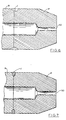
- Figure 6 shows an accurate illustration of a weld formed between a stainless steel end plug P and a stainless steel nuclear fuel rod R having mismatched sulfur contents where arc wander toward the end plug occurred. As illustrated, the weld is spread across the joint J and much of the weld penetration is directed against the end plug P and not the joint J. An untreated tungsten electrode was used.
- Figure 7 illustrates welding with a treated electrode in accordance with the present invention of a stainless steel end plug and stainless steel nuclear fuel rod having mismatched sulfur content where arc wander during welding was reduced and an acceptable depth to width ratio was obtained at the interface between the end plug and nuclear fuel rod.
- a tungsten electrode of this invention having a stainless steel coating was used in welding the joint of Figure 7.
- the tungsten electrode of the present invention is especially suited for critical tolerance stainless steel welding where the objects to be welded may have mismatched sulfur content. This often is the case when welding austenitic and other similar types of stainless steel objects such as a stainless steel end plug and a stainless steel nuclear fuel rod. Because small amounts of arc wander occurs when a conventional tungsten electrode is used to weld stainless steel objects having a mismatched sulfur content, this can create a weak weld ( Figure 6). The present invention minimizes or eliminates the arc wander problem and maintains a high quality weld.
Landscapes
- Engineering & Computer Science (AREA)
- Mechanical Engineering (AREA)
- Arc Welding In General (AREA)
- Butt Welding And Welding Of Specific Article (AREA)
Description
- This invention relates to an electrode and a method for welding stainless steel. In addition, the invention relates to the method of treating the working arc discharge end of a nonconsumable arc welding electrode for use in stainless steel welding.
- Nonconsumable electrodes often are used for welding together stainless steel objects. For example, in the manufacture of stainless steel nuclear fuel rods, a stainless steel end plug is welded into one end opening of a stainless steel hollow tube. Fuel pellets are inserted through the open end of the tube which later is sealed with a second end plug. The end plug is welded to the tube by inert gas welding where an arc generated by a nonconsumable electrode and protected by a shielded atmosphere welds the joint to be formed. One welding process commonly used is TIG (tungsten inert gas) arc welding.
- Often, the end plug and hollow tube have a mismatched sulfur content which causes arc wander ("blow") to occur in the direction of the stainless steel component having low sulfur. For example, if the end plug contains 30 ppm of sulfur, and the hollow tube contains 100 ppm sulfur, the arc generated by the electrode will deflect toward the end plug, creating a weld profile having a low depth to width ratio. This results in a weaker fuel rod which may fail during operation.
- Various proposals have been made for the improvement of tungsten electrodes, in general. For example, prior art tungsten electrodes have been treated for increasing electron emission and aiding in heat transfer. Examples of such prior art electrodes include German patents 1942632 and 2755213 which include the addition of a coating or the formation of a suitable electrode matrix of an oxide such as Lanthanum Oxide or Thorium Dioxide. Likewise, United States Patent No. 3,976,853 to Trattner, et al., discloses an improvement in the ignitability of a thoriated tungsten electrode by fuse sintering into a bore of the electrode a mass of electron emission increasing metal-nonmetal compounds. Despite the attention which has been given to improving tungsten electrodes, the arc wander problem has not been satisfactorily resolved.
- It is therefore an object of this invention to provide a method of welding stainless steel having a reduced arc wander and deeper arc penetration.
- It is another object of this invention to provide a method of treating the working arc discharge end of a nonconsumable arc welding electrode used in welding together stainless steel objects, such as an end plug into a hollow nuclear fuel rod, wherein the welding process has a reduced arc wander and deeper arc penetration.
- It is still another object of this invention to provide an electrode for arc welding of stainless steel having a reduced arc wander and deeper arc penetration when welding stainless steel objects having mismatched sulfur content.
- These and other objects of the present invention are accomplished by an electrode for arc welding of stainless steel which comprises a solid, nonconsumable rod of metallic material which is adapted to readily emit electrons upon an electric potential being applied thereto. The electrode includes a working arc discharge end and a layer of stainless steel is positioned on the working arc discharge end of the electrode. Advantageously, the electrode includes a substantially planar end portion and the layer of stainless steel is deposited on the substantially planar end portion. Preferably, the stainless steel coating ranges from about .00254 to .0127 cm (0.001 to about 0.005 inches) in thickness. The nonconsumable electrode preferably is formed from a material comprising tungsten.
- The improved arc welding electrode is provided according to another aspect of the invention by depositing stainless steel on the working arc discharge end of a conventional inert gas welding electrode. The stainless steel can be deposited on the working arc discharge end of the electrode in one preferred method of the invention by positioning the working arc discharge end of the electrode in close proximity to a grounded piece of stainless steel. The electrode is electrically shorted to the stainless steel and the working arc discharge end sticks to the stainless steel. The working arc discharge end of the electrode is broken from the stainless steel so that a layer of stainless steel remains on the discharge end.
- Some of the objects and advantages of the present invention having been stated, others will become apparent by reference to the following drawings, in which:
- Figure 1 is a partial, side sectional view of a welding chamber used for welding a stainless steel end plug into a stainless steel nuclear fuel rod in accordance with the present invention;
- Figure 2 is a side elevational view showing a nonconsumable electrode being shorted to the joint to be formed between a stainless steel end plug and a stainless steel nuclear fuel rod;
- Figure 3 is a side elevational view of the nonconsumable electrode being broken from the joint to be formed between the stainless steel end plug and nuclear fuel rod;
- Figure 4 is an enlarged view of the working arc discharge end of the nonconsumable electrode and showing in section a stainless steel coating thereon;
- Figure 5 is a side elevational view which illustrates welding of the stainless steel end plug into the stainless steel nuclear fuel rod with the treated electrode in accordance with the present invention;
- Figure 6 is an enlarged sectional view illustrating a stainless steel end plug welded into a stainless steel nuclear fuel rod by an untreated nonconsumable electrode and showing a weld with an unacceptable weld depth to width ratio; and
- Figure 7 is an enlarged sectional view illustrating a stainless steel end plug welded into a stainless steel nuclear fuel rod by a treated nonconsumable electrode in accordance with the present invention and showing an acceptable weld depth to width ratio.
- Referring to the drawings, and more particularly to Figure 1, there is shown a conventional welding chamber for girth and seal welding a stainless steel end plug coaxially into the end of a stainless steel nuclear fuel rod. Although the welding electrode and method of the present invention is applicable to a wide variety of welding chambers and stainless steel objects to be welded, the present invention will be discussed in relation to the stainless steel welding of an end plug coaxially positioned in a nuclear fuel rod.
- As indicated previously, the welding of a stainless steel end plug into a stainless steel nuclear fuel rod can involve the end plug and the nuclear fuel rod having mismatched sulfur contents. As is well known in the art, conventional TIG welding of stainless steel objects having mismatched sulfur content results in arc wander toward the stainless steel object having the lower sulfur content. Thus, a low depth to width profile is obtained resulting in a faulty joint. The method and electrode of this invention can minimize or eliminate the above problem and can be used in the stainless steel welding of any number of objects having mismatched sulfur contents thus improving the practicality of TIG welding of stainless steels having mismatched sulfur contents.
- The method and invention has been found workable with austenitic Stainless Steel AISI No. 304 and 308 stainless steel having a sulfur content as high as 0.030 percent. Other examples of the types of stainless steel especially workable with the present invention include AISI Nos. 201, 202, 301, 302, 302B, 304L, 305, 309, 309S, 310, 310S, 314, 316, 316L, 317, 321, 347, 348, 403, 405, 410, 414, 420, 429, 430, 431, 434, 440A, 440B, 440C, 442, 446, 501 and 502. It is believed that the method and electrode of the present invention is applicable for use with all different types of austenitic, martensitic and ferritic stainless steels which often contain nominal amounts of sulfur and thus suffer some degree of arc wander resulting from mismatched sulfur contents.
- Referring now to Figure 1, the welding chamber, indicated generally at 10, includes a fuel rod receiving head 12 having an
orifice 14 therethrough to receive a tubular nuclear fuel rod R. The receiving head 12 is secured by a press fit into a welding chamber access opening 16. The fuel rod R, held by agrounded chuck 18, is advanced through the receiving head so that the end plug P engages an end stop 20. Thechuck 18 is rotatable by drive means (not shown). The end stop 20 is rotatably mounted by a frictionless bearing 22 to an endstop support column 24 which is bolted to the welding chamber housing 26 by means of bolts andspacer bushings 28, to allow unimpeded rotation of the fuel rod R during girth welding. The end stop 20 is described more fully in EP-A-405 170, which falls within the terms of Art.54(3)EPC. - The welding chamber 10 includes a conventional girth welding assembly indicated generally at 30, and is supported by a
coupler 31 fixed to the welding chamber housing 26 and extending radially into the welding chamber 10. Thegirth welding assembly 30 is a conventional TIG welder and includes apower generator 34 having a nonconsumable tungsten electrode, indicated generally at 36, and awelding nozzle 38 for mixing an inert gas with the arc produced by thepower generator 34.Power generator 34 is connected to a source ofconventional power 34a. Thewelding nozzle 38 terminates in atip 40 through which the tungsten electrode extends. Ahousing member 42 supports thewelding nozzle 38 and tip. Thetungsten electrode 36 extends the length of thepower generator 34 and extends through thenozzle tip 40. Positioning clamp means in the nozzle (not shown) clamps the electrode in a set position relative to the nozzle. As is conventional with tungsten inert gas arc welding, an arc is generated between the tungsten electrode and the joint to be formed. The preferred inert gas is helium and is provided into the welding chamber by a gas supply. The inert gas envelope contained in the welding chamber surrounds the generated arc and tungsten electrode and prevents decomposition of the tungsten electrode. - As known to the skilled artisan, the tungsten electrode is not a filler-metal electrode and is not deposited in the weld. Inert gas welding tungsten electrodes are well known to those skilled in the art and are formed of a matrix material which consists primarily of tungsten and can also include Thorium Dioxide and/or have a coating of Lanthanum Oxide. The generated arc contacts the area of the joint to be formed and melts that area, resulting, when the metal is cool, in an acceptable weld. This type of nonconsumable electrode is different from consumable electrodes which are deposited in the weld, such as E308-15 commonly used in stainless steel welding with reverse polarity current. In the present invention, an AC power source (not shown) is preferred and is stabilized in the power generator by means conventional to the industry. Although tungsten is preferred for the electrode, this invention is considered to be applicable to other nonconsumable electrode materials which exhibit properties similar to tungsten.
- The
tungsten electrode 36 of a preferred construction in accordance with the present invention, includes a workingarc discharge end 44 having a substantially flat, planar end portion 46 (Figures 2 and 4) which extends through thenozzle tip 40. The position of the workingarc discharge end 44 can be changed by clamping the electrode in a new position or moving thepower generator 34 relative to the housing 26. Thetungsten electrode 36 is adapted to readily emit electrons upon an electric potential being applied thereto. Thetungsten electrode 36 used in the welding chamber 10 is approximately .0762 to .1586 cm (0.0300 to 0.0625 inches) in diameter. In accordance with the present invention, the working arc discharge end 44 of the nonconsumable electrode includes astainless steel coating 48 deposited thereon. The coating ranges from .0025 to .0127 cm (0.001 to 0.005 inches) in thickness and is located on the substantially planar end portion 46 (Figure 4). As will be explained in detail later, thestainless steel coating 48 reduces arc wander and allows deeper arc penetration during stainless steel welding of those objects having mismatched sulfur content. Although not wishing to be bound by theory, it is believed that minute amounts of sulfur in the stainless steel coating provided according to this invention can aid in reducing the arc wander existing when stainless steel objects having mismatched sulfur content are welded. Therefore, it is believed desirable that the stainless steel coating include some nominal amount of sulfur and thus, the coating is preferably formed from a stainless steel of the type listed previously. - The end stop 20 includes a front end configured to engage the end of the fuel rod end plug in a vacuum tight seal. As is conventional, the end plug P includes an axial opening 50 (Figures 6 & 7) communicating with the interior of the fuel rod. When the end plug P is engaged with the end stop 20 the
opening 50 communicates with an axial passage extending through the end stop 20. The end stop 20 includes a rearwardly extendinggas passage tube 52 mounted in asupport tube 54 which is disposed axially in the endstop support column 24. Thegas passage tube 52 is mounted by conventional ball thrust bearing andradial ball bearings 58 which allow rotation of the end stop as described in the above-noted allowed patent application. - A
gas passage nozzle 60 extends radially through thesupport column 24 and communicates into thegas passage tube 52. Thenozzle 60 communicates through a conventional valve V to avacuum source 60a for creating a vacuum draw in thegas passage tube 52 and the end stop 20 for allowing evacuation of the fuel rod during girth welding. Additionally, the nozzle connects to apressurized helium source 60b for pressurizing the fuel rod before seal welding. A vacuum is drawn to sufficiently reduce the pressure and the available oxygen within the fuel rod to minimize oxidation during girth welding. - Referring now to Figures 2-5, there is illustrated one preferred manual method of placing the
stainless steel coating 48 on the working arc discharge end 44 of the electrode. Other methods can include plasma spray, sputtering, dipping and the other metal deposition methods conventionally used in the industry. - In the preferred manual method, a scrap fuel rod and end plug are inserted within the welding chamber 10 and placed against the end stop 20. The electrode working arc discharge end is brought into contact with the scrap rod and then backed away from the joint approximately .0025 to .0076 cm (0.001 to 0.003 inches). The
power generator 34 is activated and an arc is discharged from the tungsten electrode. The close distance between the working arc discharge end of the electrode and the grounded fuel rod R causes the electrode to short and stick to the fuel rod (Figure 2). An operator manually grasps the upper end of the electrode and twists the electrode to break the electrode from the joint to be formed (Figure 3). As the electrode breaks from the stainless steel fuel rod, a stainless steel deposit ranging typically from .00254 to .0127 cm (0.001 to 0.005 inches) in thickness remains on the working arc discharge end of the electrode. Alternatively, the manual method of the invention can be accomplished using an acceptable fuel rod, in which case the acceptable fuel rod can be positioned in the welding chamber 10 and the electrode shorted thereto. This is not preferred because the fuel rod R may be damaged. - Thereupon, the electrode can be used in the nuclear fuel welding process by replacing the scrap fuel rod with an acceptable fuel rod and end plug to be welded. The working arc discharge end 44 of the
electrode 36 is positioned to within .0381 to .051 cm (0.015 to 0.020 inches) of the joint to be formed. Upon the application of an electric potential, an arc is generated between the electrode and the joint J to be formed. The arc is directed against the joint for welding, and because the welding is conducted using the electrode of this invention, significant arc wandering from the joint is prevented and a deeper arc penetration is obtained. During girth welding, the rod R is rotated in thechuck 18 by drive means (not shown) and a complete girth weld around the fuel rod is obtained (Figure 5). - The
stainless steel coating 48 is retained on the discharge end of the electrode during numerous welding operations. - Figure 6 shows an accurate illustration of a weld formed between a stainless steel end plug P and a stainless steel nuclear fuel rod R having mismatched sulfur contents where arc wander toward the end plug occurred. As illustrated, the weld is spread across the joint J and much of the weld penetration is directed against the end plug P and not the joint J. An untreated tungsten electrode was used. Figure 7 illustrates welding with a treated electrode in accordance with the present invention of a stainless steel end plug and stainless steel nuclear fuel rod having mismatched sulfur content where arc wander during welding was reduced and an acceptable depth to width ratio was obtained at the interface between the end plug and nuclear fuel rod. A tungsten electrode of this invention having a stainless steel coating was used in welding the joint of Figure 7.
- The tungsten electrode of the present invention is especially suited for critical tolerance stainless steel welding where the objects to be welded may have mismatched sulfur content. This often is the case when welding austenitic and other similar types of stainless steel objects such as a stainless steel end plug and a stainless steel nuclear fuel rod. Because small amounts of arc wander occurs when a conventional tungsten electrode is used to weld stainless steel objects having a mismatched sulfur content, this can create a weak weld (Figure 6). The present invention minimizes or eliminates the arc wander problem and maintains a high quality weld.
Claims (10)
- An electrode for arc welding of stainless steel comprising a solid, nonconsumable rod (36) of metallic material adapted to readily emit electrons upon an electrical potential being applied thereto, characterized in that the working arc discharge end (44) of the electrode includes a layer (48) of stainless steel applied thereon.
- The electrode according to claim 1, characterized in that said working arc discharge end (44) of the electrode is a substantially planar end portion (46) of said rod (36) with said layer (48) of stainless steel being located thereon.
- The electrode according to claim 1 or 2, characterized in that said stainless steel coating (48) ranges from about 0.025 mm to about 0.125 mm in thickness.
- The electrode according to any of claims 1 to 3, characterized in that said metallic rod material comprises tungsten.
- A method of making an electrode as claimed in any of claims 1 to 4, characterized in that the working arc discharge end of a solid, nonconsumable electrode rod (36) of metallic material is treated by applying a layer (48) of stainless steel thereon.
- The method according to claim 5, characterized in that applying said layer (48) of stainless steel to the working arc discharge end (44) of the electrode includes the steps of
positioning the working arc discharge end of the electrode in close proximity to a grounded piece of stainless steel,
electrically shorting the electrode (36) to the stainless steel so that the working arc discharge end sticks to the stainless steel, and
breaking the working arc discharge end (44) of the electrode from the stainless steel so that a layer (48) of stainless steel remains on the working arc discharge end of the electrode. - The method according to claim 6 wherein the working arc discharge end (44) of the electrode is positioned to a location within about 0,025 mm to about 0,075 mm from the grounded stainless steel at the time the electrode is shorted.
- The method according to claim 6 or 7, characterized in that said grounded piece of stainless steel is a workpiece of stainless steel to be welded, said steps of appyling said layer (48) of stainless steel to the working arc discharge end (44) of the electrode (36) being carried out before welding said stainless steel workpiece is commenced .
- A method of girth welding a stainless steel end plug (P) into a stainless steel nuclear fuel rod (R) using an electrode according to any of claims 1 to 4, characterized in that the working arc discharge end (44) of the electrode (36) is positioned to within about 0,35 mm to about 0,5 mm from the joint (J) to be formed during welding.
- The method according to claim 9, characterized by use of an electrode (36) of between about 0,75 mm and about 1,6 mm in diameter.
Applications Claiming Priority (2)
| Application Number | Priority Date | Filing Date | Title |
|---|---|---|---|
| US607924 | 1990-11-01 | ||
| US07/607,924 US5159174A (en) | 1990-11-01 | 1990-11-01 | Nonconsumable electrode for stainless steel welding and method of welding |
Publications (3)
| Publication Number | Publication Date |
|---|---|
| EP0483724A2 EP0483724A2 (en) | 1992-05-06 |
| EP0483724A3 EP0483724A3 (en) | 1993-06-16 |
| EP0483724B1 true EP0483724B1 (en) | 1995-03-01 |
Family
ID=24434278
Family Applications (1)
| Application Number | Title | Priority Date | Filing Date |
|---|---|---|---|
| EP91118352A Expired - Lifetime EP0483724B1 (en) | 1990-11-01 | 1991-10-28 | Nonconsumable electrode for stainless steel welding and method of welding |
Country Status (7)
| Country | Link |
|---|---|
| US (1) | US5159174A (en) |
| EP (1) | EP0483724B1 (en) |
| JP (1) | JPH05377A (en) |
| KR (1) | KR920009497A (en) |
| CA (1) | CA2054646A1 (en) |
| DE (1) | DE69107781T2 (en) |
| ES (1) | ES2071189T3 (en) |
Families Citing this family (8)
| Publication number | Priority date | Publication date | Assignee | Title |
|---|---|---|---|---|
| US4947258A (en) * | 1988-10-26 | 1990-08-07 | Array Technologies, Inc. | Image transducing apparatus |
| EP0869512A1 (en) * | 1997-04-02 | 1998-10-07 | Empresa Nacional Del Uranio, S.A. | Improvements to the ceramic nozzle flame outlets for welding plugs onto nuclear fuel rods, the manufacturing process for the rods and their corresponding plugs |
| JP5442456B2 (en) * | 2007-02-27 | 2014-03-12 | エクソンモービル アップストリーム リサーチ カンパニー | Corrosion-resistant alloy welds in carbon steel structures and pipelines adapted to large axial plastic strain |
| RU2520881C1 (en) * | 2013-03-06 | 2014-06-27 | Федеральное государственное бюджетное образовательное учреждение высшего профессионального образования "Волгоградский государственный университет" (ВолгГТУ) | Non-consumable electrode for arc welding |
| AU355902S (en) * | 2014-05-12 | 2014-06-13 | Electrolytic brush | |
| AU355903S (en) * | 2014-05-12 | 2014-06-13 | Electrolytic brush | |
| CN104107975B (en) * | 2014-07-23 | 2016-05-11 | 深圳市威勒达科技开发有限公司 | A kind of steel alloy-tungsten electrode |
| US10410754B2 (en) | 2016-10-11 | 2019-09-10 | Bwxt Mpower, Inc. | Resistance pressure weld for nuclear reactor fuel rod tube end plug |
Family Cites Families (12)
| Publication number | Priority date | Publication date | Assignee | Title |
|---|---|---|---|---|
| NL290760A (en) * | 1962-03-30 | |||
| AT279314B (en) * | 1968-08-30 | 1970-03-10 | Linde Ag | Use of an electrode consisting mainly of tungsten for plasma cutting |
| GB1316999A (en) * | 1970-06-19 | 1973-05-16 | Atomenergi Ab | Non-consumalbe electrode |
| BE757279A (en) * | 1970-10-09 | 1971-03-16 | Belgonucleaire Sa | WELDING PROCESS |
| GB1404374A (en) * | 1972-02-18 | 1975-08-28 | Matsushita Electric Ind Co Ltd | Tungsten inert gas arc welding striking device |
| US4001461A (en) * | 1973-03-30 | 1977-01-04 | David Grigorievich Bykhovsky | Method of producing electrode units for plasmatrons |
| DE2331558A1 (en) * | 1973-06-20 | 1975-01-16 | Siemens Ag | NON-MELTING ELECTRODE, IN PARTICULAR FOR TIG WELDING, AND PROCESS FOR THEIR PRODUCTION |
| IT1021136B (en) * | 1973-09-20 | 1978-01-30 | Westinghouse Electric Corp | EQUIPMENT FOR SEALING THE FUEL BARS OF A NUCLEAR REACTOR |
| JPS50154138A (en) * | 1974-06-04 | 1975-12-11 | ||
| DE2437776C3 (en) * | 1974-08-06 | 1981-02-26 | Messer Griesheim Gmbh, 6000 Frankfurt | Non-consumable electrode |
| DE2755213C2 (en) * | 1977-12-10 | 1982-05-06 | Fa. Dr. Eugen Dürrwächter DODUCO, 7530 Pforzheim | Non-consumable electrode and method of making it |
| CN1005732B (en) * | 1985-04-01 | 1989-11-08 | 上海灯泡厂 | W-ce electrode material, preparation technology and uses thereof |
-
1990
- 1990-11-01 US US07/607,924 patent/US5159174A/en not_active Expired - Fee Related
-
1991
- 1991-10-28 DE DE69107781T patent/DE69107781T2/en not_active Expired - Fee Related
- 1991-10-28 ES ES91118352T patent/ES2071189T3/en not_active Expired - Lifetime
- 1991-10-28 EP EP91118352A patent/EP0483724B1/en not_active Expired - Lifetime
- 1991-10-31 KR KR1019910019370A patent/KR920009497A/en not_active Application Discontinuation
- 1991-10-31 CA CA002054646A patent/CA2054646A1/en not_active Abandoned
- 1991-11-01 JP JP3313474A patent/JPH05377A/en not_active Withdrawn
Also Published As
| Publication number | Publication date |
|---|---|
| EP0483724A3 (en) | 1993-06-16 |
| JPH05377A (en) | 1993-01-08 |
| DE69107781T2 (en) | 1995-10-26 |
| US5159174A (en) | 1992-10-27 |
| CA2054646A1 (en) | 1992-05-02 |
| EP0483724A2 (en) | 1992-05-06 |
| KR920009497A (en) | 1992-06-25 |
| DE69107781D1 (en) | 1995-04-06 |
| ES2071189T3 (en) | 1995-06-16 |
Similar Documents
| Publication | Publication Date | Title |
|---|---|---|
| US5349152A (en) | Process for the electric welding of two weld parts | |
| KR100504296B1 (en) | Method of welding | |
| EP0483724B1 (en) | Nonconsumable electrode for stainless steel welding and method of welding | |
| US20040050824A1 (en) | Welding torch having collet and backcap adapted for securing engagement and method for operating same | |
| GB1341822A (en) | Welding methods and apparatus | |
| US4837419A (en) | Fuel rod end plug welding apparatus and method | |
| EP1459830B1 (en) | Tig welding method and welded object | |
| US4645903A (en) | Gas metal arc welding process | |
| US5097108A (en) | Conversion convergent nozzle assembly | |
| EP0663259B1 (en) | Welding apparatus for studs of annular cross-section | |
| EP0405170B1 (en) | End stop for welding sealing plugs of nuclear fuel rods | |
| KR920004269B1 (en) | Method of welding aluminum drive shaft components | |
| US5191185A (en) | Girth and seal welding apparatus | |
| US6069336A (en) | Plasma or TIG welding or cutting process with a non-oxidizing gas having a low H2 O and/or O2 impurity content | |
| US5041710A (en) | Conversion convergent nozzle assembly | |
| EP1570939A1 (en) | Submerged arc welding process | |
| DE2256050C3 (en) | Plasma jet generator | |
| EP0540746A1 (en) | Device and method for welding surface-treated metal | |
| JPS6245680B2 (en) | ||
| US4100389A (en) | Method of high speed gas shielded arc welding | |
| US3609275A (en) | Butt welding of tube plates and the like | |
| EP0697265A1 (en) | Gas metal arc welding process with rotating arc | |
| WO2024068182A1 (en) | Component such as a wearing part for an arc torch, in particular a plasma burner or plasma cutting torch, arc torch comprising same, and method of plasma cutting | |
| JPS61108475A (en) | Inert gas shield welding method | |
| DE2426669C3 (en) | Non-consumable electrode for arc machining of materials in an oxygen atmosphere |
Legal Events
| Date | Code | Title | Description |
|---|---|---|---|
| PUAI | Public reference made under article 153(3) epc to a published international application that has entered the european phase |
Free format text: ORIGINAL CODE: 0009012 |
|
| AK | Designated contracting states |
Kind code of ref document: A2 Designated state(s): BE DE ES FR GB IT SE |
|
| PUAL | Search report despatched |
Free format text: ORIGINAL CODE: 0009013 |
|
| AK | Designated contracting states |
Kind code of ref document: A3 Designated state(s): BE DE ES FR GB IT SE |
|
| 17P | Request for examination filed |
Effective date: 19930715 |
|
| 17Q | First examination report despatched |
Effective date: 19940608 |
|
| GRAA | (expected) grant |
Free format text: ORIGINAL CODE: 0009210 |
|
| AK | Designated contracting states |
Kind code of ref document: B1 Designated state(s): BE DE ES FR GB IT SE |
|
| REF | Corresponds to: |
Ref document number: 69107781 Country of ref document: DE Date of ref document: 19950406 |
|
| ET | Fr: translation filed | ||
| ITF | It: translation for a ep patent filed |
Owner name: MODIANO & ASSOCIATI S.R.L. |
|
| REG | Reference to a national code |
Ref country code: ES Ref legal event code: FG2A Ref document number: 2071189 Country of ref document: ES Kind code of ref document: T3 |
|
| PLBE | No opposition filed within time limit |
Free format text: ORIGINAL CODE: 0009261 |
|
| STAA | Information on the status of an ep patent application or granted ep patent |
Free format text: STATUS: NO OPPOSITION FILED WITHIN TIME LIMIT |
|
| 26N | No opposition filed | ||
| PGFP | Annual fee paid to national office [announced via postgrant information from national office to epo] |
Ref country code: GB Payment date: 19970917 Year of fee payment: 7 |
|
| PGFP | Annual fee paid to national office [announced via postgrant information from national office to epo] |
Ref country code: SE Payment date: 19971006 Year of fee payment: 7 |
|
| PGFP | Annual fee paid to national office [announced via postgrant information from national office to epo] |
Ref country code: FR Payment date: 19971007 Year of fee payment: 7 |
|
| PGFP | Annual fee paid to national office [announced via postgrant information from national office to epo] |
Ref country code: ES Payment date: 19971021 Year of fee payment: 7 |
|
| PGFP | Annual fee paid to national office [announced via postgrant information from national office to epo] |
Ref country code: DE Payment date: 19971030 Year of fee payment: 7 |
|
| PGFP | Annual fee paid to national office [announced via postgrant information from national office to epo] |
Ref country code: BE Payment date: 19971105 Year of fee payment: 7 |
|
| PG25 | Lapsed in a contracting state [announced via postgrant information from national office to epo] |
Ref country code: GB Free format text: LAPSE BECAUSE OF NON-PAYMENT OF DUE FEES Effective date: 19981028 |
|
| PG25 | Lapsed in a contracting state [announced via postgrant information from national office to epo] |
Ref country code: SE Free format text: LAPSE BECAUSE OF NON-PAYMENT OF DUE FEES Effective date: 19981029 Ref country code: ES Free format text: LAPSE BECAUSE OF NON-PAYMENT OF DUE FEES Effective date: 19981029 |
|
| PG25 | Lapsed in a contracting state [announced via postgrant information from national office to epo] |
Ref country code: BE Free format text: LAPSE BECAUSE OF NON-PAYMENT OF DUE FEES Effective date: 19981031 |
|
| BERE | Be: lapsed |
Owner name: WESTINGHOUSE ELECTRIC CORP. Effective date: 19981031 |
|
| GBPC | Gb: european patent ceased through non-payment of renewal fee |
Effective date: 19981028 |
|
| EUG | Se: european patent has lapsed |
Ref document number: 91118352.3 |
|
| PG25 | Lapsed in a contracting state [announced via postgrant information from national office to epo] |
Ref country code: FR Free format text: LAPSE BECAUSE OF NON-PAYMENT OF DUE FEES Effective date: 19990630 |
|
| REG | Reference to a national code |
Ref country code: FR Ref legal event code: ST |
|
| PG25 | Lapsed in a contracting state [announced via postgrant information from national office to epo] |
Ref country code: DE Free format text: LAPSE BECAUSE OF NON-PAYMENT OF DUE FEES Effective date: 19990803 |
|
| REG | Reference to a national code |
Ref country code: ES Ref legal event code: FD2A Effective date: 19991113 |
|
| PG25 | Lapsed in a contracting state [announced via postgrant information from national office to epo] |
Ref country code: IT Free format text: LAPSE BECAUSE OF NON-PAYMENT OF DUE FEES Effective date: 20051028 |