EP0483561B1 - Machining method and apparatus - Google Patents
Machining method and apparatus Download PDFInfo
- Publication number
- EP0483561B1 EP0483561B1 EP91117202A EP91117202A EP0483561B1 EP 0483561 B1 EP0483561 B1 EP 0483561B1 EP 91117202 A EP91117202 A EP 91117202A EP 91117202 A EP91117202 A EP 91117202A EP 0483561 B1 EP0483561 B1 EP 0483561B1
- Authority
- EP
- European Patent Office
- Prior art keywords
- coolant
- workpiece
- pressurized fluid
- machining
- operative
- Prior art date
- Legal status (The legal status is an assumption and is not a legal conclusion. Google has not performed a legal analysis and makes no representation as to the accuracy of the status listed.)
- Expired - Lifetime
Links
Images


Classifications
-
- B—PERFORMING OPERATIONS; TRANSPORTING
- B23—MACHINE TOOLS; METAL-WORKING NOT OTHERWISE PROVIDED FOR
- B23Q—DETAILS, COMPONENTS, OR ACCESSORIES FOR MACHINE TOOLS, e.g. ARRANGEMENTS FOR COPYING OR CONTROLLING; MACHINE TOOLS IN GENERAL CHARACTERISED BY THE CONSTRUCTION OF PARTICULAR DETAILS OR COMPONENTS; COMBINATIONS OR ASSOCIATIONS OF METAL-WORKING MACHINES, NOT DIRECTED TO A PARTICULAR RESULT
- B23Q11/00—Accessories fitted to machine tools for keeping tools or parts of the machine in good working condition or for cooling work; Safety devices specially combined with or arranged in, or specially adapted for use in connection with, machine tools
- B23Q11/10—Arrangements for cooling or lubricating tools or work
- B23Q11/1038—Arrangements for cooling or lubricating tools or work using cutting liquids with special characteristics, e.g. flow rate, quality
- B23Q11/1053—Arrangements for cooling or lubricating tools or work using cutting liquids with special characteristics, e.g. flow rate, quality using the cutting liquid at specially selected temperatures
-
- B—PERFORMING OPERATIONS; TRANSPORTING
- B23—MACHINE TOOLS; METAL-WORKING NOT OTHERWISE PROVIDED FOR
- B23F—MAKING GEARS OR TOOTHED RACKS
- B23F21/00—Tools specially adapted for use in machines for manufacturing gear teeth
- B23F21/02—Grinding discs; Grinding worms
- B23F21/023—Face-mill-type, i.e. cup-shaped, grinding wheels
-
- B—PERFORMING OPERATIONS; TRANSPORTING
- B23—MACHINE TOOLS; METAL-WORKING NOT OTHERWISE PROVIDED FOR
- B23Q—DETAILS, COMPONENTS, OR ACCESSORIES FOR MACHINE TOOLS, e.g. ARRANGEMENTS FOR COPYING OR CONTROLLING; MACHINE TOOLS IN GENERAL CHARACTERISED BY THE CONSTRUCTION OF PARTICULAR DETAILS OR COMPONENTS; COMBINATIONS OR ASSOCIATIONS OF METAL-WORKING MACHINES, NOT DIRECTED TO A PARTICULAR RESULT
- B23Q1/00—Members which are comprised in the general build-up of a form of machine, particularly relatively large fixed members
- B23Q1/0009—Energy-transferring means or control lines for movable machine parts; Control panels or boxes; Control parts
- B23Q1/0018—Energy-transferring means or control lines for movable machine parts; Control panels or boxes; Control parts comprising hydraulic means
- B23Q1/0027—Energy-transferring means or control lines for movable machine parts; Control panels or boxes; Control parts comprising hydraulic means between moving parts between which an uninterrupted energy-transfer connection is maintained
- B23Q1/0036—Energy-transferring means or control lines for movable machine parts; Control panels or boxes; Control parts comprising hydraulic means between moving parts between which an uninterrupted energy-transfer connection is maintained one of those parts being a tool
-
- B—PERFORMING OPERATIONS; TRANSPORTING
- B24—GRINDING; POLISHING
- B24B—MACHINES, DEVICES, OR PROCESSES FOR GRINDING OR POLISHING; DRESSING OR CONDITIONING OF ABRADING SURFACES; FEEDING OF GRINDING, POLISHING, OR LAPPING AGENTS
- B24B55/00—Safety devices for grinding or polishing machines; Accessories fitted to grinding or polishing machines for keeping tools or parts of the machine in good working condition
- B24B55/02—Equipment for cooling the grinding surfaces, e.g. devices for feeding coolant
-
- B—PERFORMING OPERATIONS; TRANSPORTING
- B24—GRINDING; POLISHING
- B24D—TOOLS FOR GRINDING, BUFFING OR SHARPENING
- B24D7/00—Bonded abrasive wheels, or wheels with inserted abrasive blocks, designed for acting otherwise than only by their periphery, e.g. by the front face; Bushings or mountings therefor
- B24D7/10—Bonded abrasive wheels, or wheels with inserted abrasive blocks, designed for acting otherwise than only by their periphery, e.g. by the front face; Bushings or mountings therefor with cooling provisions
-
- Y—GENERAL TAGGING OF NEW TECHNOLOGICAL DEVELOPMENTS; GENERAL TAGGING OF CROSS-SECTIONAL TECHNOLOGIES SPANNING OVER SEVERAL SECTIONS OF THE IPC; TECHNICAL SUBJECTS COVERED BY FORMER USPC CROSS-REFERENCE ART COLLECTIONS [XRACs] AND DIGESTS
- Y10—TECHNICAL SUBJECTS COVERED BY FORMER USPC
- Y10S—TECHNICAL SUBJECTS COVERED BY FORMER USPC CROSS-REFERENCE ART COLLECTIONS [XRACs] AND DIGESTS
- Y10S82/00—Turning
- Y10S82/90—Lathe thermal regulation
Definitions
- This invention relates generally to a method and apparatus for machining a workpiece at high speed while minimizing frictional heat generated during the machining process and more particularly to a method and apparatus that utilizes a temperature responsive coolant cooled by an expanding pressurized fluid such that its physical lubricity progressively increases with decreasing temperature to a consistency operative to reduce frictional heat generated during the machining process and to enhance conductive heat transfer into the machining tool.
- Frictional heat build-up during the machining process can create a plethora of problems including distortion and degradation (including burning) of either or both the workpiece and the machining tool as well as significantly shorten tool life resulting in substantially increased costs associated with machining the particular part.
- One machining process that is particularly prone to heat generation is grinding of which but one example is the grinding of vehicle differential ring gears that is hereinafter described in greater detail as an illustrative example.
- coolants petroleum and non-petroleum based metal working fluids hereinafter called coolants well known to those skilled in the art, such coolants have heretofor normally been used at or near ambient temperature and, when cooled, have been cooled down to near ambient temperature for re-use.
- US-A-4 829 895 discloses a method of reducing frictional heat generated while machining a workpiece with a machining tool, said method comprising the steps of directing a coolant (water) onto the workpiece and contacting the coolant with pressurized fluid (CO 2 ), and an apparatus for reducing frictional heat while machining a workpiece with a machining tool, said apparatus comprising a coolant (water), coolant delivery means for conveying the coolant onto the workpiece, pressurized fluid (CO 2 ) and pressurized fluid delivery means for contacting the coolant with the pressurized fluid.
- the temperature of the coolant is lowered by injecting pressurised carbon for freezing water that is contained by the coolant. During this , ice particles are generated. The ice particles absorbs heat when they melt and vaporize at the tool. Thus the ice particles carry away an increased quantity of heat to obtain the cooling effect.
- the ice and water mixture would not possess attractive lubricity characteristics; would not possess progressively increasing lubricity characteristics with decreasing temperature; and could conceivably lead to corrosion of the workpiece being machined especially ferrous alloys.
- the present invention eliminates the problems associated with the water and ice mixture previously described by cooling temperature responsive coolants to below ambient temperature to provide a consistency that greatly enhances its lubricating ability enabling substantially higher machining speeds while minimizing frictional heat build up during the machining process and enhancing conductive heat transfer into the machining tool.
- the preferred coolant consistency may be virtually a solid-like film to provide the degree of lubricity desired to minimize frictional heat generation during high speed machining operations.
- paste lubricants have been used in the past for certain machining operations, such pastes have commonly been difficult to apply; have characteristically been unable to be re-used because of inability to separate machined particles and other debris accumulated during the machining operation; and are difficult to apply in a repeatably uniform manner.
- the cooled coolants of the present invention are able to be applied separately or together, commonly at ambient temperature as fluid/liquids or gas/liquids and, as such, can be applied with a high degree of uniform repeatability and, upon returning to ambient temperature, can be cleaned (such as by filtering) for re-use.
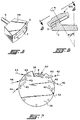
- An exemplary workpiece for use with the method and apparatus of the invention is vehicle differential ring gear 2 of FIGURE 1 that is rotationally driven by pinion gear 4 to provide torque to the vehicle's wheel axles.
- plunge type grinding wheel 100 Another type of grinding wheel that may be utilized to finish grind teeth 3 of ring gear 2 is plunge type grinding wheel 100 hereinafter described in greater detail with respect to FIGURE 4.
- Differential ring gears have a plurality of teeth that are characteristically either of the spiral bevel or hypoid type that are circumferentially evenly spaced about the central rotational axis of the gear and face in a direction acutely away therefrom.
- Teeth 3 of ring gear 2 are hypoid type teeth that are curved such that pinion gear 4 is offset from the central rotational axis of ring gear 2 by the distance "d". The distance "d" would be zero in instances where teeth 3 of ring gear 2 are of the spiral bevel type.
- the method and apparatus of the invention involves directing a coolant onto the workpiece whose lubricity progressively increases with decreasing temperature and contacting the coolant with a pressurized fluid that, upon expanding, cools the coolant sufficiently to increase the coolant's physical lubricity to a consistency operative to enhance the coolant's ability to lubricate and reduce frictional heat by a desired amount.
- a pressurized fluid that, upon expanding, cools the coolant sufficiently to increase the coolant's physical lubricity to a consistency operative to enhance the coolant's ability to lubricate and reduce frictional heat by a desired amount.
- Physical lubricity (hereinafter called lubricity) is the ability of a material to generate a lubricating film whereas chemical lubricity is a term characteristically associated with materials containing sulfur, chlorine or phosphorus that are temperature activated lubricants.
- coolant as used in connection with the method and apparatus of the present invention includes petroleum and non-petroleum based coolants, whose physical lubricity progressively increases with decreasing temperature.
- coolant does not include water alone of which a portion is converted to ice particles as disclosed in previously described United States Patent 4,829,859 for such does not possess the characteristic of a progressively increasing lubricity with decreasing temperature especially since water is a solid at O ° C (32°F) at standard atmospheric pressure.
- petroleum based coolants suitable for use in connection with present invention include oil and oil emulsions and non-petroleum based coolants which includes synthetic coolants that are water miscible as well as constant phase coolants that are not water miscible such as polyol-esters; poly (alpha-olefins); and triglycerides well known to those skilled in the art of coolants used in connection with machining operations.
- Another advantage of the present invention is the ability to cool the coolant below the freezing point of water such as when the coolant is a petroleum based coolant such as oil having a pour point below -37° C (-35°F) and are likely to become pastey at about -51,1° C (-60°F) or when the coolant is a polyol-ester or poly (alpha-olefin) characteristically able to remain liquid to below -51,1° C (-60°F) and in some instances to below -62,2° C (-80°F).
- the decrease in temperature increases the viscosity logrythmically consistant with the specific characteristic of the temperature viscosity index of the coolant. Increases in viscosity are consistant with increases in film strength which provides an increase in physical lubricity of the applied coolant.
- the ability of the coolants in the present invention to exhibit lubricating ability below the freezing point of water is of great advantage for it enables a substantially greater temperature gradient ( ⁇ T) to occur between the interior and the surface of the workpiece that enhances heat conduction away from the region of the workpiece being machined which enables even faster machining to occur.
- pressurized fluid as used in connection with the method and apparatus of the present invention includes pressurized liquids and gases, that upon expanding, while undergoing a reduction in pressure, absorb heat according to their respective latent heat of vaporization characteristics.
- a preferred pressurized fluid is carbon dioxide in the liquid phase.
- the present invention includes instances where the coolant and pressurized fluid are separately directed onto the workpiece or are first premixed and then directed onto the workpiece during the machining process. Either one or both of the coolant and pressurized fluid are preferably conveyed through fluid passageways or channel(s) in the machining tool so as to engage the workpiece as close to the machining point as possible such as for example where grooves 10 of teeth 8 of grinding wheel 50 of FIGURE 2 include at least one fluid channel 13 (FIGURE 3) therein for conveying a selected one of the coolant, pressurized fluid, and mixtures thereof (referenced by numeral 16) from an exit 14 to the workpiece as shown in FIGURE 3 .
- grinding wheel 50 would preferably include an annular groove 12 about its inner periphery operative to distribute the selected one of coolant, pressured fluid, and mixtures thereof to other grooves in wheel 50 that include fluid passageways or channels such as channel 13.
- channel 13 In cases where channel 13 is used to convey either the coolant or the pressurized fluid onto the workpiece then the other would be conveyed by other delivery means such as by directing a stream onto the workpiece through suitable conduits or the like.
- FIGURES 3 and 5 Also shown in FIGURES 3 and 5 is an embodiment of an inducer shoe 46 that is of particular advantage in introducing either or both the coolant and pressurized fluid into groove 12 for distribution through channels 13 between teeth 8 to the workpiece being machined in a highly efficient manner.
- Inducer shoe 46 is a stationarily mounted device within the inner periphery of grinding wheel 50 in a suitable manner and has an arcuate face 5 that is adapted to conform to the curvature of groove 12 and has an opening or window 7 that is in registration with groove 12 when inducer shoe 46 is mounted within the inner periphery of grinding wheel 50 so that either or both the coolant and pressurized fluid is able to exit therefrom directly into groove 12 for a distribution after having entered inducer shoe 46 through a suitable conduit connection referenced by numeral 9.
- FIGURE 4 Another embodiment of an inducer shoe 49 is shown in FIGURE 4.
- an annular groove 45 is disposed in the top side (opposite side of wheel 100 side facing way from teeth 20) and inducer shoe 49 is secured against movement relative grinding wheel 50 and includes an opening (not referenced) in registration with groove 45 for conveyance of either or both coolant and pressurized fluid thereto.
- the face of inducer shoe 49 is curved to conform with the curvature of groove 45.
- Plunge type grinding wheel 100 of FIGURE 4 is a cup type wheel illustrating how a mixture of coolant and pressurized fluid can be delivered to the workpiece. Grinding wheel 100 also illustrates how additional elements can be utilized to increase rotational speed of the grinding wheel such as by making the body of the wheel, all except for teeth 20, from a light weight high strength material such as titanium in addition to thickening the central hub region such as referenced by numeral 28 to enhance strength for high speed rotation.
- Teeth 20 are preferably secured to the body as inserts of standard steel that are coated with a layer 23 of cubic boron nitride material that, in addition to providing superior grinding surface characteristics (particularly between about 60 to 180 grit), has a thermal diffusivity factor of about 80 times that of copper and a thermal conductivity of about five times the copper and thus is able to markedly enhance conductance of heat away from the machining location.
- Diamond that heretofor has required lower speed grinding because of frictional heat in conjunction with iron contained in the workpiece has catalyzed oxidation or graphitization of the diamond leading to embrittlement and early failure.
- Diamond when used as a cutting or abrasive coating in conjunction with the present invention, is greatly advantageous for it is harder and has greater heat conductivity than cubic boron nitride.
- Plunge type grinding wheel 100 of FIGURE 4 has a fluid channel or passageway 26 extending through the region 22 between teeth 20 that includes the groove at which exit 25 is located.
- Channel 26 is operative to receive pressurized fluid 30 from pressure reservoir "R 2 " that may, for example, be pressurized tanks of carbon dioxide in the liquid phase.
- Grinding wheel 100 also includes fluid channels or passageways 32 that extend from bore 29 and intersect channel 26 as shown in FIGURE 4.
- Channels 24 are operative to convey coolant therethrough referenced by numeral 32 that is preferably pumped by pump “P 1 " from reservoir “R 1 " and joins pressurized fluid 30 within grinding wheel 100 and exits at exit 25 as a mixture of the coolant 32 and pressurized fluid 30 referenced by numeral 34.
- pump “P 1” pumped by pump " from reservoir “R 1 " and joins pressurized fluid 30 within grinding wheel 100 and exits at exit 25 as a mixture of the coolant 32 and pressurized fluid 30 referenced by numeral 34.
- the reverse may also be utilized where the coolant enters through channel 26 and the pressurized fluid enters through channel 24.
- FIGURE 6 illustrates the manner in which the central rotational axis of the grinding wheel 100 of FIGURE 2 is characteristically oriented at an angle alpha from the central rotational axis of ring gear 2 of FIGURE 1 for grinding teeth 3 since the wheel must clear the teeth diametrically opposite to the tooth being ground because of the tooth path curvature involved.
- FIGURE 7 is illustrative of how a shrouding member 36 may be utilized to enclose grinding wheel 50.
- Shroud member 36 is an enclosure, preferably an insulated enclosure, that shrouds the region in which the coolant is cooled by the expanding pressurized fluid on the workpiece.
- Shroud 36 preferably includes a window 38 exposing a portion of teeth 8 of grinding wheel 50 that are exposed for grinding the workpiece.
- shroud 36 includes a plurality of conduits 40 for conveying coolant 42 and pressurized fluid 44 or mixtures thereof onto teeth 8 within shroud 36 for the cooling of the workpiece.
- the invention provides for the delivery of coolant as defined herein and pressurized fluid, such as carbon dioxide in the liquid phase, and/or mixtures thereof, onto the workpiece such that, upon expansion while undergoing a reduction in pressure, cools and progressively increases the coolant's lubricity to a consistency operative to minimize frictional heat build-up during the machining process.
- pressurized fluid such as carbon dioxide in the liquid phase, and/or mixtures thereof
Landscapes
- Engineering & Computer Science (AREA)
- Mechanical Engineering (AREA)
- Physics & Mathematics (AREA)
- Fluid Mechanics (AREA)
- Polishing Bodies And Polishing Tools (AREA)
- Lubricants (AREA)
- Grinding-Machine Dressing And Accessory Apparatuses (AREA)
- Gear Processing (AREA)
Description
- This invention relates generally to a method and apparatus for machining a workpiece at high speed while minimizing frictional heat generated during the machining process and more particularly to a method and apparatus that utilizes a temperature responsive coolant cooled by an expanding pressurized fluid such that its physical lubricity progressively increases with decreasing temperature to a consistency operative to reduce frictional heat generated during the machining process and to enhance conductive heat transfer into the machining tool.
- Generation of frictional heat during machining processes, particularly during the high speed machining of metal, has been a problem for many years and is even more so in light of the desire for higher machining speeds in today's competitive market place.
- Frictional heat build-up during the machining process can create a plethora of problems including distortion and degradation (including burning) of either or both the workpiece and the machining tool as well as significantly shorten tool life resulting in substantially increased costs associated with machining the particular part.
- One machining process that is particularly prone to heat generation is grinding of which but one example is the grinding of vehicle differential ring gears that is hereinafter described in greater detail as an illustrative example.
- Although a certain degree of control of heat build-up during the machining process can be accomplished by the use of petroleum and non-petroleum based metal working fluids hereinafter called coolants well known to those skilled in the art, such coolants have heretofor normally been used at or near ambient temperature and, when cooled, have been cooled down to near ambient temperature for re-use.
- The only known instance of attempting to cool a workpiece substantially below ambient temperature is where pressurized carbon dioxide in the liquid phase has been injected into a water stream to produce a mixture of water and ice particles that is then directed onto the workpiece being machined such as disclosed in United States Patent 4,809,859. US-A-4 829 895 (closest state of the art) discloses a method of reducing frictional heat generated while machining a workpiece with a machining tool, said method comprising the steps of directing a coolant (water) onto the workpiece and contacting the coolant with pressurized fluid (CO2), and an apparatus for reducing frictional heat while machining a workpiece with a machining tool, said apparatus comprising a coolant (water), coolant delivery means for conveying the coolant onto the workpiece, pressurized fluid (CO2) and pressurized fluid delivery means for contacting the coolant with the pressurized fluid. The temperature of the coolant is lowered by injecting pressurised carbon for freezing water that is contained by the coolant. During this , ice particles are generated. The ice particles absorbs heat when they melt and vaporize at the tool. Thus the ice particles carry away an increased quantity of heat to obtain the cooling effect.
- Although such may in certain cases be used to advantage, the ice and water mixture would not possess attractive lubricity characteristics; would not possess progressively increasing lubricity characteristics with decreasing temperature; and could conceivably lead to corrosion of the workpiece being machined especially ferrous alloys.
- Others have attempted to inject the coolant close to the location at which the machining tool engages the workpiece to enhance cooling efficiency such as disclosed in United States Patent 4,621,547 where the coolant is directed at high velocity at the region of the workpiece being machined and United States Patent 4,695,208 where the machining tool includes fluid channels for conveying the coolant to the point of engagement with the workpiece,
- In contrast, the present invention eliminates the problems associated with the water and ice mixture previously described by cooling temperature responsive coolants to below ambient temperature to provide a consistency that greatly enhances its lubricating ability enabling substantially higher machining speeds while minimizing frictional heat build up during the machining process and enhancing conductive heat transfer into the machining tool.
- In many instances the preferred coolant consistency may be virtually a solid-like film to provide the degree of lubricity desired to minimize frictional heat generation during high speed machining operations. Although paste lubricants have been used in the past for certain machining operations, such pastes have commonly been difficult to apply; have characteristically been unable to be re-used because of inability to separate machined particles and other debris accumulated during the machining operation; and are difficult to apply in a repeatably uniform manner.
- In contrast, the cooled coolants of the present invention are able to be applied separately or together, commonly at ambient temperature as fluid/liquids or gas/liquids and, as such, can be applied with a high degree of uniform repeatability and, upon returning to ambient temperature, can be cleaned (such as by filtering) for re-use.
- Accordingly, it is an object of this invention to provide a method and apparatus enabling high speed machining while minimizing frictional heat build up during the machining process.
- It is another object of this invention to provide a method and apparatus for machining a workpiece that is operative to cool a temperature responsive coolant below ambient temperature to enhance is lubricity and thereby substantially reduce frictional heat build up during the machining process.
-
- FIGURE 1 is a plan view of a vehicle
differential ring gear 2 driven by apinion gear 4; - FIGURE 2 is a perspective view of a flare cup
type grinding wheel 50 modified in accordance with the invention and operative to grind the teeth of the ring gear of FIGURE 1; - FIGURE 3 is a cross-sectional view taken along view line 3-3 of FIGURE 2;
- FIGURE 4 is a central cross-sectional view of an
embodiment of a plunge
type grinding wheel 100; - FIGURE 5 is a perspective view of an embodiment of an inducer shoe particularly suitable for use in the invention;
- FIGURE 6 is a partial schematic side view of
positional relationship between
grinding wheel 100 of FIGURE 4 andring gear 2 of FIGURE 1; and - FIGURE 7 is a top view of a
shroud 36 taken along view line 6-6 of FIGURE 6. -
- An exemplary workpiece for use with the method and apparatus of the invention is vehicle
differential ring gear 2 of FIGURE 1 that is rotationally driven bypinion gear 4 to provide torque to the vehicle's wheel axles. - One of the machining processes highly susceptable to frictional heat build-up to which
ring gear 2 is subjected is the finish grinding ofteeth 3 which is commonly done with a standard flare cuptype grinding wheel 50 using Gleason Equipment well know in the art. - Another type of grinding wheel that may be utilized to finish
grind teeth 3 ofring gear 2 is plungetype grinding wheel 100 hereinafter described in greater detail with respect to FIGURE 4. - Differential ring gears have a plurality of teeth that are characteristically either of the spiral bevel or hypoid type that are circumferentially evenly spaced about the central rotational axis of the gear and face in a direction acutely away therefrom.
Teeth 3 ofring gear 2 are hypoid type teeth that are curved such thatpinion gear 4 is offset from the central rotational axis ofring gear 2 by the distance "d". The distance "d" would be zero in instances whereteeth 3 ofring gear 2 are of the spiral bevel type. - The method and apparatus of the invention involves directing a coolant onto the workpiece whose lubricity progressively increases with decreasing temperature and contacting the coolant with a pressurized fluid that, upon expanding, cools the coolant sufficiently to increase the coolant's physical lubricity to a consistency operative to enhance the coolant's ability to lubricate and reduce frictional heat by a desired amount. According to the present invention, it is essential that the coolant be cooled to a paste-like consistency or even to virtually a solid-like lubricant film as previously described.
- "Physical lubricity" (hereinafter called lubricity) is the ability of a material to generate a lubricating film whereas chemical lubricity is a term characteristically associated with materials containing sulfur, chlorine or phosphorus that are temperature activated lubricants. The term "coolant", as used in connection with the method and apparatus of the present invention includes petroleum and non-petroleum based coolants, whose physical lubricity progressively increases with decreasing temperature. The term "coolant" as used in connection with the method and apparatus of the present invention does not include water alone of which a portion is converted to ice particles as disclosed in previously described United States Patent 4,829,859 for such does not possess the characteristic of a progressively increasing lubricity with decreasing temperature especially since water is a solid at O° C (32°F) at standard atmospheric pressure.
- More particularly, petroleum based coolants suitable for use in connection with present invention include oil and oil emulsions and non-petroleum based coolants which includes synthetic coolants that are water miscible as well as constant phase coolants that are not water miscible such as polyol-esters; poly (alpha-olefins); and triglycerides well known to those skilled in the art of coolants used in connection with machining operations.
- Another advantage of the present invention is the ability to cool the coolant below the freezing point of water such as when the coolant is a petroleum based coolant such as oil having a pour point below -37° C (-35°F) and are likely to become pastey at about -51,1° C (-60°F) or when the coolant is a polyol-ester or poly (alpha-olefin) characteristically able to remain liquid to below -51,1° C (-60°F) and in some instances to below -62,2° C (-80°F). The decrease in temperature increases the viscosity logrythmically consistant with the specific characteristic of the temperature viscosity index of the coolant. Increases in viscosity are consistant with increases in film strength which provides an increase in physical lubricity of the applied coolant.
- The ability of the coolants in the present invention to exhibit lubricating ability below the freezing point of water is of great advantage for it enables a substantially greater temperature gradient (ΔT) to occur between the interior and the surface of the workpiece that enhances heat conduction away from the region of the workpiece being machined which enables even faster machining to occur.
- The term "pressurized fluid" as used in connection with the method and apparatus of the present invention includes pressurized liquids and gases, that upon expanding, while undergoing a reduction in pressure, absorb heat according to their respective latent heat of vaporization characteristics. A preferred pressurized fluid is carbon dioxide in the liquid phase.
- The present invention includes instances where the coolant and pressurized fluid are separately directed onto the workpiece or are first premixed and then directed onto the workpiece during the machining process. Either one or both of the coolant and pressurized fluid are preferably conveyed through fluid passageways or channel(s) in the machining tool so as to engage the workpiece as close to the machining point as possible such as for example where
grooves 10 ofteeth 8 ofgrinding wheel 50 of FIGURE 2 include at least one fluid channel 13 (FIGURE 3) therein for conveying a selected one of the coolant, pressurized fluid, and mixtures thereof (referenced by numeral 16) from anexit 14 to the workpiece as shown in FIGURE 3 . In such instances,grinding wheel 50 would preferably include anannular groove 12 about its inner periphery operative to distribute the selected one of coolant, pressured fluid, and mixtures thereof to other grooves inwheel 50 that include fluid passageways or channels such aschannel 13. - In cases where
channel 13 is used to convey either the coolant or the pressurized fluid onto the workpiece then the other would be conveyed by other delivery means such as by directing a stream onto the workpiece through suitable conduits or the like. - Also shown in FIGURES 3 and 5 is an embodiment of an
inducer shoe 46 that is of particular advantage in introducing either or both the coolant and pressurized fluid intogroove 12 for distribution throughchannels 13 betweenteeth 8 to the workpiece being machined in a highly efficient manner. -
Inducer shoe 46 is a stationarily mounted device within the inner periphery of grindingwheel 50 in a suitable manner and has anarcuate face 5 that is adapted to conform to the curvature ofgroove 12 and has an opening orwindow 7 that is in registration withgroove 12 wheninducer shoe 46 is mounted within the inner periphery ofgrinding wheel 50 so that either or both the coolant and pressurized fluid is able to exit therefrom directly intogroove 12 for a distribution after having enteredinducer shoe 46 through a suitable conduit connection referenced bynumeral 9. - Another embodiment of an
inducer shoe 49 is shown in FIGURE 4. In this case, anannular groove 45 is disposed in the top side (opposite side ofwheel 100 side facing way from teeth 20) and inducershoe 49 is secured against movementrelative grinding wheel 50 and includes an opening (not referenced) in registration withgroove 45 for conveyance of either or both coolant and pressurized fluid thereto. In this case, the face ofinducer shoe 49 is curved to conform with the curvature ofgroove 45. - Plunge
type grinding wheel 100 of FIGURE 4 is a cup type wheel illustrating how a mixture of coolant and pressurized fluid can be delivered to the workpiece.Grinding wheel 100 also illustrates how additional elements can be utilized to increase rotational speed of the grinding wheel such as by making the body of the wheel, all except forteeth 20, from a light weight high strength material such as titanium in addition to thickening the central hub region such as referenced bynumeral 28 to enhance strength for high speed rotation.Teeth 20 are preferably secured to the body as inserts of standard steel that are coated with alayer 23 of cubic boron nitride material that, in addition to providing superior grinding surface characteristics (particularly between about 60 to 180 grit), has a thermal diffusivity factor of about 80 times that of copper and a thermal conductivity of about five times the copper and thus is able to markedly enhance conductance of heat away from the machining location. - Another material now able to be effectively used for coating or
layer 23 is diamond that heretofor has required lower speed grinding because of frictional heat in conjunction with iron contained in the workpiece has catalyzed oxidation or graphitization of the diamond leading to embrittlement and early failure. Diamond, when used as a cutting or abrasive coating in conjunction with the present invention, is greatly advantageous for it is harder and has greater heat conductivity than cubic boron nitride. - Plunge
type grinding wheel 100 of FIGURE 4 has a fluid channel orpassageway 26 extending through theregion 22 betweenteeth 20 that includes the groove at whichexit 25 is located. Channel 26 is operative to receive pressurizedfluid 30 from pressure reservoir "R2" that may, for example, be pressurized tanks of carbon dioxide in the liquid phase. -
Grinding wheel 100 also includes fluid channels orpassageways 32 that extend frombore 29 and intersectchannel 26 as shown in FIGURE 4.Channels 24 are operative to convey coolant therethrough referenced by numeral 32 that is preferably pumped by pump "P1" from reservoir "R1" and joinspressurized fluid 30 within grindingwheel 100 and exits atexit 25 as a mixture of thecoolant 32 andpressurized fluid 30 referenced bynumeral 34. Of course, the reverse may also be utilized where the coolant enters throughchannel 26 and the pressurized fluid enters throughchannel 24. - FIGURE 6 illustrates the manner in which the central rotational axis of the
grinding wheel 100 of FIGURE 2 is characteristically oriented at an angle alpha from the central rotational axis ofring gear 2 of FIGURE 1 for grindingteeth 3 since the wheel must clear the teeth diametrically opposite to the tooth being ground because of the tooth path curvature involved. - FIGURE 7 is illustrative of how a shrouding
member 36 may be utilized to enclose grindingwheel 50.Shroud member 36 is an enclosure, preferably an insulated enclosure, that shrouds the region in which the coolant is cooled by the expanding pressurized fluid on the workpiece.Shroud 36 preferably includes awindow 38 exposing a portion ofteeth 8 of grindingwheel 50 that are exposed for grinding the workpiece. In thiscase shroud 36 includes a plurality ofconduits 40 for conveyingcoolant 42 andpressurized fluid 44 or mixtures thereof ontoteeth 8 withinshroud 36 for the cooling of the workpiece. - Thus the invention provides for the delivery of coolant as defined herein and pressurized fluid, such as carbon dioxide in the liquid phase, and/or mixtures thereof, onto the workpiece such that, upon expansion while undergoing a reduction in pressure, cools and progressively increases the coolant's lubricity to a consistency operative to minimize frictional heat build-up during the machining process.
Claims (14)
- Method of reducing frictional heat generated while machining a workpiece (2) with a machining tool (50,100), said method comprising the stage of:(a) directing a coolant (32,42) onto the workpiece (2) whose lubricity progressively increases with decreasing temperature;(b) contacting the coolant (32,42) of step (a) with pressurized fluid (30,44) that, upon expansion while undergoing reduction in pressure, absorbs heat and cools the coolant (32,42) sufficiently to increase the coolant's (32, 42) lubricity to a past-like consistency operative to enhance the coolant's (32,42) ability to reduce the frictional heat generated during the machining process.
- The method of claim 1 wherein the liquid coolant (32,42) is cooled below the freezing point of water.
- The method of claim 1 wherein the pressurized fluid (30,44) is carbon dioxide.
- The method of claim 1 wherein the machining tool is a grinding tool (50,100).
- The method of claim 1 wherein the workpiece (2) is a vehicle differential ring gear and the machining tool is a grinding tool (50,100).
- The method of claim 1 wherein the coolant (32) is cooled by the expanding fluid (30,44) in a region that is enclosed by a shroud (36).
- The method of claim 1 wherein the workpiece (2) is machined with a machining tool (50,100) that includes at least one fluid channel (24) therein operative to convey a selected one of the coolant (32,42), pressurized fluid (30, 40), and mixtures thereof, onto the workpiece (2).
- The method of claim 1 wherein the workpiece (2) is a vehicle differential ring gear and the machining tool (50, 100) is a grinding tool having a plurality of substantially equi-spaced circumferential teeth (8) respectively separated from each other by a groove (10) at least one of which includes an exit (14,25) of a fluid channel (13,26) operative to convey a selected one of the coolant (32,42), pressurized fluid (30,44) , and mixtures thereof, onto the workpiece (2).
- The method of claim 1 wherein the workpiece (2) is machined with a machining cool (50,100) that includes a cubic boron nitride coating.
- The method of claim 1 wherein the workpiece (2) is machined with a machining tool (50,100) that includes a diamond coating.
- Apparatus for reducing frictional heat while machining a workpiece (2) with a machining tool (50,100), said apparatus comprising:a coolant (32,42) whose lubricity progressively increases with decreasing temperature to a paste-like consistency;coolant delivery means (13,26;40;46,49) for conveying said coolant (32,42) onto the workpiece (2);a pressurized fluid (30,44);pressurized fluid delivery means (40;49) for contacting the coolant (32,42) with said pressurized fluid (30,44) that, upon expansion while undergoing a pressure reduction, absorbs heat and cools the coolant (32,42) sufficiently to increase the coolant's (32,42) lubricity to a paste-like consistency operative to enhance the coolant's (32,42) ability to reduce the frictional heat generated during the machining process andshrouding means (36) operative to shroud the region where the coolant (32,42) is cooled by the expanding fluid (30,44).
- Apparatus for reducing frictional heat while machining a workpiece (2) with a machining tool (50,100), said apparatus comprising:a coolant (32,42) whose lubricity progressively increases with decreasing temperature to a paste-like consistency;coolant delivery means (13,26;40;49) for conveying said coolant (32,42) onto the workpiece (2);a pressurized fluid (30,44);pressurized fluid delivery means (40;49) for contacting the coolant (32,42) with said pressurized fluid (30,44) that, upon expansion while undergoing a pressure reduction, absorbs heat and cools the coolant (32,42) sufficiently to increase the coolant's (32,42) lubricity to a paste-like consistency operative to enhance the coolant's (32,42) ability to reduce the frictional heat generated during the machining process, and
wherein said machining tool (50,100) further includes an annular groove (12,45) extending thereabout that is in fluid communication with a channel (13,26) and in registration therewith is an inducer shoe (46,49) secured against movement relative the machining tool (50,100) and having an arcuate surface (5) adapted to conform to the groove (12, 45) having a window (7) therein operative to convey the selected one of the coolant (32,42), pressurized fluid (30, 44), and mixtures thereof, into the annular groove (12,45). - The apparatus of claim 11 or 12 wherein the machining tool (50,100) is a grinding tool (50,100) having a plurality of substantially equi-circumferential spaced teeth (8) respectively separated from each other by a groove (10) at least one or which includes an exit (14,25) of a fluid channel (13,26) extending through the machining tool (50,100) and operative to convey a selected one of the coolant (32,42), pressurized fluid (30,44), and mixtures thereof into the workpiece (2) .
- The apparatus of claim 13 wherein the grinding wheel (50,100) further includes an annular groove (12,45) that is in fluid communication with the channels (13,26) and in registration therewith is in inducer shoe (46,49) secured against movement relative the grinding tool (50, 100) and having an arcuate surface (5) adapted to conform to the annular groove (12,45) having a window (7) therein operative to convey the selected one of the coolant (32, 42), pressurized fluid (30,40), and mixtures thereof into the annular groove (12,45).
Applications Claiming Priority (2)
| Application Number | Priority Date | Filing Date | Title |
|---|---|---|---|
| US606979 | 1984-05-04 | ||
| US07/606,979 US5129190A (en) | 1990-10-31 | 1990-10-31 | Machining and apparatus |
Publications (2)
| Publication Number | Publication Date |
|---|---|
| EP0483561A1 EP0483561A1 (en) | 1992-05-06 |
| EP0483561B1 true EP0483561B1 (en) | 1999-02-24 |
Family
ID=24430305
Family Applications (1)
| Application Number | Title | Priority Date | Filing Date |
|---|---|---|---|
| EP91117202A Expired - Lifetime EP0483561B1 (en) | 1990-10-31 | 1991-10-09 | Machining method and apparatus |
Country Status (7)
| Country | Link |
|---|---|
| US (1) | US5129190A (en) |
| EP (1) | EP0483561B1 (en) |
| JP (1) | JPH04261747A (en) |
| KR (1) | KR960010554B1 (en) |
| BR (1) | BR9104733A (en) |
| DE (1) | DE69130914D1 (en) |
| MX (1) | MX174230B (en) |
Cited By (1)
| Publication number | Priority date | Publication date | Assignee | Title |
|---|---|---|---|---|
| DE102013015252A1 (en) * | 2013-09-13 | 2015-03-19 | Gleason-Pfauter Maschinenfabrik Gmbh | Coolant supply and thus equipped Wälzschälmaschine and thus executed Wälzschälverfahren |
Families Citing this family (33)
| Publication number | Priority date | Publication date | Assignee | Title |
|---|---|---|---|---|
| EP0539055B1 (en) * | 1991-10-09 | 1997-03-12 | Toyota Jidosha Kabushiki Kaisha | Method and apparatus for working on a workpiece, using foamed working liquid in area of contact between the workpiece and working tool |
| US5215135A (en) * | 1992-06-08 | 1993-06-01 | Gerald M. Fisher | Pellitizer methods and apparatus |
| US5290135A (en) * | 1992-10-28 | 1994-03-01 | The Gleason Works | Rotary ring cutter having coolant distribution and discharge means |
| DE9403099U1 (en) * | 1994-02-24 | 1994-05-19 | MTU Motoren- und Turbinen-Union München GmbH, 80995 München | Grinding device for machining workpieces |
| DE4424239C2 (en) * | 1994-07-09 | 1997-08-14 | Mtu Muenchen Gmbh | Coolable grinding head |
| FR2752762B1 (en) * | 1996-08-29 | 1998-10-02 | Snecma | GRINDING WHEEL WITH BUILT-IN WATERING |
| DE19915619A1 (en) * | 1999-04-07 | 2000-10-19 | Multimatic Oberflaechentechnik | Process for removing machining products from a machining process |
| US6234882B1 (en) * | 1999-05-24 | 2001-05-22 | Advanced Production Manufacturing, Inc. | Surface enhancement system for building blocks |
| JP4545906B2 (en) | 2000-09-04 | 2010-09-15 | 本田技研工業株式会社 | Tooth groove processing method |
| AT502503B1 (en) * | 2003-09-04 | 2007-04-15 | Schrottner Gerhard | RING SYSTEM FOR MEDIUM GUIDANCE ON GRINDING WHEELS |
| MX2007007080A (en) * | 2004-12-13 | 2007-12-07 | Cool Clean Technologies Inc | Device for applying cryogenic composition and method of using same. |
| JP5113040B2 (en) * | 2005-04-29 | 2013-01-09 | ザ リージェンツ オブ ザ ユニバーシティ オブ ミシガン | Metalworking lubricant composition based on supercritical carbon dioxide |
| US8062094B2 (en) * | 2005-06-29 | 2011-11-22 | Deere & Company | Process of durability improvement of gear tooth flank surface |
| GB2437933A (en) * | 2006-05-09 | 2007-11-14 | Liverpool Innovative Technolog | Machining tool with internal fluid delivery system |
| US7384329B2 (en) * | 2006-05-23 | 2008-06-10 | Saint-Gobain Abrasives Technology Company | Coolant delivery system for grinding tools |
| ES2352943B1 (en) * | 2008-09-10 | 2011-10-19 | Ideko, S. Coop | REFRIGERATION-LUBRICATION METHOD FOR RECTIFICATION. |
| US20110250827A1 (en) * | 2010-04-09 | 2011-10-13 | Gran Quartz Trading, Inc. | Power Tool Blade Mount with Radial Fluid Flow Channels |
| DE102014219064A1 (en) * | 2014-09-22 | 2016-03-24 | Roland Geitel | Method and device for narrow-surface coating of plate-shaped semi-finished products or workpieces |
| US10300574B2 (en) | 2014-10-24 | 2019-05-28 | Velasa Sports, Inc. | Skate blade sharpening system |
| US9352437B2 (en) * | 2014-10-24 | 2016-05-31 | Velasa Sports, Inc. | Skate blade retention mechanism with jaw guides |
| US9902035B2 (en) | 2014-10-24 | 2018-02-27 | Velasa Sports, Inc. | Compact grinding wheel |
| US9475175B2 (en) * | 2014-10-24 | 2016-10-25 | Velasa Sports, Inc. | Grinding wheel arbor |
| US9573236B2 (en) | 2015-05-28 | 2017-02-21 | Velasa Sports, Inc. | Skate blade sharpening system with alignment adjustment using alignment wheel |
| USD793830S1 (en) | 2015-07-08 | 2017-08-08 | Velasa Sports, Inc. | Skate blade sharpening system |
| US9566682B2 (en) | 2014-10-24 | 2017-02-14 | Velasa Sports, Inc. | Skate blade retention mechanism |
| US9669508B2 (en) | 2014-10-24 | 2017-06-06 | Velasa Sports, Inc. | Grinding wheel with identification tag |
| TR201516734A2 (en) * | 2015-12-23 | 2016-06-21 | Ortadogu Rulman Sanayi Ve Ticaret Anonim Sirketi | CONSTRUCTION OF GRINDING STONE AND CARRIER FLANGE |
| ITUA20164592A1 (en) * | 2016-06-22 | 2017-12-22 | Biesse Spa | METHOD AND SYSTEM FOR THE ADDITION OF REFRIGERANT FLUID DURING THE PROCESSING OF A PIECE BY A CUP WHEEL, AND WHEEL CUP IN ITS USED |
| DE102016215545B3 (en) * | 2016-08-18 | 2018-02-08 | Jan C. Aurich | Method for operating a cutting machine tool and machine tool for the machining of workpieces |
| DE102018101190A1 (en) * | 2018-01-19 | 2019-07-25 | Mas Gmbh | Method of machining and machine tool |
| CN108326764A (en) * | 2018-05-03 | 2018-07-27 | 西安增材制造国家研究院有限公司 | Spray lubricating fluid grinding wheel and the grinding attachment including the grinding wheel in electroplating surface abrasive material |
| WO2021037055A1 (en) * | 2019-08-30 | 2021-03-04 | 桂林创源金刚石有限公司 | Tool cooling mechanism |
| US11969851B2 (en) | 2020-07-31 | 2024-04-30 | Velasa Sports, Inc. | Skate blade sharpening system |
Family Cites Families (12)
| Publication number | Priority date | Publication date | Assignee | Title |
|---|---|---|---|---|
| US3547350A (en) * | 1968-12-16 | 1970-12-15 | Mc Donnell Douglas Corp | Spraying device |
| US3768212A (en) * | 1970-01-07 | 1973-10-30 | Unison Corp | Grinding machine |
| US4080952A (en) * | 1976-11-26 | 1978-03-28 | Wain Harry C | Rim pump |
| SE416025B (en) * | 1978-01-10 | 1980-11-24 | Lidkoepings Mekaniska Verkstad | PROCEDURE AND DEVICE FOR REFRIGERATING SLIDES |
| DE3007709A1 (en) * | 1980-02-29 | 1981-10-01 | Gleitlagertechnik Gmbh, 7000 Stuttgart | DEVICE FOR FEEDING COOLANT IN TOOLS |
| US4621547A (en) * | 1983-02-28 | 1986-11-11 | Yankoff Gerald K | Method and apparatus for machining |
| DE3521510A1 (en) * | 1985-06-14 | 1986-12-18 | Hanns-Heinz 8000 München Peltz | DEVICE FOR RECIRCULATING LIQUID COOLANT |
| US4695208A (en) * | 1985-11-14 | 1987-09-22 | Yankoff Gerald K | Tool holder |
| US4829859A (en) * | 1986-08-29 | 1989-05-16 | Ulticon Systems, Inc. | Method of high speed machining |
| DE3804781A1 (en) * | 1987-02-28 | 1989-06-01 | Zahnradfabrik Friedrichshafen | Abrasive wheel |
| JPH0639057B2 (en) * | 1988-08-11 | 1994-05-25 | 本田技研工業株式会社 | Grinding liquid supply device |
| US4929130A (en) * | 1989-06-28 | 1990-05-29 | United Technologies Corporation | Grinding wheel guard apparatus |
-
1990
- 1990-10-31 US US07/606,979 patent/US5129190A/en not_active Expired - Fee Related
-
1991
- 1991-10-09 DE DE69130914T patent/DE69130914D1/en not_active Expired - Lifetime
- 1991-10-09 EP EP91117202A patent/EP0483561B1/en not_active Expired - Lifetime
- 1991-10-29 BR BR919104733A patent/BR9104733A/en not_active IP Right Cessation
- 1991-10-29 KR KR1019910019034A patent/KR960010554B1/en not_active IP Right Cessation
- 1991-10-30 MX MX9101850A patent/MX174230B/en unknown
- 1991-10-31 JP JP3311564A patent/JPH04261747A/en active Pending
Cited By (2)
| Publication number | Priority date | Publication date | Assignee | Title |
|---|---|---|---|---|
| DE102013015252A1 (en) * | 2013-09-13 | 2015-03-19 | Gleason-Pfauter Maschinenfabrik Gmbh | Coolant supply and thus equipped Wälzschälmaschine and thus executed Wälzschälverfahren |
| US9573234B2 (en) | 2013-09-13 | 2017-02-21 | Gleason-Pfauter Maschinenfabrik Gmbh | Coolant delivery system and skiving machine equipped with the system |
Also Published As
| Publication number | Publication date |
|---|---|
| BR9104733A (en) | 1992-06-16 |
| MX174230B (en) | 1994-04-28 |
| US5129190A (en) | 1992-07-14 |
| EP0483561A1 (en) | 1992-05-06 |
| DE69130914D1 (en) | 1999-04-01 |
| KR920007746A (en) | 1992-05-27 |
| KR960010554B1 (en) | 1996-08-02 |
| JPH04261747A (en) | 1992-09-17 |
Similar Documents
| Publication | Publication Date | Title |
|---|---|---|
| EP0483561B1 (en) | Machining method and apparatus | |
| US5993297A (en) | Superabrasive grinding wheel with integral coolant passage | |
| US5290135A (en) | Rotary ring cutter having coolant distribution and discharge means | |
| US5846125A (en) | Truing wheel with incorporated cooling | |
| US6123606A (en) | Method and apparatus for grinding | |
| US8128323B2 (en) | Driven tool assembly | |
| EP1112133B1 (en) | Cutting tool | |
| EP0340026B1 (en) | Arbor for mounting a tool to a spindle of a machine tool and a machining method of employing the same | |
| CA2281242A1 (en) | Arrangement for lubricating a differential assembly of a work machine | |
| US20160158913A1 (en) | Grinding wheel and method | |
| US4949813A (en) | Lubrication/coolant delivery system | |
| Graham et al. | Some observations of through-wheel coolant application in grinding | |
| JP2000356223A (en) | Oil-lubricated bearing structure, and pump, transmission, rotating driver and pump equipment provided with this structure | |
| JPH10113867A (en) | Method and device for supplying cooling lubricant in cooperation region between scraping tool and machining piece | |
| EP1549451B1 (en) | Tool with selectively biased member and method for forming a non -axis symmetric feature | |
| CN210704169U (en) | Rust grinding device for steel pipe machining | |
| US4951426A (en) | Grinding fluid feeder apparatus | |
| SU872234A1 (en) | Apparatus for feeding cutting fluids | |
| JP3043930B2 (en) | Lubrication method | |
| US6135861A (en) | Shaft polishing method and a shaft produced thereby | |
| CN219881975U (en) | Trace lubrication atomization cooling device | |
| Imai et al. | PERFORMANCE OF GRINDING FLUIDS FOR HIGH-SPEED GRINDING USING CBN WHEEL | |
| Ninomiya et al. | Effect of the floating nozzle in grinding of mild steels with vitrified CBN wheel | |
| SU1431919A1 (en) | Arrangement for supplying lubricant-coolant to the grinding zone | |
| SU891759A1 (en) | Cutting fluid for mechanical working of metals |
Legal Events
| Date | Code | Title | Description |
|---|---|---|---|
| PUAI | Public reference made under article 153(3) epc to a published international application that has entered the european phase |
Free format text: ORIGINAL CODE: 0009012 |
|
| AK | Designated contracting states |
Kind code of ref document: A1 Designated state(s): DE ES FR GB IT SE |
|
| 17P | Request for examination filed |
Effective date: 19920509 |
|
| 17Q | First examination report despatched |
Effective date: 19930303 |
|
| APAB | Appeal dossier modified |
Free format text: ORIGINAL CODE: EPIDOS NOAPE |
|
| GRAG | Despatch of communication of intention to grant |
Free format text: ORIGINAL CODE: EPIDOS AGRA |
|
| GRAG | Despatch of communication of intention to grant |
Free format text: ORIGINAL CODE: EPIDOS AGRA |
|
| GRAH | Despatch of communication of intention to grant a patent |
Free format text: ORIGINAL CODE: EPIDOS IGRA |
|
| RAP1 | Party data changed (applicant data changed or rights of an application transferred) |
Owner name: DANA CORPORATION |
|
| GRAH | Despatch of communication of intention to grant a patent |
Free format text: ORIGINAL CODE: EPIDOS IGRA |
|
| GRAA | (expected) grant |
Free format text: ORIGINAL CODE: 0009210 |
|
| AK | Designated contracting states |
Kind code of ref document: B1 Designated state(s): DE ES FR GB IT SE |
|
| PG25 | Lapsed in a contracting state [announced via postgrant information from national office to epo] |
Ref country code: IT Free format text: LAPSE BECAUSE OF FAILURE TO SUBMIT A TRANSLATION OF THE DESCRIPTION OR TO PAY THE FEE WITHIN THE PRE;WARNING: LAPSES OF ITALIAN PATENTS WITH EFFECTIVE DATE BEFORE 2007 MAY HAVE OCCURRED AT ANY TIME BEFORE 2007. THE CORRECT EFFECTIVE DATE MAY BE DIFFERENT FROM THE ONE RECORDED.SCRIBED TIME-LIMIT Effective date: 19990224 Ref country code: ES Free format text: THE PATENT HAS BEEN ANNULLED BY A DECISION OF A NATIONAL AUTHORITY Effective date: 19990224 Ref country code: FR Free format text: LAPSE BECAUSE OF FAILURE TO SUBMIT A TRANSLATION OF THE DESCRIPTION OR TO PAY THE FEE WITHIN THE PRESCRIBED TIME-LIMIT Effective date: 19990224 Ref country code: SE Free format text: THE PATENT HAS BEEN ANNULLED BY A DECISION OF A NATIONAL AUTHORITY Effective date: 19990224 |
|
| REF | Corresponds to: |
Ref document number: 69130914 Country of ref document: DE Date of ref document: 19990401 |
|
| PG25 | Lapsed in a contracting state [announced via postgrant information from national office to epo] |
Ref country code: DE Free format text: LAPSE BECAUSE OF FAILURE TO SUBMIT A TRANSLATION OF THE DESCRIPTION OR TO PAY THE FEE WITHIN THE PRESCRIBED TIME-LIMIT Effective date: 19990526 |
|
| EN | Fr: translation not filed | ||
| PG25 | Lapsed in a contracting state [announced via postgrant information from national office to epo] |
Ref country code: GB Free format text: LAPSE BECAUSE OF NON-PAYMENT OF DUE FEES Effective date: 19991009 |
|
| PLBE | No opposition filed within time limit |
Free format text: ORIGINAL CODE: 0009261 |
|
| STAA | Information on the status of an ep patent application or granted ep patent |
Free format text: STATUS: NO OPPOSITION FILED WITHIN TIME LIMIT |
|
| 26N | No opposition filed | ||
| GBPC | Gb: european patent ceased through non-payment of renewal fee |
Effective date: 19991009 |
|
| APAH | Appeal reference modified |
Free format text: ORIGINAL CODE: EPIDOSCREFNO |