EP0483448A1 - Dispositif de réglage de charge - Google Patents
Dispositif de réglage de charge Download PDFInfo
- Publication number
- EP0483448A1 EP0483448A1 EP91105822A EP91105822A EP0483448A1 EP 0483448 A1 EP0483448 A1 EP 0483448A1 EP 91105822 A EP91105822 A EP 91105822A EP 91105822 A EP91105822 A EP 91105822A EP 0483448 A1 EP0483448 A1 EP 0483448A1
- Authority
- EP
- European Patent Office
- Prior art keywords
- driver
- throttle valve
- stop
- control element
- adjusting device
- Prior art date
- Legal status (The legal status is an assumption and is not a legal conclusion. Google has not performed a legal analysis and makes no representation as to the accuracy of the status listed.)
- Granted
Links
- 238000002485 combustion reaction Methods 0.000 claims abstract description 10
- 230000008878 coupling Effects 0.000 claims abstract description 7
- 238000010168 coupling process Methods 0.000 claims abstract description 7
- 238000005859 coupling reaction Methods 0.000 claims abstract description 7
- 238000001514 detection method Methods 0.000 description 14
- 238000002347 injection Methods 0.000 description 3
- 239000007924 injection Substances 0.000 description 3
- 230000005540 biological transmission Effects 0.000 description 2
- 230000003750 conditioning effect Effects 0.000 description 2
- 238000010276 construction Methods 0.000 description 2
- 230000000694 effects Effects 0.000 description 2
- 230000001603 reducing effect Effects 0.000 description 2
- 230000001133 acceleration Effects 0.000 description 1
- 230000006978 adaptation Effects 0.000 description 1
- 238000004378 air conditioning Methods 0.000 description 1
- 230000015572 biosynthetic process Effects 0.000 description 1
- 230000006835 compression Effects 0.000 description 1
- 238000007906 compression Methods 0.000 description 1
- 230000001276 controlling effect Effects 0.000 description 1
- 238000010586 diagram Methods 0.000 description 1
- 210000003746 feather Anatomy 0.000 description 1
- 238000010438 heat treatment Methods 0.000 description 1
- 238000005259 measurement Methods 0.000 description 1
- 238000000034 method Methods 0.000 description 1
- 239000000203 mixture Substances 0.000 description 1
- 230000001105 regulatory effect Effects 0.000 description 1
Images


Classifications
-
- B—PERFORMING OPERATIONS; TRANSPORTING
- B60—VEHICLES IN GENERAL
- B60K—ARRANGEMENT OR MOUNTING OF PROPULSION UNITS OR OF TRANSMISSIONS IN VEHICLES; ARRANGEMENT OR MOUNTING OF PLURAL DIVERSE PRIME-MOVERS IN VEHICLES; AUXILIARY DRIVES FOR VEHICLES; INSTRUMENTATION OR DASHBOARDS FOR VEHICLES; ARRANGEMENTS IN CONNECTION WITH COOLING, AIR INTAKE, GAS EXHAUST OR FUEL SUPPLY OF PROPULSION UNITS IN VEHICLES
- B60K26/00—Arrangements or mounting of propulsion unit control devices in vehicles
- B60K26/04—Arrangements or mounting of propulsion unit control devices in vehicles of means connecting initiating means or elements to propulsion unit
-
- F—MECHANICAL ENGINEERING; LIGHTING; HEATING; WEAPONS; BLASTING
- F02—COMBUSTION ENGINES; HOT-GAS OR COMBUSTION-PRODUCT ENGINE PLANTS
- F02D—CONTROLLING COMBUSTION ENGINES
- F02D11/00—Arrangements for, or adaptations to, non-automatic engine control initiation means, e.g. operator initiated
- F02D11/06—Arrangements for, or adaptations to, non-automatic engine control initiation means, e.g. operator initiated characterised by non-mechanical control linkages, e.g. fluid control linkages or by control linkages with power drive or assistance
- F02D11/10—Arrangements for, or adaptations to, non-automatic engine control initiation means, e.g. operator initiated characterised by non-mechanical control linkages, e.g. fluid control linkages or by control linkages with power drive or assistance of the electric type
- F02D2011/101—Arrangements for, or adaptations to, non-automatic engine control initiation means, e.g. operator initiated characterised by non-mechanical control linkages, e.g. fluid control linkages or by control linkages with power drive or assistance of the electric type characterised by the means for actuating the throttles
- F02D2011/103—Arrangements for, or adaptations to, non-automatic engine control initiation means, e.g. operator initiated characterised by non-mechanical control linkages, e.g. fluid control linkages or by control linkages with power drive or assistance of the electric type characterised by the means for actuating the throttles at least one throttle being alternatively mechanically linked to the pedal or moved by an electric actuator
Definitions
- Load adjusting device with a throttle valve determining the performance of an internal combustion engine, which is connected in a rotationally fixed manner to a throttle valve shaft mounted in the throttle valve housing, a control element acting on the throttle valve shaft, which cooperates with a driver coupled to an accelerator pedal and can be controlled by means of an electric motor interacting with an electronic control device wherein the travel of the driver is limited by a stop (LL max) and conditioning of the driver on the idle stop (LL max) the control in the idle speed control portion is movable relative to the carrier by the electric motor.
- load adjustment devices Of particular importance for load adjustment devices is the mastery of the load state of idling, in which only a minimal power is given off by the internal combustion engines, but this may be offset by consumers, particularly in motor vehicles, who require high performance, such as blowers, rear window heating, air conditioning, etc.
- the load adjustment device In order to take account of these possible performance requirements, the load adjustment device must be regulated between a minimum and a maximum idle position is required. If the control fails, the actuator or control element must be in an idle emergency position.
- load adjustment devices of the type mentioned are generally used where the accelerator pedal and the actuator are electronically linked.
- the accelerator pedal is coupled to the driver and this to the control element.
- a setpoint detection element interacting with it and an actual value detection element interacting with it and acting on the electric actuator are provided, the electric actuator being controllable by the electronic control device as a function of the detected values.
- the electrical link between the accelerator pedal and the actuator with the electronic control device connected in between enables the accelerator pedal and the driver coupled to it to be used to set predetermined setpoint positions in relation to the actual values represented by the position of the control element and actuator and to check for existing or missing plausibility conditions , so that in the presence or absence of certain plausibility conditions there is the possibility of actuation via the electronic control device of the electric actuator to have a corrective effect on the actuator, which can be designed, for example, as a throttle valve or injection pump.
- an intervention by the electronic control device to avoid wheel slip when starting due to excessive power input by the accelerator pedal can be provided.
- Other automatic interventions in the load adjustment device are conceivable, for example, in the case of automatic switching operations of a transmission, a speed limit control or the previously discussed idle control of the internal combustion engine.
- the invention has for its object to provide a load adjustment device of the type mentioned, which ensures a safe and precise control of the internal combustion engine over the entire idling range and a response to the anti-slip control device with a structurally simple design, the individual control elements with the associated controls Stops are to be designed in such a way that the free travel of the individual control elements, particularly when accelerating, are largely eliminated.
- control element can be brought to bear against a movable stop via a coupling member. Due to the advantageous design of the load adjustment device, regulation takes place in the entire idle control range. For this purpose, it is advantageous that the adjusting element assigned to the throttle valve is uncoupled from the driver, so that if the electrical control device fails, the throttle valve automatically returns to the idle max position by means of the return spring is adjusted, moreover, the throttle valve is adjusted by means of an electrical control device in the direction of idling min in the desired position.
- the adjustable stop is operatively connected to the driver. It is also advantageous that the control path of the control element is limited in one direction by the movable stop and adjustable in the other direction (LL min ) against the action of a spring. As a result, the throttle valve can be easily adjusted below the idle max control range by means of the electric motor to the desired idle position. Furthermore, the maximum setting value of the throttle valve is limited in the event of an anti-slip control.
- control element is brought into contact with the movable stop via the spring. It is of particular importance in the device according to the invention that a second control element can be coupled to the throttle valve shaft in the idling direction. This ensures in the event of an anti-slip control that the electrical control device has only a reducing effect on the positioning of the air throughput in the carburetor and only adjusts the throttle valve in the idling direction.
- the spring designed as a coupling element is connected at one end to the control element of the throttle valve and at the other end to the driver. This gives a firm, play-free connection between the control element and the driver in the full-load direction, so that no free travel has to be traveled when the accelerator pedal is actuated.
- the driver can be brought into contact against a further adjustable stop in the idling direction (LL min ), which is not adjustable between an idling position LL min and an LL.
- LL min idling direction
- the second adjustable stop is at one end against a pressure medium, at the other end against an actuating lever and that, seen in the direction of action, a third pressure-releasable stop is provided compared to the second adjustable stop, which moves the actuating lever into the idle max position moves the lever to the idle not direction.
- the second adjustable stop is adjustable against the action of a spring, which can be acted upon with different strengths by means of a magnet which is adjustable between an idle position (LL max ) and an idle position (LL not ). If the actuator is energized, the magnet is attracted and the associated spring is biased so that the adjustable stop adjusts the actuating lever which is operatively connected to the driver from the idle not position to the idle max position.
- the third stop which interacts with the adjusting lever, is also adjusted to the idle max position and the emergency running spring is compressed.
- the adjusting lever is received in a freewheel hook, the two spaced apart arranged driver. It is of particular importance in the device according to the invention that an actual value detection device is assigned to the throttle valve and a setpoint detection device is assigned to the driver or the adjusting lever. If the driver then accelerates at such a throttle valve position, a new setpoint is determined, the electrical control device comparing the actual value on the drive with the setpoint of the control element, so that the drive now tracks the throttle valve to the newly determined setpoint.
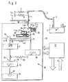
- the parts shown in the frame 18 according to Figure 1 form an actuator or a load adjustment device 10, which are combined in one unit.
- the load adjustment device 10 includes a servomotor or electric motor 14, which is connected to a throttle valve shaft for a throttle valve 9 via a gear (not shown in the drawing for the sake of simplicity).
- the actuating forces of the electric motor 14 are transmitted to the throttle valve 9 via the electric motor 14, and an adjustment to the desired position is thereby brought about.
- the load adjusting device 10 can be adjusted by means of an accelerator pedal 1, whereby by actuating the accelerator pedal 1 a lever 2 is shifted between an idle stop (LL) and a full load stop (VL) and is biased in the idle direction (LL) via a return spring 5 becomes.
- the accelerator pedal 1 is connected to a driver 4 by means of an accelerator cable 3, so that when the accelerator pedal 1 is actuated, the driver 4 is displaced in the direction of the full load stop (VL).
- a return spring 6 is connected to the driver 4 and biases the driver 4 in the idling direction (LL).
- the driver 4 can bias an automatic train 7 of a transmission, not shown. As long as the throttle cable 3 is not acted on, the driver 4 lies against the idling stop (LL max ) assigned to it (see FIG. 1).
- the driver 4 interacts via a spring, in particular a coupling spring 46, with a control element 8a, which corresponds to the throttle valve shaft not shown in the drawing.
- the driver 4 ensures that the control element 8a is brought into abutment against a first stop 75 arranged on the driver 4 if, via a control device 17, an electric motor 14 does not act on the control element 8a in the idling direction (LL min ).
- the driver 4 bears against the idle stop (LL max ) and is held in this position by the return spring 6 as long as the driver does not actuate the accelerator pedal 1. Furthermore, the spring 46 ensures that the control element 8a is pulled against the stop 75 of the driver.
- the load adjustment device has a second control element 8b which is drive-connected to an electric motor 14.
- the second control element 8b has a driver 15, which enables the first control element 8a to be adjusted only in the idling direction (LL min ), that is to say that the electric motor 14 can only reduce the power to the actuator act.
- a tension spring 82 is connected at one end to the control element 8b and is connected at the other end to a fixed point in the housing of the load adjustment device 10.
- the tension spring 82 effects an adjustment of the control element 8b in the direction of the idle position (LL max ) when the actuator is not energized or the Electric motor 14 is switched off.
- the travel of the second control element 8b and thereby also the travel of the first control element 8a is limited by a stop 16 projecting in the direction of the maximum idle position into the travel of the second control element 8b at the level of the position LL max .
- the first control element 8a is limited in the position of the minimum idle position (LL min ) by a second stop 21 projecting into the travel of the first control element 8a.
- the electronic control device 17 which contains conditioning, logic and control circuits, is indicated schematically.
- the control device 17 stores values for vehicle adaptation and processes the digital or digitized values of various input variables, which then regulate the desired position of the throttle valve 9 via an analog part.
- the electronic control device 17 interacts with the actual value detection device 19 for the drive, which belongs to the control elements 8a, 8b, and a setpoint value detection device 65, which is assigned to the driver 4 and determines the respective position of the driver 4.
- a first potentiometer is assigned to the first actual value detection device 19, and a second potentiometer, also not shown in the drawing, is assigned to the target value detection device 65.
- the control device 17 has the task of all input signals, e.g. Speed to be recorded using the potentiometer and compared with each other. If, for example, the vehicle speed deviates from the setpoint, the actuator is activated until the specified speed is reached.
- Speed e.g. Speed to be recorded using the potentiometer and compared with each other. If, for example, the vehicle speed deviates from the setpoint, the actuator is activated until the specified speed is reached.
- the electronic control device 17 also detects signals via an idle contact 68 (FIG. 2), which is activated by the driver 4, when the latter comes to rest against the idle stop (LL max ) assigned to it.
- the electronic control device 17 serves the purpose of building up a safety logic relating to the control of the first and second control elements 8a, 8b. Once the electronic control device 17 or the electric motor 14 does not operate more properly, is moved by the prestressed in the direction of maximum idling position return spring 6, the throttle valve 9 in the idle emergency position (LLmax), which simultaneously corresponds to an idle emergency position.
- regulation can be carried out upwards (LL max ) and downwards (LL min ) over the entire idling range by means of a single actuator. Furthermore, it is possible, by means of the electric motor 14, to ensure a shutdown of the internal combustion engine in the direction of the idle position (LL max ) outside the idling control range in the anti-slip control case (ASR), since the electric motor 14 only acts to reduce the power on the actuator.
- ASR anti-slip control case
- FIG. 2 shows a further exemplary embodiment of a load adjusting device 10 which, in addition to the driver 4, has an adjusting lever 71 on which the first adjustable stop 75 is arranged.
- Another adjustable stop 76 is received in a cylinder 83 of an actuating magnet 84.
- a compression spring 22 is arranged, which can be pretensioned via the actuating magnet 84 and presses the second stop 76 against the actuating lever 71 and thus also against a third stop 77.
- the adjusting lever 71 is adjustably arranged between two drivers 49, 51 arranged at a distance from one another, which form a freewheel hook 47 which is firmly connected to the driver 4.
- the actuating lever 71 is adjusted by means of an emergency running spring 20 and by means of the third stop 77 cooperating therewith against the first driver 49 in the direction of the idling min position, so that the control element 8a via the first adjustable stop 75 is adjusted to the idle emergency position (LL not ).
- the spring 22 is biased more strongly and adjusts the first actuating lever 71 in the direction of full-load operation (VL) via the second adjustable stop 76 against the action of the somewhat weaker emergency running spring 20, the first actuating lever 71 in the freewheel hook 47 against the second driver 51 to the system is coming. If the driver gives gas out of this position, then the adjusting lever 71 does not have to travel through a dead travel, so that when the accelerator pedal 1 is actuated, the throttle valve 9 can be adjusted immediately without delay.
- the setpoint detection device 65 assigned to the first actuating lever 71 recognizes the respective position of the actuating lever 71 and compares this value with an actual value detection device 19 assigned to the throttle valve 9, so that the electric motor is now controlled via the control device 17 to which the measurement data are fed 14 is controlled until the throttle valve 9 has reached the desired position.
- ARS anti-slip control event
- the internal combustion engine is shut down by means of the first electric motor 14, the control device 17 detecting the corresponding disturbance variable, processing it and thereby controlling the electric motor 14 accordingly until it has set the throttle valve 9 to the required value.
- the electric motor 14 can only have a reducing effect on the drive of the throttle valve 9. This increases operational reliability, since it is ensured that, in the ASR rule, it is not possible to regulate the internal combustion engine because the control element 8b cannot turn the throttle valve shaft in the opening direction.
- FIG. 3 shows a third exemplary embodiment, which differs only slightly from the exemplary embodiments illustrated in FIGS. 2 and 3.
- a further actual value detection device 81 is provided for detecting the position of the throttle valve 9, so that the control device 17 can detect both operating states and compare them with the setpoint value, in order thereby to obtain one to ensure even more precise control of the electric motor 14 or to improve the control behavior of the actuator.
- the electric motor 14 can be coupled to the throttle valve shaft via a clutch 80, which is illustrated in FIG. 3 by the control element 8b, so that a drive connection is established between the output shaft 38 of the electric motor 14 and the throttle valve shaft in the idling direction.
- a clutch 80 which is illustrated in FIG. 3 by the control element 8b, so that a drive connection is established between the output shaft 38 of the electric motor 14 and the throttle valve shaft in the idling direction.
Landscapes
- Engineering & Computer Science (AREA)
- Chemical & Material Sciences (AREA)
- Combustion & Propulsion (AREA)
- Mechanical Engineering (AREA)
- General Engineering & Computer Science (AREA)
- Transportation (AREA)
- Control Of Throttle Valves Provided In The Intake System Or In The Exhaust System (AREA)
Applications Claiming Priority (2)
| Application Number | Priority Date | Filing Date | Title |
|---|---|---|---|
| DE4034575 | 1990-10-31 | ||
| DE4034575A DE4034575A1 (de) | 1990-10-31 | 1990-10-31 | Lastverstelleinrichtung |
Publications (2)
| Publication Number | Publication Date |
|---|---|
| EP0483448A1 true EP0483448A1 (fr) | 1992-05-06 |
| EP0483448B1 EP0483448B1 (fr) | 1994-08-03 |
Family
ID=6417348
Family Applications (1)
| Application Number | Title | Priority Date | Filing Date |
|---|---|---|---|
| EP91105822A Expired - Lifetime EP0483448B1 (fr) | 1990-10-31 | 1991-04-12 | Dispositif de réglage de charge |
Country Status (3)
| Country | Link |
|---|---|
| US (1) | US5148790A (fr) |
| EP (1) | EP0483448B1 (fr) |
| DE (2) | DE4034575A1 (fr) |
Families Citing this family (13)
| Publication number | Priority date | Publication date | Assignee | Title |
|---|---|---|---|---|
| US5479908A (en) * | 1994-05-26 | 1996-01-02 | Ingersoll-Rand Company | Engine speed control device |
| DE19519836C5 (de) * | 1995-05-31 | 2010-10-14 | Continental Automotive Gmbh | Lastverstelleinrichtung |
| DE19524941B4 (de) * | 1995-07-08 | 2006-05-18 | Siemens Ag | Lastverstellvorrichtung |
| DE19530317C1 (de) * | 1995-08-17 | 1997-03-06 | Siemens Ag | Verfahren zur Lasteinstellung einer Brennkraftmaschine |
| US6070852A (en) * | 1999-01-29 | 2000-06-06 | Ford Motor Company | Electronic throttle control system |
| US6095488A (en) * | 1999-01-29 | 2000-08-01 | Ford Global Technologies, Inc. | Electronic throttle control with adjustable default mechanism |
| US6155533C1 (en) * | 1999-01-29 | 2002-07-30 | Visteon Global Tech Inc | Default mechanism for electronic throttle control system |
| US6244565B1 (en) | 1999-01-29 | 2001-06-12 | Ford Global Technologies, Inc. | Throttle body shaft axial play control |
| US6299545B1 (en) | 1999-05-03 | 2001-10-09 | Visteon Global Tech., Inc. | Rotating shaft assembly |
| US6173939B1 (en) | 1999-11-10 | 2001-01-16 | Ford Global Technologies, Inc. | Electronic throttle control system with two-spring failsafe mechanism |
| US6253732B1 (en) | 1999-11-11 | 2001-07-03 | Ford Global Technologies, Inc. | Electronic throttle return mechanism with a two-spring and two-lever default mechanism |
| US6267352B1 (en) | 1999-11-11 | 2001-07-31 | Ford Global Technologies, Inc. | Electronic throttle return mechanism with default and gear backlash control |
| US6286481B1 (en) | 1999-11-11 | 2001-09-11 | Ford Global Technologies, Inc. | Electronic throttle return mechanism with a two-spring and one lever default mechanism |
Citations (4)
| Publication number | Priority date | Publication date | Assignee | Title |
|---|---|---|---|---|
| EP0300153A2 (fr) * | 1987-07-23 | 1989-01-25 | VDO Adolf Schindling AG | Dispositif de réglage de charge |
| EP0389649A1 (fr) * | 1989-03-25 | 1990-10-03 | Audi Ag | Papillon d'accélérateur |
| EP0412237A1 (fr) * | 1989-08-10 | 1991-02-13 | Audi Ag | Papillon |
| EP0378737B1 (fr) * | 1989-01-20 | 1993-11-10 | VDO Adolf Schindling AG | Dispositif de réglage de la charge |
Family Cites Families (6)
| Publication number | Priority date | Publication date | Assignee | Title |
|---|---|---|---|---|
| DE3908596C2 (de) * | 1989-03-16 | 1999-11-11 | Bosch Gmbh Robert | Einrichtung zum Übertragen einer Stellposition eines Sollwertgebers |
| DE3927043A1 (de) * | 1989-08-16 | 1991-02-21 | Vdo Schindling | Lastverstelleinrichtung |
| DE3934738A1 (de) * | 1989-10-18 | 1991-04-25 | Bosch Gmbh Robert | Vorrichtung ii mit einem stellmotor zum eingriff in eine uebertragungseinrichtung |
| DE3936875A1 (de) * | 1989-11-06 | 1991-05-08 | Hella Kg Hueck & Co | Drosselklappe fuer eine brennkraftmaschine |
| DE4015423A1 (de) * | 1990-05-14 | 1991-11-21 | Bosch Gmbh Robert | Motorsteuereinrichtung |
| US5076232A (en) * | 1990-09-14 | 1991-12-31 | Vdo Adolf Schindling Ag | Load adjustment device |
-
1990
- 1990-10-31 DE DE4034575A patent/DE4034575A1/de not_active Withdrawn
-
1991
- 1991-04-12 EP EP91105822A patent/EP0483448B1/fr not_active Expired - Lifetime
- 1991-04-12 DE DE59102428T patent/DE59102428D1/de not_active Expired - Fee Related
- 1991-10-23 US US07/781,753 patent/US5148790A/en not_active Expired - Lifetime
Patent Citations (4)
| Publication number | Priority date | Publication date | Assignee | Title |
|---|---|---|---|---|
| EP0300153A2 (fr) * | 1987-07-23 | 1989-01-25 | VDO Adolf Schindling AG | Dispositif de réglage de charge |
| EP0378737B1 (fr) * | 1989-01-20 | 1993-11-10 | VDO Adolf Schindling AG | Dispositif de réglage de la charge |
| EP0389649A1 (fr) * | 1989-03-25 | 1990-10-03 | Audi Ag | Papillon d'accélérateur |
| EP0412237A1 (fr) * | 1989-08-10 | 1991-02-13 | Audi Ag | Papillon |
Also Published As
| Publication number | Publication date |
|---|---|
| DE59102428D1 (de) | 1994-09-08 |
| DE4034575A1 (de) | 1992-05-07 |
| US5148790A (en) | 1992-09-22 |
| EP0483448B1 (fr) | 1994-08-03 |
Similar Documents
| Publication | Publication Date | Title |
|---|---|---|
| DE4313993C2 (de) | Leistungsübertragungs-Steuervorrichtung für ein Fahrzeug mit einem Verbrennungsmotor | |
| EP0413081A1 (fr) | Dispositif de réglage de charge | |
| DE69103002T2 (de) | Drosselklappe. | |
| EP0413082A1 (fr) | Dispositif de réglage de charge | |
| EP0483448A1 (fr) | Dispositif de réglage de charge | |
| EP0412237B1 (fr) | Papillon | |
| EP0123731B1 (fr) | Dispositif pour transmettre la position d'un élément de commande | |
| EP0269780B1 (fr) | Dispositif de transmission de la position d'un élément de commande actionnable par le conducteur d'un véhicule | |
| DE4036566A1 (de) | Vorrichtung zur steuerung und/oder regelung einer betriebsgroesse einer brennkraftmaschine | |
| EP0378737B1 (fr) | Dispositif de réglage de la charge | |
| EP0378736B1 (fr) | Dispositif de réglage de la charge | |
| EP0456904B1 (fr) | Dispositif de réglage de la puissance | |
| DE3628538C2 (de) | Anordnung für ein Kraftfahrzeug zum Eingriff in die Verbindung zwischen einem Bedienorgan und einem die Leistung der Brennkraftmaschine des Kraftfahrzeugs bestimmenden Steuerorgan | |
| EP0523432A2 (fr) | Dispositif de positionnement du papillon d'un moteur à combustion | |
| EP0106011A2 (fr) | Commande de vitesse électrique | |
| EP0306641A1 (fr) | Commande électrique de papillon pour moteur à combustion interne | |
| EP0525376A1 (fr) | Dispositif de commande en fonction de la charge pour un moteur | |
| DE69712365T2 (de) | Modesteurung für eine brennkraftmaschine mit magermischverbrennung | |
| EP0482284A1 (fr) | Dispositif de réglage de charge | |
| EP0478884B1 (fr) | Dispositif de réglage de charge | |
| EP0540811B1 (fr) | Dispositif pour le positionnement d'un clapet d'étranglement | |
| EP0455882A2 (fr) | Dispositif de réglage pour un papillon des gaz | |
| EP0421047A1 (fr) | Dispositif de réglage de charge | |
| EP0455883B1 (fr) | Dispositif de réglage pour un papillon des gaz | |
| EP0390961A1 (fr) | Dispositif de positionnement d'un organe d'étranglement |
Legal Events
| Date | Code | Title | Description |
|---|---|---|---|
| PUAI | Public reference made under article 153(3) epc to a published international application that has entered the european phase |
Free format text: ORIGINAL CODE: 0009012 |
|
| 17P | Request for examination filed |
Effective date: 19920124 |
|
| AK | Designated contracting states |
Kind code of ref document: A1 Designated state(s): DE ES FR GB IT SE |
|
| 17Q | First examination report despatched |
Effective date: 19930203 |
|
| GRAA | (expected) grant |
Free format text: ORIGINAL CODE: 0009210 |
|
| AK | Designated contracting states |
Kind code of ref document: B1 Designated state(s): DE ES FR GB IT SE |
|
| PG25 | Lapsed in a contracting state [announced via postgrant information from national office to epo] |
Ref country code: IT Free format text: LAPSE BECAUSE OF FAILURE TO SUBMIT A TRANSLATION OF THE DESCRIPTION OR TO PAY THE FEE WITHIN THE PRE;WARNING: LAPSES OF ITALIAN PATENTS WITH EFFECTIVE DATE BEFORE 2007 MAY HAVE OCCURRED AT ANY TIME BEFORE 2007. THE CORRECT EFFECTIVE DATE MAY BE DIFFERENT FROM THE ONE RECORDED.SCRIBED TIME-LIMIT Effective date: 19940803 Ref country code: GB Effective date: 19940803 Ref country code: ES Free format text: THE PATENT HAS BEEN ANNULLED BY A DECISION OF A NATIONAL AUTHORITY Effective date: 19940803 |
|
| ET | Fr: translation filed | ||
| REF | Corresponds to: |
Ref document number: 59102428 Country of ref document: DE Date of ref document: 19940908 |
|
| PG25 | Lapsed in a contracting state [announced via postgrant information from national office to epo] |
Ref country code: SE Effective date: 19941103 |
|
| GBV | Gb: ep patent (uk) treated as always having been void in accordance with gb section 77(7)/1977 [no translation filed] |
Effective date: 19940803 |
|
| PLBE | No opposition filed within time limit |
Free format text: ORIGINAL CODE: 0009261 |
|
| STAA | Information on the status of an ep patent application or granted ep patent |
Free format text: STATUS: NO OPPOSITION FILED WITHIN TIME LIMIT |
|
| 26N | No opposition filed | ||
| PGFP | Annual fee paid to national office [announced via postgrant information from national office to epo] |
Ref country code: DE Payment date: 19970320 Year of fee payment: 7 |
|
| PGFP | Annual fee paid to national office [announced via postgrant information from national office to epo] |
Ref country code: FR Payment date: 19980313 Year of fee payment: 8 |
|
| PG25 | Lapsed in a contracting state [announced via postgrant information from national office to epo] |
Ref country code: DE Free format text: LAPSE BECAUSE OF NON-PAYMENT OF DUE FEES Effective date: 19990202 |
|
| PG25 | Lapsed in a contracting state [announced via postgrant information from national office to epo] |
Ref country code: FR Free format text: LAPSE BECAUSE OF NON-PAYMENT OF DUE FEES Effective date: 19991231 |
|
| REG | Reference to a national code |
Ref country code: FR Ref legal event code: ST |