EP0483391B1 - Vérification automatique de signatures - Google Patents
Vérification automatique de signatures Download PDFInfo
- Publication number
- EP0483391B1 EP0483391B1 EP90120620A EP90120620A EP0483391B1 EP 0483391 B1 EP0483391 B1 EP 0483391B1 EP 90120620 A EP90120620 A EP 90120620A EP 90120620 A EP90120620 A EP 90120620A EP 0483391 B1 EP0483391 B1 EP 0483391B1
- Authority
- EP
- European Patent Office
- Prior art keywords
- signature
- determining
- gravity
- image
- grey scale
- Prior art date
- Legal status (The legal status is an assumption and is not a legal conclusion. Google has not performed a legal analysis and makes no representation as to the accuracy of the status listed.)
- Expired - Lifetime
Links
Images


Classifications
-
- G—PHYSICS
- G06—COMPUTING; CALCULATING OR COUNTING
- G06V—IMAGE OR VIDEO RECOGNITION OR UNDERSTANDING
- G06V40/00—Recognition of biometric, human-related or animal-related patterns in image or video data
- G06V40/30—Writer recognition; Reading and verifying signatures
-
- G—PHYSICS
- G07—CHECKING-DEVICES
- G07C—TIME OR ATTENDANCE REGISTERS; REGISTERING OR INDICATING THE WORKING OF MACHINES; GENERATING RANDOM NUMBERS; VOTING OR LOTTERY APPARATUS; ARRANGEMENTS, SYSTEMS OR APPARATUS FOR CHECKING NOT PROVIDED FOR ELSEWHERE
- G07C9/00—Individual registration on entry or exit
- G07C9/30—Individual registration on entry or exit not involving the use of a pass
- G07C9/32—Individual registration on entry or exit not involving the use of a pass in combination with an identity check
- G07C9/35—Individual registration on entry or exit not involving the use of a pass in combination with an identity check by means of a handwritten signature
Definitions
- the invention relates to a method of automatically verifying a signature of an individual and an apparatus for carrying out this method.
- Signature verification is known for example from US-A-4,495,644 (GB-A-2 104 698) in which a transducer pad is used for capturing the signature.
- the pressure caused by the individual's pen when signing on this transducer pad produces an analogue voltage which is converted to digital form.
- the digital values are processed under the control of a microprocessor to determine numerical parameter values each representing a significant feature of the signature. Examples of parameters are "Pen out of or in contact with paper”, “Current and previous position of pen”, “Pen down, pen up”, “Length of signature", “Duration of signature", etc.
- the parameter values of a signature to be verified are then compared with the parameter values of a reference signature which were calculated and stored earlier.
- the features are measured for a real signature by a process involving automatic thresholding, to extract the signature from the background; analysis of projections, to segment the signature into vertical zones and identification of the tall letters with respect to the spelling of the signature.
- Statistical assumptions are made regarding the expected variation in feature values among different writers and for a single writer.
- US-A-4,286,255 discloses a method and apparatus for determining whether a newly-signed signature and a previously recorded signature were made by the same person.
- the method includes the steps for scanning a document containing the newly signed signature to provide an electrical signal representative of the reflectivity of the newly signed signature and the document and generating a signature envelope from the electrical signal with the envelope being formed of selected points on the signature.
- a plurality of characteristics of the newly signed signature are then calculated based on the location and magnitude of the selected points forming the signature envelope with respect to a reference line.
- the calculated characteristics of the newly signed signature are then compared with corresponding characteristics of a standard signature domed from a group of previously recorded signatures and a signature verification decision is generated on the degree with the compared characteristics match.
- US-A-4,028,674 discloses a signature verification where an image mosaic for a signature to be verified is stored in a memory and wherein a prototype feature set for said signature is stored in memory. Binary signals representative of the location and magnitude of positive and negative peaks in mosaic and stroke character in the region of each of said peak are generated. A two dimensional feature set patterned after the prototype set is stored with the signals ordered in dependence upon the occurrence of the peaks in the signature and accompanied by peak rank in terms of peak magnitude and stroke characteristic in the vicinity of each peak. The feature vector set is then compared with the prototype vector set and identity is signaled when within predetermined limits the feature set matches the prototype set.
- the described system cannot be used in connection with signatures which were not written on this mechanical sensor. This has the consequence that the known system cannot verify signatures on cheques or the like which were signed away from the computer for example at home.
- the parameters which can be calculated from the captured signature are not very expressive. For that reason, a lot of parameters are necessary to reach a high reliability for the TRUE/FALSE-decision and, as a consequence, the processor time and the need for storage is high.
- An object of the invention is to provide a signature verification system which is able to verify any signature irrespective of where or when it was written.
- Another object of the invention is to provide a signature verification system with increased reliability but with decreased processor requirements.
- the signature verification system according to the invention is independent of a transducer pad or the like. For that reason, the system is able to verify a signature on a cheque which was signed for example at home.
- an image of a signature contains much more information than the captured values of a transducer pad. For example, the resolution of an image with regard to the size of a single picture element and with regard to the possible greyscale-values of the picture elements cannot be deduced from a transducer pad. Further, the number of picture elements of the image is usually very high. Finally, the image contains the signature including its surrounding whereas a transducer pad only creates values of the signature. As a result, the signature verification system according to the invention is able to reach a higher reliability with lower processor requirements.
- the digitized image is established by scanning the signature and digitizing the obtained values.
- the use of a scanner is a very effective possibility to produce an image with a high number of picture elements and a high resolution.
- the digital image can then be aligned with respect to the angle of the signature and can be normalized with respect to the size of the signature.
- the size of the raster of the image can be reduced. All these measures can be used one after the other or alternatively.
- Significant parameters can be derived from the position of the center-of-gravity of the greyscale-values of the picture elements of a respective column or of a respective row.
- a parameter with a high reliability for a TRUE/FALSE-decision is the position of the center-of-gravity of the greysclae-values of all picture elements of the image.
- a further advantage of the above mentioned signature verification system is that the calculation of the significant parameters represents at the same time an encryption of the signature. Furthermore, the calculation of these parameters provides a tremendous compression of the signature related data. No further compression is needed. This has the consequence that less storage for storing the significant parameters of a signature is necessary and, due to that, the processing time is decreased.
- a signature input (10) is the first step of a signature verification system.
- the signature input (10) is performed by a scanner or the like and establishes a digitized image of a signature as will be described in connection with Fig. 3.
- the digitized image of the signature contains a number of picture elements (pixels) which form a three dimensional information space.
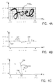
- An image of the signature "Joel" is shown in Fig. 4a where the picture elements of the image form a two dimensional array and where the blackness of the picture elements is the third dimension.
- the blackness of every picture element is represented by two values (one bit: white or black) or more than two values, for example 256 values (8 bits: white or black or 254 greyscale-values between white and black). These values of the blackness of a picture element (greyscale-values) will be subsequently used as the density of the picture element.
- the digitized image of the signature is transferred from the scanner and stored in a computer system for further processing.
- a mode (12) After signature input (10) the next step is to select a mode (12).
- Two modes are possible: a reference signature analysis mode (left side of Fig. 1) and a signature verification mode (right side of Fig. 1). Both, the reference signature analysis mode and the signature verification mode, are performed by the above mentioned computer system by processing digitized images of signatures.
- the reference signature analysis mode one or more reference signatures of an individual are processed for storing sets of reference parameter values. This mode provides the basis for future verifications. In this mode it has to be ensured that the processed signature is the true signature of the individual. No comparisons or verifications are done usually in this mode.
- all sets of reference parameter values are calculated (20') in a first step. Then, in a further step, all calculated sets of reference parameter values are stored (27) in a memory of the computer system.
- one present signature of an individual is processed for creating sets of parameter values to be verified.
- the present signature is true or false with regard to the corresponding reference signature, or in other words if the individual who has written the present signature is identical with the individual who has written the reference signature.
- one set of parameter values to be verified is calculated (20) in a first step.
- This set of parameter values to be verified is compared (22) with the stored corresponding set of reference parameter values.
- the next step is a verification step (23) in which it is decided if the sets of parameter values to be verified match within given tolerances with the sets of reference parameter values.
- various statistical methods are used to evaluate if the signature to be verified is true or false.
- These calculated statistical values are then used as probability values of correspondence of the set of reference parameter values and the corresponding set of parameter values to be verified. For example, if the probability value of correspondence is 100%, then there is no deviation between the set of reference parameter values and the set of parameter values to be verified, however, if the probability value of correspondence is 0%, then there is no correspondence at all between these two sets of parameter values.
- weighting factors can depend on the kind of parameter to which they are assigned or on the individual who is the originator of the signature or on both.
- the abscissa carries the parameter-number and the ordinate the accumulated probability values.
- the diagram is divided into three parts: a confidence band (30), a TRUE-area (32) and a FALSE-area (33).
- the set of parameter values to be verified of a first parameter is calculated and compared with the corresponding set of reference parameter values. Then, depending on the comparison and as described above, a probability value of correspondence is evaluated.
- This probability value (35) is shown in Fig. 2 at parameter-number 1. Its value is 75% for example and its position is within the confidence band (30).
- the set of parameter values to be verified of a second parameter is calculated and compared with the corresponding set of reference parameter values. A probability value relating to this second parameter is evaluated and added to the probability value related to the first parameter.
- This accumulated probability value (37) is shown in Fig. 2 at parameter-number 2. As the probability value relating to the second parameter is 25%, the accumulated probability value is 100% and its position is still within the confidence band (30).
- sequence of the sets of parameter values which are calculated and compared one after the other depends primarily on the application in which the signature verification system is used. Furthermore, the sequence may be selected depending on e.g. the expressiveness of the respective parameters. In general, the sequence is selected in the aspect of a best compromise in short calculation-time, low data-rate and high reliability of the signature verification system.
- the signature input (10) is performed with a scanner or the like. This is done in a signature scanning step (101). In a following step (102) the scanned image is digitized.
- a next step (103) the digitized image is cleaned up. This means that all small points or dots which have been scanned and digitized due to dirt or other particles in the surroundings of the signature are eliminated in the digital image for example by bringing the picture elements in question into line with the picture elements in the neighborhood.
- This cleaning up step (103) restricts the digital image exactly to the signature and prevents the possibility of a faulty calculation of reference parameter values or parameter values to be verified.
- the angle of the signature is aligned with respect to a given axis, for example with respect to a x- and a y-coordinate.
- This alignment step (104) is followed by a normalization step (105) in which the size of the picture elements, respectively, is enlarged until the signature fills up a given size of the two dimensional array of the digital image.
- a normalization step (105) in which the size of the picture elements, respectively, is enlarged until the signature fills up a given size of the two dimensional array of the digital image.
- the signature has been aligned and the picture elements have been enlarged so that the signature (“Joel") fills up the size of the whole array.
- the signature input (10) includes a raster reduction step (106) in which the signature is scaled down by combining adjacent picture elements and thus decreasing the number of scaled down picture elements which represent the signature.
- the size of the signature in the array remains the same.
- the raster of the two dimensional array could be reduced to 20 scaled down picture elements in the direction of the x-coordinate and 10 scaled down picture elements in the y-coordinate.
- cleaning up step (103), the alignment step (104), the normalization step (105) and the raster reduction step (106) are optional.
- the same step or steps must be used in connection with the calculation of correspondent parameter values to be verified as well.
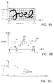
- a first possibility of significant parameters which can be used in the calculating steps (20, 20') are the positions of the centers-of-gravity of the densities per column or per row and other related parameters which will be described now in connection with Figs. 4a to 4c.
- the digital image of the signature contains a number of picture elements (pixels).
- the picture elements are much smaller than are shown in Fig. 4a. Every picture element has one out of 256 values which cover a range from black to white with all greyscale-values inbetween. This greyscale-value of a picture element is the density of the respective picture element.
- the positions of the centers-of-gravity of all densities per column or per row are calculated as follows. If the density of the picture element (i,j) is densij and if the center-of-gravity of all densities of the column (i) is gravxi, then the following equation is defined:
- gravity lines (234, 235) for the columns and for the rows can be calculated depending on the positions (231, 232) of the centers-of-gravity of the densities per column and per row.
- positions (231, 232) of the centers-of-gravity of the densities per column and per row can be calculated.
- other ways of calculating these gravity lines (234, 235) can also be used.
- the values of A, B, C and D can be used as sets of parameter values of the signature "Joel".
- the position of a gravity-center (237, 238) can be calculated.
- the y-coordinate cy (237) of the-gravity center is the mean value of all positions (231) of the centers-of-gravity of the columns.
- the x-coordinate cx (238) is the mean value of all positions (232) of the centers-of-gravity of the rows.
- the position of the gravity-center (237, 238) can be calculated as follows:
- cy and cx can be used as a set of parameter values of the signature "Joel”.
- the position of the gravity-center (237, 238) is a very expressive parameter. For that reason, this position can be used as the first parameter (parameter-number 1) to be selected in the calculating step (20) of the signature verification mode.
- a second possibility of significant parameters which can be used in the calculating steps (20, 20') are the positions of the maximum values of the densities per column or per row and other related parameters which will be described now in connection with Figs. 5a to 5c.
- Fig. 5a corresponds to Fig. 4a and its accompanying description above.
- the positions of the maximum values of the densities per column or per row are calculated as follows. If the density of the picture element (i,j) is densij and if the maximum value of all densities of the column (i) is maxxi, the following equation is defined:
- maximum lines (244, 245) for the columns and for the rows can be calculated depending on the positions (241, 242) of the maximum values of the densities per column and per row.
- maximum lines (244, 245) can also be used.
- E, F, G and H can be used as sets of parameter values of the signature "Joel".
- a third possibility of significant parameters which can be used in the calculating steps (20, 20') are sum values of the densities per column or per row and other related parameters which will be described now in connection with Figs. 6a to 6c.
- Fig. 6a corresponds to Fig. 4a and its accompanying description above.
- Figs. 6b and 6c Unlike Figs. 4b, 4c, 5b and 5c, where both coordinates relate to position-values, one coordinate of Figs. 6b and 6c does not relate to position-values but to sum values of densities.
- the sum values of the densities per column or per row are calculated as follows. If the density of the picture element (i,j) is densij and if the sum value of all densities of the column (i) is sumxi, then the following equation is defined:
- Another significant parameter of the signature "Joel" is the number how often one of the sum values of the densities per column is greater than a given offset sum. This number is called the x-sum number.
- the offset sum is denoted with the reference sign (254) and the x-sum number is 2.
- the x-sum number and the x-sum positions can be used as further sets of parameter values of the signature "Joel”.
- Figs. 7a to 7c show a signature, its line-width and its envelope.
- Fig. 7a corresponds to Fig. 4a and its accompanying description above.
- Fig. 7b shows a part of the two dimensional array of Fig. 7a in an increased size. This part contains a line-section of the signature "Joel".
- the correlation between Figs. 7a and 7b is indicated by the arrow which points from Fig. 7a to Fig. 7b.
- the edges of the line-section are denoted with the reference sign (261).
- the line-section of the signature shown in Fig. 7b is surrounded by a rectangle (263).
- Fig. 7c shows a diagram which corresponds to the columns in the rectangle (263) of the array of Fig. 7b. Unlike Figs. 4b, 4c, 5b and 5c, where both coordinates relate to position-values, one coordinate of Fig. 7c does not relate to position-values but to sum values of densities.
- Fig. 7c the sum values (265) of all densities per column are entered for all columns of the rectangle (263). If these sum values (265) are connected by lines, the originating curve has two turning points (267, 268). The distance between the two turning points in the direction of the x-coordinate corresponds to the line width (276) of the signature.
- This value of the line-width (276) can be used as a set of parameter values of the signature "Joel”.
- the reference signs (271, 272, 273 and 274) in Fig. 7a characterize those positions of the signature which have an extreme value in one of the four orthogonal directions of the two dimensional array.
- the position (272) has the greatest value in the direction of the x-coordinate.
- These extreme values form an envelope of the signature when lines are drawn through them which are parallel to the x- and the y-coordinate.
- the values (271, 272, 273 and 274) of this envelope can be used as a set of parameter values of the signature "Joel".
- Figs. 8a to 8c show a signature, one of its bows and the segmentation of this bow.
- Fig. 8a corresponds to Fig. 4a and its accompanying description above.
- Fig. 8b shows a part of the two dimensional array of Fig. 8a in an increased size. This part contains a bow-section of the signature "Joel".
- the correlation between Figs. 8a and 8b is indicated by the arrow which points from Fig. 8a to Fig. 8b.
- the edges of the bow-section are denoted with the reference sign (281).
- the bow-section of the signature shown in Fig. 8b is surrounded by a rectangle (283).
- Fig. 8c shows a diagram which corresponds to the columns in the rectangle (283) of the array of Fig. 8b. Unlike Figs. 4b, 4c, 5b and 5c, where both coordinates relate to position-values, one coordinate of Fig. 8c does not relate to position-values but to sum values of densities.
- Fig. 8c the sum values (285) of all densities per column are entered for all columns of the rectangle (283). If these sum values (285) are connected by lines, the originating curve has two extreme points (287, 288) which define ending points (292, 293) of a segment (290) of the bow as shown in Fig. 8b. The correlation between the extreme points (287, 288) and these ending points (292, 293) is indicated by the two arrows which point from Fig. 8c to Fig. 8b.
- This polynomial forms a parabola.
- Another way to describe a second order polynomial is to pick out three points of the parabola: x1, y1; x2, y2; x3, y3. Having these three points, it is possible to calculate the values of a, b and c of the above mentioned equation of the polynomial.
- the first and the second point of the parabola are the two ending points (292, 293) of the bow-segment shown in Fig. 8b.
- the third point (x3, y3) is calculated depending on all other points of the bow segment (290) shown in Fig. 8b.
- This third point (x3, y3) is calculated in such a way that the parabola which corresponds to the calculated second order polynomial matches with the bow-segment (290) shown in Fig. 8b in as many points as possible.
- the methods of parabola regression are used, especially the method of Gauss and/or the method of Cramer.
- the whole signature is divided or cut into a number of segments which represent unique pieces of the signature. Then all these segments are analyzed and replaced by the two ending points of the segments and one calculated third point, respectively, as it is described above.
- the respective three points of all segments can be used as sets of parameter values of the signature "Joel”.
- all these significant parameters in the calculating step (20, 20') is optional. It is possible to use all parameters or only some distinct ones. It is also possible to calculate all sets of reference parameter values, but to calculate only some of the corresponding sets of parameter values to be verified. In this case, only the calculated sets of parameter values to be verified are compared with the corresponding sets of reference parameter values.
- a preselection means that in the signature verification mode the selected parameter for preselection is the first parameter to be calculated (20) and compared (22). Then, the verification step (23) is carried out and if this step carries out a FALSE-decision then the signature to be verified is rejected at once. If the verification step (23) carries out a TRUE-decision then the procedure is continued with the calculations as already described. By that, processing time can be saved.
- the described image verification system can especially be used in banking systems where all sets of reference parameter values of the reference signature are stored in a central computing system and where decentralized computers in banks at different places calculate the sets of parameter values to be verified out of a present signature, receive the corresponding sets of parameter values via a connecting line from the central computing system and then compare the sets of parameter values to be verified with the sets of reference parameter values and accept or reject the present signature to be verified.
- the whole signature verification system works automatically without any intervention of a human being. Furthermore, the system works very fast and is very flexible for adaption for example to different banking systems.
- the described system can be used in connection with text analysis or character recognition and in connection with computer implemented manufacturing.
- the characters of the alphabet and in the other case, the parts to be manufactured correspond to the reference signatures.
- the significant parameters of the characters or of the parts to be manufactured are calculated and stored and then compared with the characters or parts to be verified.
Landscapes
- Engineering & Computer Science (AREA)
- Physics & Mathematics (AREA)
- General Physics & Mathematics (AREA)
- Human Computer Interaction (AREA)
- Multimedia (AREA)
- Theoretical Computer Science (AREA)
- Collating Specific Patterns (AREA)
Claims (7)
- Procédé pour vérifier automatiquement une signature d'une personne sur un chèque ou autre document avec un système informatique, ledit procédé comprenant les étapes consistant à :dans lequel l'étape consistant à déterminer au moins un paramètre significatif est caractérisé parmémoriser dans une mémoire une ou plusieurs références définissant une ou plusieurs caractéristiques respectives d'une signature valide de ladite personne ;numériser une image de la signature à vérifier, l'image numérisée représentant des niveaux d'échelle de gris d'une multiplicité de pixels ;déterminer au moins un paramètre significatif de ladite image numérisée ; comparer lesdits paramètres significatifs à la référence mémorisée correspondante ;déterminer la validité de la signature à vérifier basée sur l'étape de comparaison ; etsi ladite signature est déterminée être invalide, rejeter ledit chèque ou autre document, etsi ladite signature est déterminée être valide, accepter ledit chèque ou autre document,déterminer un centre d'une ligne de gravité (gravx, 234, gravx 235) dans une direction (x, y) pour l'image numérisée en déterminant une pluralité de centres de gravité (gravxi, 231, gravxi, 232) des pixels perpendiculaires à ladite direction (x, y) à des emplacements respectifs espacés (x = 1, ..., n ; y = 1, ..., m) dans ladite direction en utilisant les niveaux d'échelle de gris (densiJ) comme facteur de pondération pour les pixels respectifs (i, J) et déterminer ensuite ledit centre de la ligne de gravité basé sur ladite pluralité de centres de gravités ;et/oudéterminer les positions des pixels ayant une valeur d'échelle de gris maximale (maxxi, maxyJ) pour chacune d'une pluralité de lignes parallèles à travers ladite image ;et/oudéterminer les sommes (sommexi, sommeyJ) des niveaux d'échelle de gris (densiJ) pour les pixels dans chacune d'une pluralité de lignes parallèles à travers ladite image.
- Procédé selon la revendication 1, dans lequel ledit centre de la ligne de gravité est déterminé par régression linéaire de ladite pluralité de centres de gravité.
- Procédé selon la revendication 1 ou 2, dans lequel l'étape consistant à déterminer une ligne du centre de gravité comprend l'étape consistant à déterminer chacun desdits centres de gravité basés sur un pixel le long d'une ligne perpendiculaire à ladite direction et passant à travers un emplacement espacé respectif, ledit pixel ayant un niveau d'échelle de gris maximal le long de ladite ligne.
- Procédé selon la revendication 1 à 3, dans lequel l'étape de détermination de la position comprend l'étape consistant à calculer lesdites valeurs d'échelle de gris maximales pour chaque colonne ou rangée de l'image numérisée.
- Procédé selon la revendication 1 à 4, dans lequel seules les sommes qui dépassent un seuil sont comparées à la référence correspondante.
- Système d'ordinateur pour vérifier une signature d'une personne sur un chèque ou autre document, ledit système d'ordinateur comprenant :dans lequel ledit moyen pour déterminer ledit au moins un paramètre significatif est caractérisé parun moyen pour mémoriser une ou plusieurs références définissant une ou plusieurs caractéristiques respectives pour une signature valide de ladite personne ;un moyen pour numériser une image de la signature à vérifier, l'image numérisée représentant les niveaux d'échelle de gris d'une multiplicité de pixels ;un moyen pour déterminer au moins un paramètre significatif de ladite image numérisée ;un moyen pour comparer ledit paramètres significatif à la référence mémorisée correspondante ;un moyen pour comparer ledit paramètre ou lesdits paramètres significatif(s) à la référence ou aux références correspondante(s) pour la signature valide afin de déterminer si ladite signature est valide, etsi ladite signature est déterminée être invalide, rejeter ledit chèque ou autre document, etsi ladite signature est déterminée être valide, accepter ledit chèque ou autre document ;un moyen pour déterminer un centre d'une ligne de gravité (gravx, 234 ; gravx ; 235) dans une direction (x, y) pour l'image numérisée en déterminant une pluralité de centres de gravité (gravxi, 231 ; gravxi, 232) des pixels perpendiculaires à ladite direction à des emplacements espacés respectifs (x = 1, ..., n ; y = 1, ..., m) dans ladite direction en utilisant les niveaux d'échelle de gris (densiJ) comme facteur de pondération pour les pixels respectifs (i, J) et déterminer ensuite ledit centre de la ligne de gravité basé sur ladite pluralité de centres de gravités ;et/ouun moyen pour déterminer les positions des pixels ayant une valeur d'échelle de gris maximale (maxxi, maxyJ) pour chacune d'une pluralité de lignes parallèles à travers ladite image ;et/ouun moyen pour déterminer les sommes (sommexi, sommeyJ) des niveaux d'échelle de gris (densiJ) pour les pixels dans chacune d'une pluralité de lignes parallèles à travers ladite image.
- Système d'ordinateur selon la revendication 6, dans lequel le moyen de détermination détermine la valeur d'échelle de gris maximale pour chaque colonne et rangée de l'image numérisée.
Priority Applications (4)
| Application Number | Priority Date | Filing Date | Title |
|---|---|---|---|
| DE69032542T DE69032542T2 (de) | 1990-10-27 | 1990-10-27 | Automatische Unterschriftsprüfung |
| EP90120620A EP0483391B1 (fr) | 1990-10-27 | 1990-10-27 | Vérification automatique de signatures |
| JP3202822A JPH0823890B2 (ja) | 1990-10-27 | 1991-08-13 | 署名を自動検証する方法と装置 |
| US07/783,450 US5251265A (en) | 1990-10-27 | 1991-10-25 | Automatic signature verification |
Applications Claiming Priority (1)
| Application Number | Priority Date | Filing Date | Title |
|---|---|---|---|
| EP90120620A EP0483391B1 (fr) | 1990-10-27 | 1990-10-27 | Vérification automatique de signatures |
Publications (2)
| Publication Number | Publication Date |
|---|---|
| EP0483391A1 EP0483391A1 (fr) | 1992-05-06 |
| EP0483391B1 true EP0483391B1 (fr) | 1998-08-05 |
Family
ID=8204660
Family Applications (1)
| Application Number | Title | Priority Date | Filing Date |
|---|---|---|---|
| EP90120620A Expired - Lifetime EP0483391B1 (fr) | 1990-10-27 | 1990-10-27 | Vérification automatique de signatures |
Country Status (4)
| Country | Link |
|---|---|
| US (1) | US5251265A (fr) |
| EP (1) | EP0483391B1 (fr) |
| JP (1) | JPH0823890B2 (fr) |
| DE (1) | DE69032542T2 (fr) |
Families Citing this family (46)
| Publication number | Priority date | Publication date | Assignee | Title |
|---|---|---|---|---|
| US5355411A (en) * | 1990-08-14 | 1994-10-11 | Macdonald John L | Document security system |
| US5559895A (en) * | 1991-11-08 | 1996-09-24 | Cornell Research Foundation, Inc. | Adaptive method and system for real time verification of dynamic human signatures |
| US5448375A (en) * | 1992-03-20 | 1995-09-05 | Xerox Corporation | Method and system for labeling a document for storage, manipulation, and retrieval |
| EP0612035B1 (fr) * | 1993-02-19 | 2002-01-30 | International Business Machines Corporation | Réseau neuronal pour la comparaison des traites des formes des images |
| EP0632402B1 (fr) * | 1993-06-30 | 2000-09-06 | International Business Machines Corporation | Méthode de segmentation d'images et classification d'éléments d'image pour traitement de documents |
| JPH0778251A (ja) * | 1993-07-22 | 1995-03-20 | Xerox Corp | ソースベリファイ方法 |
| US5600733A (en) * | 1993-11-01 | 1997-02-04 | Kulicke And Soffa Investments, Inc | Method for locating eye points on objects subject to size variations |
| JPH09506730A (ja) | 1993-12-17 | 1997-06-30 | クインテット、インコーポレイテッド | 自動署名検証の方法 |
| US5614944A (en) * | 1994-03-30 | 1997-03-25 | Nec Corporation | Test method and apparatus of sequentially executing synchronous signal test, dot level test, and gradation test of a video signal generator |
| GB9409773D0 (en) * | 1994-05-13 | 1994-07-06 | Atomic Energy Authority Uk | Identification system |
| US6091835A (en) * | 1994-08-31 | 2000-07-18 | Penop Limited | Method and system for transcribing electronic affirmations |
| US5544255A (en) * | 1994-08-31 | 1996-08-06 | Peripheral Vision Limited | Method and system for the capture, storage, transport and authentication of handwritten signatures |
| GB2307085B (en) * | 1994-09-09 | 1998-09-23 | Motorola Inc | Method and system for recognizing a boundary between characters in handwritten text |
| CA2176406A1 (fr) | 1995-05-25 | 1996-11-26 | John Stewart Denker | Saisie et utilisation d'une caracteristique d'identification personnelle a un terminal de service |
| US5982931A (en) * | 1995-06-07 | 1999-11-09 | Ishimaru; Mikio | Apparatus and method for the manipulation of image containing documents |
| US5745592A (en) * | 1995-07-27 | 1998-04-28 | Lucent Technologies Inc. | Method for detecting forgery in a traced signature by measuring an amount of jitter |
| US5956409A (en) | 1996-04-29 | 1999-09-21 | Quintet, Inc. | Secure application of seals |
| AU9676298A (en) * | 1997-10-01 | 1999-04-23 | Island Graphics Corporation | Image comparing system |
| IL122229A (en) * | 1997-11-17 | 2001-04-30 | Seal Systems Ltd | True-life electronic signatures |
| US6226407B1 (en) * | 1998-03-18 | 2001-05-01 | Microsoft Corporation | Method and apparatus for analyzing computer screens |
| US6757424B2 (en) | 1998-06-29 | 2004-06-29 | Lumeniq, Inc. | Method for conducting analysis of two-dimensional images |
| US7006685B2 (en) * | 1998-06-29 | 2006-02-28 | Lumeniq, Inc. | Method for conducting analysis of two-dimensional images |
| US20020176619A1 (en) * | 1998-06-29 | 2002-11-28 | Love Patrick B. | Systems and methods for analyzing two-dimensional images |
| US6445820B1 (en) * | 1998-06-29 | 2002-09-03 | Limbic Systems, Inc. | Method for conducting analysis of handwriting |
| US6587577B1 (en) * | 1999-04-21 | 2003-07-01 | International Business Machines Corporation | On-line signature verification |
| US7068829B1 (en) | 1999-06-22 | 2006-06-27 | Lumeniq, Inc. | Method and apparatus for imaging samples |
| JP2001125846A (ja) * | 1999-10-26 | 2001-05-11 | Fujitsu Ltd | 電子装置及び記憶媒体 |
| US6424728B1 (en) * | 1999-12-02 | 2002-07-23 | Maan Ammar | Method and apparatus for verification of signatures |
| US6711554B1 (en) * | 1999-12-30 | 2004-03-23 | Lee Salzmann | Method and system for managing and preparing documentation for real estate transactions |
| CA2423114C (fr) | 2000-08-25 | 2009-11-17 | Limbic Systems, Inc. | Procede permettant de mener a bien l'analyse d'images a deux dimensions |
| US20020133703A1 (en) * | 2001-03-13 | 2002-09-19 | Morgan Dan C. | On-line certificate of authenticity for collectibles cross-reference to related applications |
| EP1263208B1 (fr) * | 2001-05-29 | 2014-09-03 | STMicroelectronics Limited | Méthode pour générer des identifications uniques de sensors d'image et système de sensors d'image correspondant |
| JP3842080B2 (ja) * | 2001-07-06 | 2006-11-08 | グローリー工業株式会社 | 署名照合装置、署名照合方法および署名照合プログラム |
| US6703633B2 (en) * | 2001-08-16 | 2004-03-09 | Hewlett-Packard Development Company, L.P. | Method and apparatus for authenticating a signature |
| CA2363372A1 (fr) * | 2001-11-20 | 2003-05-20 | Wayne Taylor | Systeme de verification d'identite |
| US6873715B2 (en) * | 2002-01-31 | 2005-03-29 | You-Ti Kuo | System of central signature verifications and electronic receipt transmissions |
| US6715687B2 (en) * | 2002-02-01 | 2004-04-06 | William Berson | Pen and system for writing encoded lines |
| JP2004040246A (ja) * | 2002-06-28 | 2004-02-05 | Canon Inc | 情報処理装置、情報処理方法 |
| US20040109608A1 (en) * | 2002-07-12 | 2004-06-10 | Love Patrick B. | Systems and methods for analyzing two-dimensional images |
| US7116806B2 (en) * | 2003-10-23 | 2006-10-03 | Lumeniq, Inc. | Systems and methods relating to AFIS recognition, extraction, and 3-D analysis strategies |
| US7609846B2 (en) | 2004-07-13 | 2009-10-27 | Eastman Kodak Company | Matching of digital images to acquisition devices |
| WO2006072047A2 (fr) * | 2004-12-30 | 2006-07-06 | Topaz Systems, Inc. | Systeme de securite de signatures electroniques |
| GB0520494D0 (en) * | 2005-10-08 | 2005-11-16 | Rolls Royce Plc | Threshold score validation |
| US7715620B2 (en) * | 2006-01-27 | 2010-05-11 | Lockheed Martin Corporation | Color form dropout using dynamic geometric solid thresholding |
| US7599528B1 (en) | 2008-04-30 | 2009-10-06 | International Business Machines Corporation | Offline signature verification using high pressure regions |
| US9251411B2 (en) * | 2013-09-24 | 2016-02-02 | Hand Held Products, Inc. | Augmented-reality signature capture |
Family Cites Families (14)
| Publication number | Priority date | Publication date | Assignee | Title |
|---|---|---|---|---|
| US3165718A (en) * | 1961-12-04 | 1965-01-12 | Ibm | Speciment identification apparatus |
| US4028674A (en) * | 1976-06-04 | 1977-06-07 | Recognition Equipment Incorporated | Automated signature verification system |
| JPS5831027B2 (ja) * | 1978-05-16 | 1983-07-02 | 三菱電機株式会社 | パタ−ン照合装置 |
| US4286255A (en) * | 1979-02-22 | 1981-08-25 | Burroughs Corporation | Signature verification method and apparatus |
| JPS564880A (en) * | 1979-06-25 | 1981-01-19 | Mitsubishi Electric Corp | Pattern collating unit |
| DE3005206C2 (de) * | 1980-02-12 | 1983-01-05 | Computer Gesellschaft Konstanz Mbh, 7750 Konstanz | Verfahren zur automatischen Zeichenerkennung |
| GB8314889D0 (en) * | 1983-05-31 | 1983-07-06 | Rediffusion Computers Ltd | Signature verification system |
| US4742556A (en) * | 1985-09-16 | 1988-05-03 | Davis Jr Ray E | Character recognition method |
| JPS62138978A (ja) * | 1985-12-13 | 1987-06-22 | Hitachi Ltd | 筆者識別方式 |
| US4789934A (en) * | 1986-01-21 | 1988-12-06 | International Business Machines Corporation | Signature verification algorithm |
| JPS63261476A (ja) * | 1987-04-20 | 1988-10-28 | Nippon Telegr & Teleph Corp <Ntt> | 照合装置 |
| JPH01114987A (ja) * | 1987-10-28 | 1989-05-08 | Oki Electric Ind Co Ltd | サイン照合システム |
| US4985928A (en) * | 1989-05-10 | 1991-01-15 | Campbell Robert K | Signature forgery detection device |
| FR2649510B1 (fr) * | 1989-07-06 | 1991-12-20 | Collot Richard | Procede et systemes de verification de signatures a optimisation de parametres statiques |
-
1990
- 1990-10-27 DE DE69032542T patent/DE69032542T2/de not_active Expired - Lifetime
- 1990-10-27 EP EP90120620A patent/EP0483391B1/fr not_active Expired - Lifetime
-
1991
- 1991-08-13 JP JP3202822A patent/JPH0823890B2/ja not_active Expired - Fee Related
- 1991-10-25 US US07/783,450 patent/US5251265A/en not_active Expired - Lifetime
Non-Patent Citations (1)
| Title |
|---|
| A. Rosenfeld: "Computer Detection of Freehand Forgeries" * |
Also Published As
| Publication number | Publication date |
|---|---|
| JPH0567201A (ja) | 1993-03-19 |
| US5251265A (en) | 1993-10-05 |
| DE69032542D1 (de) | 1998-09-10 |
| DE69032542T2 (de) | 1999-04-22 |
| EP0483391A1 (fr) | 1992-05-06 |
| JPH0823890B2 (ja) | 1996-03-06 |
Similar Documents
| Publication | Publication Date | Title |
|---|---|---|
| EP0483391B1 (fr) | Vérification automatique de signatures | |
| US5557689A (en) | Optical word recognition by examination of word shape | |
| US4903312A (en) | Character recognition with variable subdivisions of a character region | |
| Coetzer et al. | Offline signature verification using the discrete radon transform and a hidden Markov model | |
| US5640466A (en) | Method of deriving wordshapes for subsequent comparison | |
| US7206437B2 (en) | Method to conduct fingerprint verification and a fingerprint verification system | |
| US7599528B1 (en) | Offline signature verification using high pressure regions | |
| WO2001041051A1 (fr) | Procede et appareil de verification de signatures | |
| JP4419269B2 (ja) | 二次元コード抽出方法 | |
| US4891750A (en) | Optical character recognition by forming and detecting matrices of geo features | |
| WO1991017519A1 (fr) | Seuillage et segmentation rangee par rangee pour reconnaissance de caracteres optique | |
| US6246793B1 (en) | Method and apparatus for transforming an image for classification or pattern recognition | |
| US5995953A (en) | Method for verification of signatures and handwriting based on comparison of extracted features | |
| CA2091997C (fr) | Methodes de reconnaissance de caracteres a localisation et a extraction de donnees predeterminees contenues dans un document | |
| RU2251738C2 (ru) | Способ приведения в соответствие заполненной машиночитаемой формы и ее шаблона при наличии искажений (варианты) | |
| Boles et al. | Personal identification using images of the human palm | |
| US5105470A (en) | Method and system for recognizing characters | |
| EP0652532B1 (fr) | Dispositif de reconnaissance de caractères | |
| Prashanth et al. | DWT based offline signature verification using angular features | |
| JP3494388B2 (ja) | 指紋照合方法および指紋照合装置 | |
| WO1994009448A1 (fr) | Verification de l'authenticite de la signature d'une personne | |
| JP2859681B2 (ja) | 指紋データの2値化方法 | |
| JP3104355B2 (ja) | 特徴抽出装置 | |
| Mahar et al. | Comparative study of feature extraction methods with K-NN for off-line signature verification | |
| JP3084833B2 (ja) | 特徴抽出装置 |
Legal Events
| Date | Code | Title | Description |
|---|---|---|---|
| PUAI | Public reference made under article 153(3) epc to a published international application that has entered the european phase |
Free format text: ORIGINAL CODE: 0009012 |
|
| AK | Designated contracting states |
Kind code of ref document: A1 Designated state(s): DE FR GB |
|
| 17P | Request for examination filed |
Effective date: 19920817 |
|
| 17Q | First examination report despatched |
Effective date: 19951229 |
|
| GRAG | Despatch of communication of intention to grant |
Free format text: ORIGINAL CODE: EPIDOS AGRA |
|
| GRAG | Despatch of communication of intention to grant |
Free format text: ORIGINAL CODE: EPIDOS AGRA |
|
| GRAH | Despatch of communication of intention to grant a patent |
Free format text: ORIGINAL CODE: EPIDOS IGRA |
|
| GRAH | Despatch of communication of intention to grant a patent |
Free format text: ORIGINAL CODE: EPIDOS IGRA |
|
| GRAA | (expected) grant |
Free format text: ORIGINAL CODE: 0009210 |
|
| AK | Designated contracting states |
Kind code of ref document: B1 Designated state(s): DE FR GB |
|
| REF | Corresponds to: |
Ref document number: 69032542 Country of ref document: DE Date of ref document: 19980910 |
|
| ET | Fr: translation filed | ||
| PLBE | No opposition filed within time limit |
Free format text: ORIGINAL CODE: 0009261 |
|
| STAA | Information on the status of an ep patent application or granted ep patent |
Free format text: STATUS: NO OPPOSITION FILED WITHIN TIME LIMIT |
|
| 26N | No opposition filed | ||
| REG | Reference to a national code |
Ref country code: GB Ref legal event code: IF02 |
|
| REG | Reference to a national code |
Ref country code: GB Ref legal event code: 746 Effective date: 20070905 |
|
| PGFP | Annual fee paid to national office [announced via postgrant information from national office to epo] |
Ref country code: DE Payment date: 20091027 Year of fee payment: 20 |
|
| PGFP | Annual fee paid to national office [announced via postgrant information from national office to epo] |
Ref country code: GB Payment date: 20091022 Year of fee payment: 20 Ref country code: FR Payment date: 20091021 Year of fee payment: 20 |
|
| REG | Reference to a national code |
Ref country code: GB Ref legal event code: PE20 Expiry date: 20101026 |
|
| PG25 | Lapsed in a contracting state [announced via postgrant information from national office to epo] |
Ref country code: GB Free format text: LAPSE BECAUSE OF EXPIRATION OF PROTECTION Effective date: 20101026 |
|
| PG25 | Lapsed in a contracting state [announced via postgrant information from national office to epo] |
Ref country code: DE Free format text: LAPSE BECAUSE OF EXPIRATION OF PROTECTION Effective date: 20101027 |