EP0483191B1 - Process and device for controlling and regulating the mould filling rate and casting pressure of a low-pressure chill casting machine - Google Patents
Process and device for controlling and regulating the mould filling rate and casting pressure of a low-pressure chill casting machine Download PDFInfo
- Publication number
- EP0483191B1 EP0483191B1 EP90910641A EP90910641A EP0483191B1 EP 0483191 B1 EP0483191 B1 EP 0483191B1 EP 90910641 A EP90910641 A EP 90910641A EP 90910641 A EP90910641 A EP 90910641A EP 0483191 B1 EP0483191 B1 EP 0483191B1
- Authority
- EP
- European Patent Office
- Prior art keywords
- pressure
- probe
- furnace chamber
- chamber
- casting
- Prior art date
- Legal status (The legal status is an assumption and is not a legal conclusion. Google has not performed a legal analysis and makes no representation as to the accuracy of the status listed.)
- Expired - Lifetime
Links
Images

Classifications
-
- B—PERFORMING OPERATIONS; TRANSPORTING
- B22—CASTING; POWDER METALLURGY
- B22D—CASTING OF METALS; CASTING OF OTHER SUBSTANCES BY THE SAME PROCESSES OR DEVICES
- B22D18/00—Pressure casting; Vacuum casting
- B22D18/08—Controlling, supervising, e.g. for safety reasons
Definitions
- the invention relates to a device and a method for controlling and regulating the mold filling speed and the casting pressure of a low-pressure die casting machine, preferably for aluminum casting, whose hermetically lockable furnace space or container which holds the liquid casting material can be connected to the mold via a riser pipe leading to it which the casting material is pressed into the mold by means of gas pressure built up in the furnace chamber or container via a compressed gas supply line, with at least one contact probe in a height that can be changed in a probe chamber which projects into the furnace chamber or container from above and is open at its lower end for the entry of the casting material is arranged which gives a signal to a device for controlling the pressure gas inflow to the furnace chamber when contact is made with the casting material rising due to the gas pressure in the probe pressure.
- Such a control device using at least one contact probe is already known (DE-AS 28 08 588).
- a contact probe which can also be moved in its height position, is used to control and regulate the gas pressure in the furnace chamber over the entire casting cycle.
- the contact probe has two scanning needles with probe tips at different heights.
- the pressure gas flow to the furnace chamber or container of the casting material is regulated so that the level of the casting material is held in the probe chamber integrated in the riser pipe between the lower and the upper probe tip of the contact probe, the height of the probe corresponding to the desired gas pressure in the furnace chamber or Container is set.
- This known device has the disadvantage that the probe tips of the contact probe are in contact with or immersed in the liquid casting material several times or even continuously during each casting process, as a result of which the contact probe rapidly due to adhesion of residues and oxides of the casting material or through dissolution by the casting material loses its functional accuracy.
- the contact probe rapidly due to adhesion of residues and oxides of the casting material or through dissolution by the casting material loses its functional accuracy.
- Devices for regulating the casting pressure in low-pressure die casting machines are also known (DE-AS 23 31 956), in which the gas pressure in the furnace space or in the container for the liquid casting material is set and controlled in a computer-controlled manner in accordance with a predetermined pressure / time curve.
- the pressurized gas is supplied through two pressurized gas feed lines with different flow cross sections.
- Several contact probes are provided, which are arranged immovably over the path of the rising height of the casting material and which partially or completely open and close the two compressed gas supply lines via complicated pneumatic control elements and thus ensure a gas pressure which can be regulated within wide limits in accordance with the control specifications. With each casting cycle, these contact probes are again immersed in the liquid casting material which is pushed up to or beyond them, so that they have the same disadvantage as the probe in the first known device.
- the invention is therefore based on the object, in a device and in a method of the type mentioned, to maintain the functionality of the contact probe unchanged over a large number of casting cycles and thus to eliminate disturbances in the regulation of the casting pressure, and to regulate the compressed gas supply introduced by the probe structurally as simple and reliable as possible.
- the contact probe upon contact with the casting material rising due to the gas pressure in the probe chamber in which it gives a signal to a device for regulating the pressure gas flow to the furnace chamber or container, in which it receives the probe chamber in such a higher position which is not reached during the casting process by the level of the casting material, and that a measuring device is provided for measuring the gas pressure given in the upper region of the furnace space or container for the casting material, which measures the measured gas pressure in the form of a signal to the device Control of the compressed gas flow passes.
- the contact probe therefore only operates once during a casting cycle, and it indicates the contact entry to the device for controlling the pressure gas inflow, as a result of which the further control and regulation of the gas pressure in the furnace chamber or container over time after a predetermined time Program can be initiated.
- the gas pressure measured at that moment by the measuring device in the furnace chamber or container can be used as a reference pressure for the further control process.
- the gas pressure given in the furnace chamber or container can be continuously measured again with the provided pressure measuring device and the pressure gas inflow to the furnace chamber or container can be regulated in accordance with the respectively measured actual pressures and the target pressures specified by the control.
- the contact probe can be set in such a high position in the probe space that its scanning tip lies approximately at the height of the outlet opening of the riser tube which can be connected to the mold. This height corresponds approximately to the level of the casting material shortly before the mold is filled, i.e. a level that is slightly below the mold cavity.
- the probe chamber is expediently hermetically sealed, with the exception of its lower opening, for the entry of the casting material, so that a gas pressure can be built up above the casting material rising in this chamber, which prevents the casting material from rising up to the contact probe in its raised position with certainty.
- the upper part of the probe chamber can be connected to the furnace chamber or to the compressed gas compensation line with a shut-off valve Connect the container for the liquid casting material.
- This shut-off device can be a shuttle valve which can be controlled so that at the start of a casting cycle it first opens the upper probe chamber to the outside air (vent position) when the contact probe comes into contact with the casting material that is pushed up in the probe chamber, closes the vent opening and opens the pressure compensation line to the furnace chamber and thus establishes the gas pressure balance between the probe chamber and the furnace chamber.
- the passage cross section of the compressed gas supply line can expediently be changed as a function of the gas pressure specified in the furnace chamber or container by the control program.
- the compressed gas feed line is divided into a plurality of branch lines which are brought together again before they enter the furnace chamber or container and each have an unchangeable passage cross-section, preferably in the form of a fixed orifice, for the compressed gas and a shut-off valve.
- the fixed orifices can have different through-openings and can be opened or closed individually or in any combination by the device for regulating the pressure gas inflow, as a result of which the pressure gas inflow required to the furnace or container, which is responsible for the rate of rise of the casting material in the riser pipe, can be precisely regulated.
- This simple control and regulation is cheap, technically unproblematic and least susceptible to malfunction.
- FIG. 1 of the drawing shows a particularly advantageous exemplary embodiment of the control device according to the invention in a low-pressure casting system for aluminum casting, which is described in more detail below.
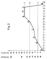
- FIG. 2 shows the gas pressure control possible in the course of a casting cycle with the device according to the invention in a pressure time diagram.
- the casting plant shown in FIG. 1 consists of a metal melting furnace 1, into which a riser pipe 2 projects obliquely up to its bottom, which at its outer end has a connecting flange 3 for coupling to a connecting flange 4 with a casting opening and a mold 5 with a mold cavity 6 Is provided.
- This contact probe consists of a contact plate 13 which is seated on a guide rod 14 actuated by the drive cylinder 12.
- the height of the probe 13 with the guide rod 14 can be adjusted and changed in the probe chamber 10 by the drive cylinder 12.
- the probe chamber 10 receiving the probe 13 is, with the exception of its lower inlet opening 8 for the casting material and the confluence with the furnace chamber 7 leading gas pressure compensation line 17 and a vent in the shuttle valve 18 hermetically sealed.
- a compressed gas supply line 19 opens into the furnace chamber.
- This compressed gas supply line is subdivided into six branch lines 20 to 25, which are brought together again before they open into the furnace chamber 7 and each have an open-close control valve 26.
- the branch lines 20 to 24 are also provided with fixed orifices 27 to 31 which determine the passage of the gas volume and which have different passage cross sections.
- the lines 20 to 25 provided with the fixed orifices can be opened individually or in any combination via their control valves 26, so that the volume of pressurized gas required for the required climbing speed in the riser pipe 2 can be introduced into the furnace chamber 7 via the pressurized gas supply line 19 .
- the control valve 26 in the branch line 25 also serves, together with the throttle valve 32 also arranged in this branch line, for regulating the leakage compensation.
- a vent line 33 with a vent valve 34 is connected to this line.
- a gas pressure measuring line 35 which leads to a measuring device 36 designed as a pressure-current converter, which transmits the gas pressure registered by him via line 35 in the furnace chamber 7 via electrical signals to an electrical control unit 37, which is used for the control the valves 11, 18, 26 and 34 is set up.
- the operation of the control device of this embodiment of the invention works as follows: First, the probe 13 is set at a height within the probe space 10, which corresponds approximately to the outlet opening of the riser pipe 2 in the area of its coupling flange 3.
- the shuttle valve 18 is switched so that the upper probe chamber is vented.
- corresponding adjustment of the control valves 26 in the branch lines 20 to 25 of the pressurized gas feed lines 19 introduces pressurized gas into the furnace chamber 7, until the metal melt in the probe chamber 10 builds up to the lower edge of the contact probe 13 due to the gas pressure thus built up in the furnace chamber has been pushed up.
- the contact between the pressed metal melt and the contact probe 13 is registered by the latter and reported to the electrical control unit 37, which then initiates further control of the compressed gas flow via the line 19 into the furnace chamber according to a predetermined program.
- the probe 13 is raised by the drive cylinder 12 within the probe space 10 to a height position in which it remains out of contact with the cast material pushed up in the probe space during the entire subsequent casting process and the shuttle valve 18 is switched over, so that the vent opening of the upper probe space is closed and the compressed gas compensation line 17 is opened, whereby the gas pressure in the furnace chamber 7 is transferred into the probe chamber 10 above the metal melt therein and the metal melt which has risen in this chamber is pressed back to the level of the melt in the furnace chamber 7.
- the gas pressure given at this point in time in the furnace space 7 is measured by the measuring device and its measurement result is passed on electrically to the electrical control device 37, which is the height given at that moment of the gas pressure in the furnace chamber 7 is used as a reference variable for the further control of the casting pressure in the furnace chamber.
- the numerals in the rectangles in FIG. 2 denote measuring points at which the pressure gas inflow and thus the further time course of the pressure rise in the furnace space undergoes a change in the course of a casting cycle.
- the first section of the curve located between the measuring points 1 and 2 shows the increase in the gas pressure up to the point in time at which the metal melt has reached the contact probe 13 in the probe chamber 10 set at the level of the coupling flange 3 of the riser pipe 2 (level line A).
- level line A level line A
- This pressure build-up phase is followed by the phase of the beginning of the filling of the mold cavity 6 in the mold 5, which is characterized by the curve section between the measuring points 2 and 3 of the pressure-time curve according to FIG. 2.
- the pressure increase per unit of time is somewhat less than in the previous pressure build-up phase.
- phase of the main mold filling which is characterized by the curve section between the measuring points 3 and 4 in FIG. 2, followed by the phase of the end of the mold filling with an increased pressure increase according to the curve section given between the measuring points 4 and 5, until the mold cavity 6 is completely filled (level line B).
- This phase is initially followed by a renewed increase in pressure, the holding pressure phase, which is characterized by the curve section between measuring points 5 and 6, and then the phase of the holding of this holding pressure, which is used for the make-up, which is characterized by the curve section between measuring points 6 and 7.
- the gas pressure in the furnace chamber 7 is reduced to zero by opening the vent valve 34, which is shown in FIG. 2 by the curve section between the measuring points 7 and 8.
- the still liquid metal from the sprue and riser pipe sinks back into the furnace.
- control valves 26 are opened or closed in different combinations, as can be seen from the following example:
- control valves remain in their set position in the individual phases of the casting cycle until the gas pressure in the furnace chamber 7, which is continuously measured by the measuring device 36, has reached the respective target pressure specified according to the control program.
- control and leakage loss valve 26 located in the branch line 25 is used, which according to the leaks determined by gas pressure measurement in the entire gas pressure system continuously allows a certain amount of compressed gas to flow into the furnace interior 7. Observing the constancy of the gas pressure during the holding pressure phase can serve to register changes in the total leakage losses and to compensate for them by adjusting the loss compensation accordingly.
Abstract
Description
Die Erfindung betrifft eine Vorrichtung und ein Verfahren zum Steuern und Regeln der Formfüllgeschwindigkeit und des Gießdruckes einer Niederdruckkokillengießmaschine, vorzugsweise für den Aluminiumguß, deren hermetisch abschließbarer, das flüssige Gießmaterial aufnehmender Ofenraum oder Behälter mit der Kokille über ein zu dieser führendes Steigrohr verbunden werden kann, über welches das Gießmaterial mittels in dem Ofenraum oder Behälter über eine Druckgaszuleitung aufgebauten Gasdruck in die Kokille gedrückt wird, wobei mindestens eine Kontaktsonde in einem in den Ofenraum oder Behälter von oben hineinragenden und an seinem unteren Ende für den Eintritt des Gießmaterials offenen Sondenraum in ihrer Höhenlage veränderbar angeordnet ist, die bei Kontakteintritt mit dem durch den Gasdruck im Sondendruck hochsteigenden Gießmaterial ein Signal an eine Einrichtung zur Steuerung des Druckgaszustromes zum Ofenraum gibt.The invention relates to a device and a method for controlling and regulating the mold filling speed and the casting pressure of a low-pressure die casting machine, preferably for aluminum casting, whose hermetically lockable furnace space or container which holds the liquid casting material can be connected to the mold via a riser pipe leading to it which the casting material is pressed into the mold by means of gas pressure built up in the furnace chamber or container via a compressed gas supply line, with at least one contact probe in a height that can be changed in a probe chamber which projects into the furnace chamber or container from above and is open at its lower end for the entry of the casting material is arranged which gives a signal to a device for controlling the pressure gas inflow to the furnace chamber when contact is made with the casting material rising due to the gas pressure in the probe pressure.
Eine derartige Steuervorrichtung unter Verwendung mindestens einer Kontaktsonde ist bereits bekannt (DE-AS 28 08 588). Bei dieser bekannten Vorrichtung wird eine ebenfalls in ihrer Höhenstellung verfahrbare Kontaktsonde dazu verwendet, den Gasdruck im Ofenraum über den gesamten Gießzyklus zu steuern und zu regeln. Die Kontaktsonde besitzt dort zwei Abtastnadeln mit in unterschiedlicher Höhe befindlichen Tastspitzen. Der Druckgaszustrom zum Ofenraum bzw. Behälter des Gießmaterials wird dabei so geregelt, daß der Niveauspiegel des Gießmaterials in dem im Steigrohr integrierten Sondenraum zwischen der unteren und der oberen Tastspitze der Kontaktsonde gehalten wird, wobei die Sonde in ihrer Höhenlage entsprechend dem gewünschten Gasdruck im Ofenraum bzw. Behälter eingestellt wird.Such a control device using at least one contact probe is already known (DE-AS 28 08 588). In this known device a contact probe, which can also be moved in its height position, is used to control and regulate the gas pressure in the furnace chamber over the entire casting cycle. The contact probe has two scanning needles with probe tips at different heights. The pressure gas flow to the furnace chamber or container of the casting material is regulated so that the level of the casting material is held in the probe chamber integrated in the riser pipe between the lower and the upper probe tip of the contact probe, the height of the probe corresponding to the desired gas pressure in the furnace chamber or Container is set.
Diese bekannte Vorrichtung hat den Nachteil, daß die Tastspitzen der Kontaktsonde während jeden Gießvorganges mehrfach oder sogar ständig mit dem flüssigen Gießmaterial in Kontakt stehen bzw. in dieses eintauchen, wodurch die Kontaktsonde wegen Anhaftung von Resten und Oxiden des Gießmaterials oder durch Anlösung durch das Gießmaterial rasch seine Funktionsgenauigkeit verliert. Außerdem besteht für den Sondenraum durch die zyklisch in ihm auf- und absteigende Schmelze die Gefahr des Zuwachsens durch auskristallisierende Schmelze des Gießmaterials, so daß dieser Raum ebenso wie das Steigrohr stark beheizt und durch regelmäßiges Ausputzen funktionsfähig gehalten werden muß.This known device has the disadvantage that the probe tips of the contact probe are in contact with or immersed in the liquid casting material several times or even continuously during each casting process, as a result of which the contact probe rapidly due to adhesion of residues and oxides of the casting material or through dissolution by the casting material loses its functional accuracy. In addition, there is the risk of growth due to the melt crystallizing out of the casting material for the probe space due to the cyclically rising and falling melt in it, so that this space, like the riser pipe, must be strongly heated and kept functional by regular cleaning.
Es sind auch Vorrichtungen zur Regelung des Gießdruckes bei Niederdruckkokillengießmaschinen bekannt (DE-AS 23 31 956), bei welchen der Gasdruck im Ofenraum bzw. im Behälter für das flüssige Gießmaterial rechnergesteuert entsprechend einer vorgegebenen Druck/Zeitkurve eingestellt und geregelt wird. Das Druckgas wird dort durch zwei Druckgaszuleitungen mit unterschiedlichem Strömungsquerschnitt zugeführt. Dabei sind mehrere Kontaktsonden vorgesehen, die unbeweglich über den Weg der Steighöhe des Gießmaterials angeordnet sind und über komplizierte pneumatische Regelorgane das teilweise oder gänzliche Öffnen und Schließen der beiden Druckgaszuleitungen bewirken und so einen in weiten Grenzen regelbaren Gasdruck entsprechend den Steuervorgaben gewährleisten. Diese Kontaktsonden tauchen bei jedem Gießzyklus erneut in das bis zu ihnen oder über sie hinaus hochgedrückte flüssige Gießmaterial ein, so daß sie mit dem gleichen Nachteil wie die Sonde bei der erstgenannten bekannten Vorrichtung behaftet sind.Devices for regulating the casting pressure in low-pressure die casting machines are also known (DE-AS 23 31 956), in which the gas pressure in the furnace space or in the container for the liquid casting material is set and controlled in a computer-controlled manner in accordance with a predetermined pressure / time curve. The pressurized gas is supplied through two pressurized gas feed lines with different flow cross sections. Here Several contact probes are provided, which are arranged immovably over the path of the rising height of the casting material and which partially or completely open and close the two compressed gas supply lines via complicated pneumatic control elements and thus ensure a gas pressure which can be regulated within wide limits in accordance with the control specifications. With each casting cycle, these contact probes are again immersed in the liquid casting material which is pushed up to or beyond them, so that they have the same disadvantage as the probe in the first known device.
Der Erfindung liegt daher die Aufgabe zugrunde, bei einer Vorrichtung und bei einem Verfahren der eingangs genannten Gattung die Funktionsfähigkeit der Kontaktsonde über eine große Anzahl von Gießzyklen unverändert aufrechtzuerhalten und damit Störungen bei der Regelung des Gießdruckes auszuschalten, sowie die Regelung der durch die Sonde eingeleiteten Druckgaszufuhr konstruktiv möglichst einfach und betriebssicher zu gestalten. Dies wird erfindungsgemäß dadurch erreicht, daß die Kontaktsonde bei Kontakteintritt mit dem durch den Gasdruck im Sondenraum hochsteigenden Gießmaterial, bei welchem sie ein Signal an eine Einrichtung zur Regelung des Druckgaszustromes zum Ofenraum oder Behälter gibt, in dem sie aufnehmenden Sondenraum in eine solch höhere Lage bewegbar ist, die während des Gießvorganges von dem Niveau des Gießmaterials nicht erreicht wird, und daß eine Meßeinrichtung für die Messung des im oberen Bereich des Ofenraumes oder Behälters für das Gießmaterial gegebenen Gasdruckes vorgesehen ist, die den gemessenen Gasdruck in Form eines Signals an die Einrichtung zur Steuerung des Druckgasstromes weitergibt. Die Kontaktsonde tritt also während eines Gießzyklusses nur einmal in Funktion, wobei sie der Einrichtung zur Steuerung des Druckgaszustromes den Kontakteintritt anzeigt, wodurch der Ablauf der weiteren Steuerung und Regelung des Gasdruckes im Ofenraum oder Behälter im Zeitablauf nach einem vorgegebenen Programm eingeleitet werden kann. Dabei kann der in diesem Augenblick von der Meßeinrichtung im Ofenraum oder Behälter gemessene Gasdruck als Referenzdruck für den weiteren Steuerungsablauf verwendet werden. Für die weitere Regelung des Gasdruckes im Ofenraum kann mit der vorgesehenen Druckmeßeinrichtung der im Ofenraum oder Behälter gegebene Gasdruck laufend erneut gemessen und nach Maßgabe der jeweils gemessenen Istdrücke sowie der von der Steuerung vorgegebenen Solldrücke der Druckgaszustrom zum Ofenraum oder Behälter geregelt werden.The invention is therefore based on the object, in a device and in a method of the type mentioned, to maintain the functionality of the contact probe unchanged over a large number of casting cycles and thus to eliminate disturbances in the regulation of the casting pressure, and to regulate the compressed gas supply introduced by the probe structurally as simple and reliable as possible. This is achieved according to the invention in that the contact probe upon contact with the casting material rising due to the gas pressure in the probe chamber, in which it gives a signal to a device for regulating the pressure gas flow to the furnace chamber or container, in which it receives the probe chamber in such a higher position which is not reached during the casting process by the level of the casting material, and that a measuring device is provided for measuring the gas pressure given in the upper region of the furnace space or container for the casting material, which measures the measured gas pressure in the form of a signal to the device Control of the compressed gas flow passes. The contact probe therefore only operates once during a casting cycle, and it indicates the contact entry to the device for controlling the pressure gas inflow, as a result of which the further control and regulation of the gas pressure in the furnace chamber or container over time after a predetermined time Program can be initiated. The gas pressure measured at that moment by the measuring device in the furnace chamber or container can be used as a reference pressure for the further control process. For the further regulation of the gas pressure in the furnace chamber, the gas pressure given in the furnace chamber or container can be continuously measured again with the provided pressure measuring device and the pressure gas inflow to the furnace chamber or container can be regulated in accordance with the respectively measured actual pressures and the target pressures specified by the control.
Der bei der erfindungsgemäßen Vorrichtung und diesem Verfahren nur einmal während eines ganzen Gießzyklusses gegebene kurze Kontakt zwischen der Kontaktsonde und dem im Sondenraum hochgedrückten Gießmaterial gewährleistet, daß die Kontaktsonde weitgehend geschont und von einer Verkrustung durch Gießmaterial freigehalten wird.The short contact between the contact probe and the casting material pushed up in the probe space in the device and this method according to the invention and only once during an entire casting cycle ensures that the contact probe is largely spared and kept free from incrustation by casting material.
Die Kontaktsonde kann in eine solche Höhenlage im Sondenraum einstellbar sein, daß ihre Abtastspitze etwa in Höhe der mit der Kokille verbindbaren Austrittsöffnung des Steigrohres liegt. Diese Höhenlage entspricht etwa dem Gießmaterialspiegel kurz vor Beginn der Formfüllung, also einem Niveau, das sich geringfügig unterhalb des Formhohlraumes befindet.The contact probe can be set in such a high position in the probe space that its scanning tip lies approximately at the height of the outlet opening of the riser tube which can be connected to the mold. This height corresponds approximately to the level of the casting material shortly before the mold is filled, i.e. a level that is slightly below the mold cavity.
Zweckmäßig ist der Sondenraum mit Ausnahme seiner unteren Öffnung für den Eintritt des Gießmaterials hermetisch abschließbar, so daß oberhalb des in diesem Raum hochsteigenden Gießmaterials ein Gasdruck aufgebaut werden kann, der ein Hochsteigen des Gießmaterials bis zur Kontaktsonde in ihrer hochgezogenen Stellung mit Sicherheit verhindert. Zu diesem Zweck kann der Sondenraum in seinem oberen Bereich über eine mit einem Absperrventil versehene Druckgasausgleichsleitung mit dem Ofenraum oder Behälter für das flüssige Gießmaterial in Verbindung stehen. Dieses Absperrorgan kann ein Wechselventil sein, welches so steuerbar ist, daß es bei Beginn eines Gießzyklusses zunächst den oberen Sondenraum zur Außenluft hin öffnet (Entlüftungsstellung) bei Kontakteintritt der Kontaktsonde mit dem im Sondenraum hochgedrücktem Gießmaterial die Entlüftungsöffnung schließt und die Druckausgleichsleitung zum Ofenraum öffnet und damit den Gasdruckausgleich zwischen Sondenraum und Ofenraum herstellt.The probe chamber is expediently hermetically sealed, with the exception of its lower opening, for the entry of the casting material, so that a gas pressure can be built up above the casting material rising in this chamber, which prevents the casting material from rising up to the contact probe in its raised position with certainty. For this purpose, the upper part of the probe chamber can be connected to the furnace chamber or to the compressed gas compensation line with a shut-off valve Connect the container for the liquid casting material. This shut-off device can be a shuttle valve which can be controlled so that at the start of a casting cycle it first opens the upper probe chamber to the outside air (vent position) when the contact probe comes into contact with the casting material that is pushed up in the probe chamber, closes the vent opening and opens the pressure compensation line to the furnace chamber and thus establishes the gas pressure balance between the probe chamber and the furnace chamber.
Zur Regelung des Gasdruckes im Ofenraum ist der Durchtrittsquerschnitt der Druckgaszuleitung zweckmäßig in Abhängigkeit von dem im Ofenraum bzw. Behälter vom Steuerungsprogramm vorgegebenen Gasdruck veränderbar. Um die Einstellung des Durchtrittsquerschnittes und damit der Menge des dem Ofenraum zuzuleitenden Druckgases mit möglichst einfachen Regelorganen zu gewährleisten, ist bei einer bevorzugten Ausführungsform die Druckgaszuleitung in mehrere Zweigleitungen unterteilt, die vor Einmündung in den Ofenraum oder Behälter wieder zusammengeführt sind und jeweils einen unveränderlichen Durchtrittsquerschnitt, vorzugsweise in Form einer Festblende, für das Druckgas sowie ein Absperrventil haben. Die Festenblenden können unterschiedliche Durchtrittsöffnungen haben und einzeln oder in beliebiger Kombination von der Einrichtung zur Regelung des Druckgaszustromes geöffnet oder geschlossen werden, wodurch der jeweils benötigte Druckgaszustrom zum Ofen oder Behälter, der für die Steiggeschwindigkeit des Gießmaterials im Steigrohr verantwortlich ist, genau geregelt werden kann. Diese einfache Zu- und Aufregelung ist billig, technisch unproblematisch und von geringster Störanfälligkeit.To regulate the gas pressure in the furnace chamber, the passage cross section of the compressed gas supply line can expediently be changed as a function of the gas pressure specified in the furnace chamber or container by the control program. In order to ensure the setting of the passage cross-section and thus the amount of the compressed gas to be fed to the furnace chamber with the simplest possible control elements, in a preferred embodiment the compressed gas feed line is divided into a plurality of branch lines which are brought together again before they enter the furnace chamber or container and each have an unchangeable passage cross-section, preferably in the form of a fixed orifice, for the compressed gas and a shut-off valve. The fixed orifices can have different through-openings and can be opened or closed individually or in any combination by the device for regulating the pressure gas inflow, as a result of which the pressure gas inflow required to the furnace or container, which is responsible for the rate of rise of the casting material in the riser pipe, can be precisely regulated. This simple control and regulation is cheap, technically unproblematic and least susceptible to malfunction.
In Fig. 1 der Zeichnung ist ein besonders vorteilhaftes Ausführungsbeispiel der erfindungsgemäßen Steuervorrichtung bei einer Niederdruck-Gießanlage für Aluminiumguß dargestellt, das im folgenden näher beschrieben wird.1 of the drawing shows a particularly advantageous exemplary embodiment of the control device according to the invention in a low-pressure casting system for aluminum casting, which is described in more detail below.
Fig. 2 zeigt die im Laufe eines Gießzyklusses mit der erfindungsgemäßen Vorrichtung mögliche Gasdrucksteuerung in einem Druckzeitdiagramm.2 shows the gas pressure control possible in the course of a casting cycle with the device according to the invention in a pressure time diagram.
Die in Fig. 1 dargestellte Gießanlage besteht aus einem Metallschmelzofen 1, in welchen bis nahe zu seinem Boden ein Steigrohr 2 schräg hineinragt, das an seinem äußeren Ende mit einem Verbindungsflansch 3 zur Ankoppelung an einen eine Eingußöffnung aufweisenden Verbindungsflansch 4 einer Kokille 5 mit Formhohlraum 6 ausgestattet ist. In den Ofenraum 7 ragt ebenfalls von oben bis nahe an dessen Boden heran ein an seinem unteren Ende 8 offener Rohrkörper 9 hinein, der einen Sondenraum 10 begrenzt, in welchem eine elektrische Kontaktsonde mittels eines pneumatisch oder hydraulisch über ein Ventil 11 gesteuerten Antriebszylinders 12 höhenverstellbar angeordnet ist. Diese Kontaktsonde besteht aus einer Kontaktplatte 13, die an einer von dem Antriebszylinder 12 betätigten Führungsstange 14 sitzt. Mit 15 ist das Niveau des im Metallschmelzofen 1 befindlichen Gießmaterials, der Metallschmelze, angegeben, welches durch einen verschließbaren Einlaß 16 in den Ofenraum 7 eingefüllt werden kann. Durch den Antriebszylinder 12 kann die Sonde 13 mit Führungsstange 14 in ihrer Höhenlage im Sondenraum 10 eingestellt und verändert werden.The casting plant shown in FIG. 1 consists of a
Der die Sonde 13 aufnehmende Sondenraum 10 ist mit Ausnahme seiner unteren Eintrittsöffnung 8 für das Gießmaterial sowie der Einmündung einer zum Ofenraum 7 führenden Gasdruckausgleichsleitung 17 und einer Entlüftungsöffnung im Wechselventil 18 hermetisch abgeschlossen. Neben der Druckgasausgleichsleitung 17 mündet in den Ofenraum eine Druckgaszuleitung 19 ein. Diese Druckgaszuleitung ist in sechs Zweigleitungen 20 bis 25 unterteilt, die vor Einmündung in den Ofenraum 7 wieder zusammengeführt sind und jeweils ein Auf-Zu-Steuerventil 26 aufweisen. Die Zweigleitungen 20 bis 24 sind ferner mit den Durchtritt des Gasvolumens bestimmenden Festblenden 27 bis 31 versehen, die unterschiedlichen Durchtrittsquerschnitt haben. Die mit den Festblenden versehenen Leitungen 20 bis 25 können über ihre Steuerventile 26 einzeln oder in beliebiger Kombination geöffnet werden, so daß über sie das jeweils für die erforderliche Steiggeschwindigkeit im Steigrohr 2 erforderliche Volumen an Druckgas über die Druckgaszuleitung 19 in den Ofenraum 7 eingeleitet werden kann. Das Steuerventil 26 in der Zweigleitung 25 dient zusammen mit dem ebenfalls in dieser Zweigleitung angeordneten Drosselventil 32 außerdem zur Einregulierung des Leckageausgleichs.The
Damit die Druckgaszuleitung 19 auch zur Entlüftung des Ofenraumes 7 verwendet werden kann, ist an diese Leitung eine Entlüftungsleitung 33 mit einem Entlüftungsventil 34 angeschlossen. In den Ofenraum 7 mündet ferner eine Gasdruckmeßleitung 35 ein, die zu einem als Druck-Stromwandler ausgebildeten Meßgerät 36 führt, das den von ihm über die Leitung 35 registrierten Gasdruck im Ofenraum 7 über elektrische Signale an ein elektrisches Steuergerät 37 weitergibt, das für die Steuerung der Ventile 11, 18, 26 und 34 eingerichtet ist.So that the compressed
Die Arbeitsweise der Steuervorrichtung dieses Ausführungsbeispiels der Erfindung arbeitet wie folgt: Zunächst wird die Sonde 13 in einer Höhenlage innerhalb des Sondenraumes 10 eingestellt, die etwa der Austrittsöffnung des Steigrohres 2 im Bereich dessen Ankoppelungsflansches 3 entspricht. Das Wechselventil 18 ist so geschaltet, daß der obere Sondenraum entlüftet ist. Sodann wird bei geschlossenem Entlüftungsventil 34 über entsprechende Einstellung der Steuerventile 26 in den Zweigleitungen 20 bis 25 der Druckgaszuleitungen 19 Druckgas in den Ofenraum 7 eingebracht, bis durch den dadurch über der Metallschmelze im Ofenraum aufgebauten Gasdruck die Metallschmelze im Sondenraum 10 bis zur Unterkante der Kontaktsonde 13 hochgedrückt worden ist. Der Kontakteintritt zwischen der hochgedrückten Metallschmelze und der Kontaktsonde 13 wird von dieser registriert und an das elektrische Steuergerät 37 gemeldet, das dann nach einem vorgegebenen Programm die weitere Steuerung des Druckgasstromes über die Leitung 19 in den Ofenraum veranlaßt. Gleichzeitig wird die Sonde 13 durch den Antriebszylinder 12 innerhalb des Sondenraumes 10 in eine Höhenlage hochgezogen, in der sie während des gesamten folgenden Gießvorganges außerhalb eines Kontaktes mit dem im Sondenraum hochgedrückten Gießmaterial bleibt und das Wechselventil 18 wird umgeschaltet, so daß die Entlüftungsöffnung des oberen Sondenraumes geschlossen und die Druckgasausgleichsleitung 17 geöffnet wird, wodurch der im Ofenraum 7 befindliche Gasdruck in den Sondenraum 10 oberhalb der darin befindlichen Metallschmelze übergeleitet und die in diesem Raum hochgestiegene Metallschmelze auf das Niveau der im Ofenraum 7 befindlichen Schmelze zurückgedrückt wird.The operation of the control device of this embodiment of the invention works as follows: First, the
Außerdem wird der zu diesem Zeitpunkt im Ofenraum 7 gegebene Gasdruck durch das Meßgerät gemessen und dessen Meßergebnis elektrisch an das elektrische Steuergerät 37 weitergegeben, das die in diesem Augenblick gegebene Höhe des Gasdrucks im Ofenraum 7 als Referenzgröße für die weitere Steuerung des Gießdruckes im Ofenraum verwendet.In addition, the gas pressure given at this point in time in the
Ab diesem Zeitpunkt wird die weitere zeitliche Steuerung und Regelung des Gießdruckes und damit die Steiggeschwindigkeit und Steighöhe der durch das Steigrohr 2 in den Formhohlraum 6 der Kokille 5 einzubringenden Metallschmelze durch Steuerung des Volumenstromes des in den Ofenraum 7 über die Druckgasleitung 19 einzuleitenden Druckgases über der Zeit entsprechend einer vorprogrammierten Druck-Zeit-Kurve 38 durchgeführt, wie sie aus Fig. 2 ersichtlich ist.From this point in time, the further time control and regulation of the casting pressure and thus the rate of rise and height of the molten metal to be introduced through the
Die in den Rechtecken befindlichen Ziffern in Fig. 2 bezeichnen Meßpunkte, an denen im Verlauf eines Gießzyklusses der Druckgaszustrom und damit der weitere zeitliche Verlauf des Druckanstieges im Ofenraum eine Änderung erfährt. Der erste zwischen den Meßpunkten 1 und 2 befindliche Kurvenabschnitt zeigt den Anstieg des Gasdruckes bis zu dem Zeitpunkt, zu dem die Metallschmelze die auf Höhe des Ankopplungsflansches 3 des Steigrohres 2 eingestellte Kontaktsonde 13 im Sondenraum 10 erreicht hat (Niveaulinie A). Während dieser Phase des Druckanstieges im Ofen sind sämtliche Steuerventile 20 bis 25 in der Gasdruckzuleitung 19 geöffnet. An diese Druckaufbauphase schließt sich die Phase des Beginns der Füllung des Formhohlraumes 6 in der Kokille 5 an, die durch den Kurvenabschnitt zwischen den Meßpunkten 2 und 3 der Druck-Zeit-Kurve gemäß Fig. 2 gekennzeichnet ist. Der Druckanstieg pro Zeiteinheit ist, wie aus Fig. 2 hervorgeht, etwas geringer als in der vorangehenden Druckaufbauphase.The numerals in the rectangles in FIG. 2 denote measuring points at which the pressure gas inflow and thus the further time course of the pressure rise in the furnace space undergoes a change in the course of a casting cycle. The first section of the curve located between the
Darauf folgt die Phase der hauptsächlichen Formfüllung, die durch den Kurvenabschnitt zwischen den Meßpunkten 3 und 4 in Fig. 2 gekennzeichnet ist, worauf sich die Phase des Endes der Formfüllung mit einem verstärkten Druckanstieg gemäß dem zwischen den Meßpunkten 4 und 5 gegebenen Kurvenabschnitt anschließt, bis der Formhohlraum 6 vollständig gefüllt ist (Niveaulinie B). Auf diese Phase folgt zunächst mit erneut verstärktem Druckanstieg die Nachdruckphase, die durch den Kurvenabschnitt zwischen den Meßpunkten 5 und 6 gekennzeichnet ist, und dann die Phase der zur Formnachspeisung dienenden Aufrechterhaltung dieses Nachdruckes, die durch den Kurvenabschnitt zwischen den Meßpunkten 6 und 7 gekennzeichnet ist. Am Ende dieser Nachdruckphase wird durch Öffnen des Entlüftungsventils 34 der Gasdruck im Ofenraum 7 auf Null abgebaut, was in Fig. 2 durch den Kurvenabschnitt zwischen den Meßpunkten 7 und 8 dargestellt ist. Dabei sinkt das noch flüssige Metall aus Angußlauf und Steigrohr in den Ofen zurück.This is followed by the phase of the main mold filling, which is characterized by the curve section between the
Je nach Stärke des gewünschten Druckaufbaus in den Kurvenabschnitten zwischen den Meßpunkten 1 bis 6 werden die Steuerventile 26 in unterschiedlicher Kombination geöffnet oder geschlossen, wie es sich aus folgendem Beispiel ergibt:

Die Steuerventile bleiben in den einzelnen Phasen des Gießzyklusses so lange in ihrer eingestellten Stellung, bis der von dem Meßgerät 36 laufend gemessene Gasdruck im Ofenraum 7 den jeweiligen nach dem Steuerprogramm vorgegebenen Solldruck erreicht hat.The control valves remain in their set position in the individual phases of the casting cycle until the gas pressure in the
Zur Aufrechterhaltung des Nachdruckes für die Dauer der vorgenannten Nachspeisungsphase dient das in der Zweigleitung 25 befindliche Regel- und Leckageverlustventil 26, welches entsprechend den durch Gasdruckmessung ermittelten Undichtigkeiten im gesamten Gasdrucksystem ständig eine bestimmte Menge Druckgas in den Ofeninnenraum 7 einströmen läßt. Die Beobachtung der Konstanz des Gasdruckes während der Nachdruckphase kann dazu dienen, Veränderungen in den Gesamtleckverlusten zu registrieren und durch entsprechende Nachregulierung des Verlustausgleiches zu kompensieren.To maintain the holding pressure for the duration of the aforementioned make-up phase, the control and
Claims (13)
- Device for controlling and regulating the mold filling speed and casting pressure of a low pressure chill casting machine, whose hermetically closable furnace chamber (7) receiving the casting material is connected to the chill mold (5) via a riser tube (2) leading to this, via which the casting material is pressed into the chill mold (5) by means of gas pressure established in the furnace chamber (7) via a pressure gas feed line (19), at least one contact probe (13) being arranged at an adjustable height in a probe chamber (10) extending into the furnace chamber (7) from above and being open at its lower end for the entry of the casting material, which probe provides a signal to an arrangement (37) for controlling the pressure gas inflow to the furnace chamber on the onset of contact with the casting material rising in the probe chamber (10) as a result of the gas pressure,
characterized in that on onset of contact the contact probe (13) is adjustable in the probe chamber (10), which receives the contact probe, to a height position which is not reached during the casting process by the level of liquid casting material, and in that a measuring arrangement (36) is provided for measuring the gas pressure in the furnace chamber (7) which arrangement provides the measured pressure in the form of a signal to the arrangement (37) for controlling the pressure gas inflow. - Device according to claim 1
charcterized in that the contact probe (13) is movable up and down by a pneumatically or hydraulically controlled drive cylinder (12). - Device according to claim 1
characterized in that the contact probe (13) is adjustable in the probe chamber (10) to a height position such that its sensing points lie approximately at the height of the outlet opening of the riser tube (2) connectable to the chill mold (5). - Device according to claim 1
characterized in that the probe chamber has a closable ventilation opening in its upper region. - Device according to claim 1 or 4
characterized in that the probe chamber (10) can be hermetically sealed with the exception of its lower opening end (8) for the entry of the casting material. - Device according to claim 4
characterized in that the probe chamber (10) is connected at its upper region to the furnace chamber (7) via a pressure gas equalization line (17) closable by a changeover valve (18). - Device according to claim 4 and 6
characterized in that the changeover valve (18) is controllable in such a manner that upon onset of contact of the contact probe (13) with the casting material pressed up in the probe chamber (10) it switches such that the ventilation opening of the probe chamber is closed and the pressure equalization line (17) is open. - Device according to claim 1
characterized in that the aperture cross-section of the pressure gas feed line (19) can be changed in dependence upon the desired gas pressure in the furnace chamber. - Device according to claim 8
characterized in that for setting the desired gas pressure in the furnace chamber (7) the pressure gas feed line (19) is sub-divided into a plurality of branch lines (20 to 25) which are brought together again before discharge into the furnace chamber and which have respective fixed aperture cross-section (calibrated apertures 27 to 31) for the pressure gas and a control valve (26) constructed as an open-shut valve. - Device according to claim 9
characterized in that the control valves are controllable by an arrangement (37) for controlling the pressure gas feed flow. - Device according to claim 1
characterized in that the pressure gas feed line (19) discharging into the furnace chamber (7) a leak valve (26, 32) is arranged which is controllable in dependence upon the gas pressure losses caused by leakage as measured in the furnace chamber. - Method for controlling the casting pressure of a low pressure chill casting apparatus (metal casting apparatus by means of a contact probe (13) according to one or more of claims 1 to 11, the contact probe being adjustable in height in a probe chamber (10), which extends into the furnace chamber (7), and providing a signal to an arrangement (37) for controlling the pressure gas inflow to the furnace chamber (7) upon onset of contact with the casting material rising in the probe chamber (10) as a result of the gas pressure characterized in that on the onset of contact of the contact probe (13) with the casting material pressed up in the probe chamber (10) the gas pressure in the furnace chamber (7) is measured and via an electrical signal is used as reference pressure for further control of the pressure gas feed flow to the furnace chamber.
- Method according to claim 12
characterized in that after onset of contact of the contact probe (13) with the casting material pressed up in the probe chamber (10) the gas pressure in the furnace chamber (7) is continually measured and the gas pressure feed flow to the furnace chamber is controlled according to the respective desired pressure in the furnace chamber pre-set by the control programme.
Applications Claiming Priority (2)
| Application Number | Priority Date | Filing Date | Title |
|---|---|---|---|
| DE3924775 | 1989-07-26 | ||
| DE3924775A DE3924775C1 (en) | 1989-07-26 | 1989-07-26 |
Publications (2)
| Publication Number | Publication Date |
|---|---|
| EP0483191A1 EP0483191A1 (en) | 1992-05-06 |
| EP0483191B1 true EP0483191B1 (en) | 1993-05-26 |
Family
ID=6385907
Family Applications (1)
| Application Number | Title | Priority Date | Filing Date |
|---|---|---|---|
| EP90910641A Expired - Lifetime EP0483191B1 (en) | 1989-07-26 | 1990-07-25 | Process and device for controlling and regulating the mould filling rate and casting pressure of a low-pressure chill casting machine |
Country Status (14)
| Country | Link |
|---|---|
| EP (1) | EP0483191B1 (en) |
| JP (1) | JPH04506934A (en) |
| KR (1) | KR920700811A (en) |
| AT (1) | ATE89773T1 (en) |
| AU (1) | AU6043590A (en) |
| BR (1) | BR9007556A (en) |
| CA (1) | CA2053922A1 (en) |
| DD (1) | DD295571A5 (en) |
| DE (2) | DE3924775C1 (en) |
| DK (1) | DK0483191T3 (en) |
| ES (1) | ES2040600T3 (en) |
| MY (1) | MY106433A (en) |
| PT (1) | PT94821A (en) |
| WO (1) | WO1991001833A1 (en) |
Families Citing this family (11)
| Publication number | Priority date | Publication date | Assignee | Title |
|---|---|---|---|---|
| AT396439B (en) * | 1991-05-13 | 1993-09-27 | Sommerhuber Franz | Apparatus for permanent-mould casting of sections of large dimensions, in particular hollow sections, from light alloy |
| FR2705044B1 (en) * | 1993-05-10 | 1995-08-04 | Merrien Pierre | LOW PRESSURE PILOT CASTING PROCESS OF A VACUUM MOLD FOR ALUMINUM OR MAGNESIUM ALLOYS AND DEVICE FOR ITS IMPLEMENTATION. |
| DE19821419A1 (en) * | 1998-05-13 | 1999-11-18 | Georg Fischer Disa Ag | Process for increasing low pressure casting of metal, especially light metal |
| DE19834553A1 (en) * | 1998-07-31 | 2000-02-03 | Georg Fischer Disa Ag | Method and device for increasing the casting of light metal |
| DE19905874C2 (en) * | 1999-02-12 | 2003-07-24 | Vaw Alucast Gmbh | Device for filling molds |
| DE10061026A1 (en) * | 2000-12-08 | 2002-06-13 | Bayerische Motoren Werke Ag | Metal casting process and device |
| DE10352179B4 (en) * | 2003-11-05 | 2007-09-06 | Dihag Deutsche Giesserei- Und Industrie-Holding Ag | Low pressure casting process for the production of a casting |
| JP5073392B2 (en) * | 2007-07-11 | 2012-11-14 | 東京窯業株式会社 | Ladle |
| CN102211170A (en) * | 2011-05-20 | 2011-10-12 | 江苏天宏机械工业有限公司 | Highly turbocharged low pressure die casting machine |
| US8327915B1 (en) * | 2011-05-25 | 2012-12-11 | GM Global Technology Operations LLC | Pour ladle for molten metal |
| CN108620557A (en) * | 2018-05-25 | 2018-10-09 | 东莞市镁正隆工业熔炉设备有限公司 | A kind of alloy die cast feed delicate metering equipment and its working method |
Family Cites Families (3)
| Publication number | Priority date | Publication date | Assignee | Title |
|---|---|---|---|---|
| US4153100A (en) * | 1975-10-27 | 1979-05-08 | Institut Po Metaloznanie I Technologia Na Metalite | Low-pressure or counterpressure casting apparatus |
| FR2382298A1 (en) * | 1977-03-01 | 1978-09-29 | Renault | LOW PRESSURE LIQUID METAL CASTING DEVICE |
| US4585050A (en) * | 1981-01-05 | 1986-04-29 | Etude Et Developpement En Metallurgie, E.D.E.M., S.A.R.L. | Process for automatic regulation of a casting cycle |
-
1989
- 1989-07-26 DE DE3924775A patent/DE3924775C1/de not_active Expired - Fee Related
-
1990
- 1990-07-25 DE DE9090910641T patent/DE59001574D1/en not_active Expired - Fee Related
- 1990-07-25 EP EP90910641A patent/EP0483191B1/en not_active Expired - Lifetime
- 1990-07-25 WO PCT/EP1990/001223 patent/WO1991001833A1/en active IP Right Grant
- 1990-07-25 AU AU60435/90A patent/AU6043590A/en not_active Abandoned
- 1990-07-25 DK DK90910641.1T patent/DK0483191T3/en active
- 1990-07-25 ES ES199090910641T patent/ES2040600T3/en not_active Expired - Lifetime
- 1990-07-25 KR KR1019910701516A patent/KR920700811A/en not_active Application Discontinuation
- 1990-07-25 JP JP2510299A patent/JPH04506934A/en active Pending
- 1990-07-25 CA CA002053922A patent/CA2053922A1/en not_active Abandoned
- 1990-07-25 MY MYPI90001247A patent/MY106433A/en unknown
- 1990-07-25 DD DD90343060A patent/DD295571A5/en not_active IP Right Cessation
- 1990-07-25 AT AT90910641T patent/ATE89773T1/en active
- 1990-07-25 BR BR909007556A patent/BR9007556A/en unknown
- 1990-07-26 PT PT94821A patent/PT94821A/en not_active Application Discontinuation
Also Published As
| Publication number | Publication date |
|---|---|
| KR920700811A (en) | 1992-08-10 |
| PT94821A (en) | 1991-03-20 |
| DE3924775C1 (en) | 1990-03-29 |
| DK0483191T3 (en) | 1993-06-21 |
| AU6043590A (en) | 1991-03-11 |
| CA2053922A1 (en) | 1991-01-27 |
| DE59001574D1 (en) | 1993-07-01 |
| BR9007556A (en) | 1992-06-23 |
| DD295571A5 (en) | 1991-11-07 |
| WO1991001833A1 (en) | 1991-02-21 |
| ATE89773T1 (en) | 1993-06-15 |
| MY106433A (en) | 1995-05-30 |
| ES2040600T3 (en) | 1993-10-16 |
| JPH04506934A (en) | 1992-12-03 |
| EP0483191A1 (en) | 1992-05-06 |
Similar Documents
| Publication | Publication Date | Title |
|---|---|---|
| EP0483191B1 (en) | Process and device for controlling and regulating the mould filling rate and casting pressure of a low-pressure chill casting machine | |
| DE2433060C2 (en) | A method of pouring predetermined quantities of molten metal and apparatus for carrying out this method | |
| DE4239558A1 (en) | Process for producing negative pressure in a die casting machine | |
| EP0324937A1 (en) | Apparatus for introducing a fluid substance into a carrier gas, and method for operating the apparatus | |
| EP2572588B1 (en) | Device and a method for distributing flowing or self-levelling masses, in particular aerated chocolate | |
| EP0221196B1 (en) | Method of and installation for casting under pressure | |
| EP0594679B1 (en) | Process for producing castings using a die-casting machine | |
| DE3020076C2 (en) | Control device for an automatic casting plant | |
| DE2851256C2 (en) | ||
| DE3233817A1 (en) | DEVICE FOR FEEDING LIQUID METAL TO A CASTING MACHINE | |
| EP1080809B1 (en) | Method for controlling the distribution of quantity of liquid metal | |
| DE10151423A1 (en) | Airflow adjusting apparatus for printing machine has airflow adjusting device that adjusts airflow used in sheet conveyance based on driving parameters of air | |
| DE4419848C1 (en) | Hot chamber die casting machine | |
| DE2616430A1 (en) | METHOD AND DEVICE FOR EJECTING BULK MATERIALS FROM A PRESSURE-RESISTANT SILO CONTAINER | |
| DE2808588A1 (en) | DEVICE FOR POURING LIQUID METAL UNDER LOW PRESSURE | |
| DE2431892A1 (en) | DEVICE FOR DOSED DISPENSING OF LIQUID METAL | |
| DE2533070C3 (en) | Process for the metered delivery of bulk goods | |
| DE2454238C2 (en) | Method and device for settling or compacting quark | |
| CH646624A5 (en) | Process for casting molten metal under the pressure of a protective gas and apparatus for carrying out the process | |
| DE19855377A1 (en) | Method and device for filling containers | |
| DE2830840B2 (en) | Method and device for regulating the bath level during continuous casting | |
| DE3624392C2 (en) | ||
| DE1508955C2 (en) | Method and device for automatic electrical and continuous control of the fill level in continuous casting molds with the aid of the stopper position in an upstream intermediate container | |
| DE865792C (en) | Press furnace for dental purposes | |
| DE19823134C1 (en) | Method and device for the production of moldings for foundry purposes from sand |
Legal Events
| Date | Code | Title | Description |
|---|---|---|---|
| PUAI | Public reference made under article 153(3) epc to a published international application that has entered the european phase |
Free format text: ORIGINAL CODE: 0009012 |
|
| 17P | Request for examination filed |
Effective date: 19910821 |
|
| AK | Designated contracting states |
Kind code of ref document: A1 Designated state(s): AT BE CH DE DK ES FR GB IT LI NL SE |
|
| 17Q | First examination report despatched |
Effective date: 19920924 |
|
| GRAA | (expected) grant |
Free format text: ORIGINAL CODE: 0009210 |
|
| AK | Designated contracting states |
Kind code of ref document: B1 Designated state(s): AT BE CH DE DK ES FR GB IT LI NL SE |
|
| REF | Corresponds to: |
Ref document number: 89773 Country of ref document: AT Date of ref document: 19930615 Kind code of ref document: T |
|
| ITF | It: translation for a ep patent filed |
Owner name: BARZANO' E ZANARDO MILANO S.P.A. |
|
| REG | Reference to a national code |
Ref country code: DK Ref legal event code: T3 |
|
| GBT | Gb: translation of ep patent filed (gb section 77(6)(a)/1977) |
Effective date: 19930601 |
|
| REF | Corresponds to: |
Ref document number: 59001574 Country of ref document: DE Date of ref document: 19930701 |
|
| PGFP | Annual fee paid to national office [announced via postgrant information from national office to epo] |
Ref country code: SE Payment date: 19930719 Year of fee payment: 4 |
|
| PG25 | Lapsed in a contracting state [announced via postgrant information from national office to epo] |
Ref country code: LI Effective date: 19930731 Ref country code: CH Effective date: 19930731 |
|
| PGFP | Annual fee paid to national office [announced via postgrant information from national office to epo] |
Ref country code: NL Payment date: 19930731 Year of fee payment: 4 |
|
| ET | Fr: translation filed | ||
| PGFP | Annual fee paid to national office [announced via postgrant information from national office to epo] |
Ref country code: BE Payment date: 19930812 Year of fee payment: 4 |
|
| PGFP | Annual fee paid to national office [announced via postgrant information from national office to epo] |
Ref country code: AT Payment date: 19930817 Year of fee payment: 4 |
|
| PGFP | Annual fee paid to national office [announced via postgrant information from national office to epo] |
Ref country code: DK Payment date: 19930930 Year of fee payment: 4 |
|
| REG | Reference to a national code |
Ref country code: ES Ref legal event code: FG2A Ref document number: 2040600 Country of ref document: ES Kind code of ref document: T3 |
|
| PLBE | No opposition filed within time limit |
Free format text: ORIGINAL CODE: 0009261 |
|
| REG | Reference to a national code |
Ref country code: CH Ref legal event code: PL |
|
| STAA | Information on the status of an ep patent application or granted ep patent |
Free format text: STATUS: NO OPPOSITION FILED WITHIN TIME LIMIT |
|
| 26N | No opposition filed | ||
| PGFP | Annual fee paid to national office [announced via postgrant information from national office to epo] |
Ref country code: GB Payment date: 19940719 Year of fee payment: 5 |
|
| PGFP | Annual fee paid to national office [announced via postgrant information from national office to epo] |
Ref country code: ES Payment date: 19940721 Year of fee payment: 5 |
|
| PG25 | Lapsed in a contracting state [announced via postgrant information from national office to epo] |
Ref country code: DK Effective date: 19940725 Ref country code: AT Effective date: 19940725 |
|
| REG | Reference to a national code |
Ref country code: DK Ref legal event code: EBP |
|
| PG25 | Lapsed in a contracting state [announced via postgrant information from national office to epo] |
Ref country code: SE Effective date: 19940726 |
|
| PGFP | Annual fee paid to national office [announced via postgrant information from national office to epo] |
Ref country code: FR Payment date: 19940728 Year of fee payment: 5 Ref country code: DE Payment date: 19940728 Year of fee payment: 5 |
|
| PG25 | Lapsed in a contracting state [announced via postgrant information from national office to epo] |
Ref country code: BE Effective date: 19940731 |
|
| BERE | Be: lapsed |
Owner name: ALCAN DEUTSCHLAND G.M.B.H. Effective date: 19940731 |
|
| EUG | Se: european patent has lapsed |
Ref document number: 90910641.1 Effective date: 19950210 |
|
| PG25 | Lapsed in a contracting state [announced via postgrant information from national office to epo] |
Ref country code: NL Effective date: 19950201 |
|
| NLV4 | Nl: lapsed or anulled due to non-payment of the annual fee | ||
| EUG | Se: european patent has lapsed |
Ref document number: 90910641.1 |
|
| PG25 | Lapsed in a contracting state [announced via postgrant information from national office to epo] |
Ref country code: GB Effective date: 19950725 |
|
| PG25 | Lapsed in a contracting state [announced via postgrant information from national office to epo] |
Ref country code: ES Free format text: LAPSE BECAUSE OF EXPIRATION OF PROTECTION Effective date: 19950726 |
|
| GBPC | Gb: european patent ceased through non-payment of renewal fee |
Effective date: 19950725 |
|
| PG25 | Lapsed in a contracting state [announced via postgrant information from national office to epo] |
Ref country code: DE Effective date: 19960402 |
|
| PG25 | Lapsed in a contracting state [announced via postgrant information from national office to epo] |
Ref country code: FR Effective date: 19960430 |
|
| REG | Reference to a national code |
Ref country code: FR Ref legal event code: ST |
|
| REG | Reference to a national code |
Ref country code: FR Ref legal event code: ST |
|
| REG | Reference to a national code |
Ref country code: FR Ref legal event code: ST |
|
| REG | Reference to a national code |
Ref country code: ES Ref legal event code: FD2A Effective date: 19990601 |
|
| PG25 | Lapsed in a contracting state [announced via postgrant information from national office to epo] |
Ref country code: IT Free format text: LAPSE BECAUSE OF NON-PAYMENT OF DUE FEES;WARNING: LAPSES OF ITALIAN PATENTS WITH EFFECTIVE DATE BEFORE 2007 MAY HAVE OCCURRED AT ANY TIME BEFORE 2007. THE CORRECT EFFECTIVE DATE MAY BE DIFFERENT FROM THE ONE RECORDED. Effective date: 20050725 |