EP0482743A2 - Injection molding machine with pressure assist nozzle - Google Patents
Injection molding machine with pressure assist nozzle Download PDFInfo
- Publication number
- EP0482743A2 EP0482743A2 EP91306770A EP91306770A EP0482743A2 EP 0482743 A2 EP0482743 A2 EP 0482743A2 EP 91306770 A EP91306770 A EP 91306770A EP 91306770 A EP91306770 A EP 91306770A EP 0482743 A2 EP0482743 A2 EP 0482743A2
- Authority
- EP
- European Patent Office
- Prior art keywords
- annular sleeve
- extruder
- plunger
- bore
- fluidic
- Prior art date
- Legal status (The legal status is an assumption and is not a legal conclusion. Google has not performed a legal analysis and makes no representation as to the accuracy of the status listed.)
- Ceased
Links
Images


Classifications
-
- B—PERFORMING OPERATIONS; TRANSPORTING
- B29—WORKING OF PLASTICS; WORKING OF SUBSTANCES IN A PLASTIC STATE IN GENERAL
- B29C—SHAPING OR JOINING OF PLASTICS; SHAPING OF MATERIAL IN A PLASTIC STATE, NOT OTHERWISE PROVIDED FOR; AFTER-TREATMENT OF THE SHAPED PRODUCTS, e.g. REPAIRING
- B29C45/00—Injection moulding, i.e. forcing the required volume of moulding material through a nozzle into a closed mould; Apparatus therefor
- B29C45/17—Component parts, details or accessories; Auxiliary operations
- B29C45/46—Means for plasticising or homogenising the moulding material or forcing it into the mould
- B29C45/57—Exerting after-pressure on the moulding material
Definitions
- the present invention generally relates to injection molding machines for forming plastic products. More specifically, this invention relates to an injection molding machine having a pressure assist nozzle which operates to compress the molten plastic within the mold and shut off the flow of molten plastic to the injection mold.
- Injection molding machines are widely used to produce plastic products having geometries with varying degrees of complexity.
- Injection molding machines are typically composed of an extruder, an injection manifold which is provided with molten plastic by the extruder and one or more injection molds which are fed the molten plastic, or melt, by the injection manifold.
- the extruder is typically provided with solid plastic shot or pellets through a gravity-fed hopper or the like.
- the plastic shot is plasticized within the extruder by way of heating elements within the extruder's walls.
- the extruder through a plunging action or a rotating screw thread action or a combination of both, then operates to provide the injection manifold with a desired quantity of the melt.
- U. S. Patent No. 3,335,457 typifies a common form of extruder which uses a reciprocating screw to deliver the melt to the manifold.
- the three way valve closes a passage between the extruder and the mold to stop the flow of melt, and then subsequently puts the mold in communication with an accumulator which pressurizes the melt within the mold.
- Farrell A disadvantage of the device taught by Farrell is the requirement for two separate mechanisms to accomplish the shut off and pressurization operations, resulting in more parts and a less compact injection molding machine.
- a device for stopping the flow from the extruder to the mold is typically used to allow a predetermined quantity of melt to flow from the extruder.
- the quantity of melt is metered to avoid excessive melt from being injected into the mold and, accordingly, mold flash that accounts for waste is minimized.
- the prior art does not disclose an injection molding machine which provides the advantages of both the shut off operation and the pressurizing operation all within one mechanism.
- the prior art does not provide a valve mechanism that acts to close the flow of the melt to the mold while also, by means of its operation, acts to maintain pressure within the mold to prevent voids from forming.
- an injection molding machine that is adapted to inject a predetermined quantity of melt into a mold, maintain pressure in the mold in a manner that prevents voids from forming within the melt, while also reducing extruder cycle time.
- a machine which provides both operations within one valve body to reduce the number of components required to perform the operation and to simplify manufacture and assembly of such an injection molding machine.
- an injection apparatus for use in injection molding plastic products.
- the apparatus has an extruder device which operates to plasticize plastic shot received from a storage device, such as a hopper.
- the extruder then transfers the melt to a nozzle which feeds one or more molds.
- the extruder is in fluidic communication with the nozzle via a fluidic passage.
- a bore extends into the passage to define a portion of the passage between the extruder and the nozzle.
- the bore has an aperture within a side wall which acts as a valve opening within the passage which, when closed, interrupts flow between the extruder and the nozzle.
- An annular sleeve is reciprocated within the bore by an actuating device. The annular sleeve is actuated between a retract position, in which the annular sleeve is withdrawn from the passage, and an extend position, in which the annular sleeve is projected into the passage in a direction toward the nozzle. When actuated from the retract position to an intermediate position between the retract and extend position, the annular sleeve closes the aperture in the bore, thereby blocking communication between the extruder and the nozzle.
- a plunger piston reciprocally resides within the annular sleeve.
- the plunger piston is held in a retracted position by the annular sleeve while the annular sleeve is in its retract position.
- the plunger piston becomes coupled with the annular sleeve and accompanies the annular sleeve as it continues toward the extend position.
- the plunger piston acts to reduce the internal volume of the passage between the aperture and the nozzle, thereby compressing the melt within the molds.
- the annular sleeve operates to close the aperture once the extruder displaces a predetermined volume of melt, thereby preventing further displacement of melt from the extruder.
- the volume of melt necessary to fill the mold or molds can be delivered accurately. Once the necessary volume of melt is delivered, the annular sleeve closes the aperture to stop the flow of melt, avoiding the waste associated with excess melt being delivered to the mold.
- a significant advantage of the present invention is that following the closure of the aperture, the plunger piston acts to compress and pressurize the melt within the nozzle and the mold to prevent the formation of voids within the mold.
- an object of the present invention to provide an injection molding machine which is capable of accurately delivering a predetermined quantity of melt to a mold through the use of an annular sleeve operating as a shut off valve.
- such an injection molding machine be capable of preventing voids from forming in the melt injected into the mold through use of a plunger piston operating as a pressurizing device.
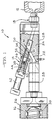
- an injection molding machine 10 shown in Figure 1 which injects molten plastic, or melt, into a mold 12 for forming plastic products.
- the machine 10 provides a sequential two step shut off and compression action through the use of a pressure assist nozzle 14 incorporating a unique combination shut off sleeve and plunger.
- the injection molding machine 10 includes an extruder 16 which receives plastic shot from any convenient storage device, such as a hopper (not shown).
- the extruder 16 operates to plasticize the shot into melt and deliver the melt to an extruder nozzle 18 which is suitable for further delivering the melt to one or more molds 12.
- the extruder 16 can be of any suitable form, such as the screw thread 20 illustrated in Figure 1.
- the extruder is provided with heating elements 26, generally shown as heating bands in Figure 1.
- the extruder nozzle 18 is in fluidic communication with the extruder 16 via a fluidic passage 22.
- the fluidic passage 22 resides within a housing 24 which is mounted between the extruder 16 and the extruder nozzle 18.
- the housing 24 contains the pressure assist nozzle 14 which constitutes the preferred embodiment of the present invention. Similar to the extruder 16, the housing 24 is provided with heating elements 28 to maintain the melt in a fluid state.
- a fitted sleeve 48 defines a valve bore 30 as a portion of the fluidic passage 22 within the housing 24.
- an aperture 32 which provides fluidic communication between the extruder 16 and the extruder nozzle 18.
- the valve bore 30, as defined by the fitted sleeve 48 extends outside the flow path of the fluidic passage 22 to the exterior of the housing 24 to form a plunger bore 34. Accordingly, as seen in Figure 1, the plunger bore 34 constitutes that portion of the valve bore 30 between the aperture 32 and the exterior surface of the housing 24.
- the fluidic passage 22 and the portion of the valve bore 30 which resides within the flow path of the fluidic passage define a finite internal volume between the extruder 16 and the extruder nozzle 18.
- Attached to the housing 24 is an actuator support 38 located coaxial with the plunger bore 34 and the valve bore 30.
- a plunger 44 is reciprocated by way of a hydraulic actuating cylinder 42 mounted to the actuator support 38.
- the plunger 44 reciprocates between an extend position and a retract position.
- Figures 1 and 2 illustrate the retracted position of the plunger 44
- Figure 4 illustrates the extend position of the plunger 44.
- the plunger 44 is threaded into a sleeve end 46 extending toward the plunger bore 34 and the valve bore 30.
- annular sleeve 36 is attached to the sleeve end 46 so that it is reciprocable between the plunger bore 34 and the valve bore 30 when the plunger 44 is stroked between the retract and extend positions.
- the length of the annular sleeve 36 is such that, when in the retract position, the annular sleeve 36 does not extend beyond the aperture 32, as seen in Figures 1 and 2.
- the length of the annular sleeve 36 must be sufficient such that, when in an intermediate position between the retract and extend positions, the annular sleeve 36 closes the aperture 32, as seen in Figure 3.
- a plunger piston 50 reciprocally resides within an annular sleeve bore 40 of the annular sleeve 36.
- the travel of the plunger piston 50 is determined by a radially fixed pin 52 which traverses a pair of corresponding slots 54 and 56 in the annular sleeve 36 and fitted sleeve 48, respectively.
- the slot 56 within the fitted sleeve 48 acts to keep the plunger piston 50 within the valve bore 30 of the housing 24 at all times.
- the slot 54 is positioned longitudinally within the annular sleeve 36 such that the end of the slot 54 acts as an abutment 58, urging the plunger piston 50 into the flow path of the fluidic passage 22 when the annular sleeve 36 is between its intermediate position, as shown in Figure 3, and its extend position, as shown in Figure 4.
- the plunger piston 50 As the plunger piston 50 enters the flow path of the fluidic passage 22, the plunger piston 50 displaces a corresponding portion of the internal volume of the fluidic passage 22. In effect, the plunger piston 50 acts to reduce the original internal volume of the fluidic passage 22, compressing the melt between the aperture 32 and the molds 12.
- the extruder 16 In operation, at the start of a cycle the extruder 16 is provided with a quantity of plastic shot (not shown). The extruder 16 plasticizes the plastic shot to form melt (not shown). The extruder 16 simultaneously rotates and plunges to transport the melt to the fluidic passage 22. At this time, the plunger 44 is in its retract position within the plunger bore 34, as best seen in Figure 2. Consequently, the annular sleeve 36 resides partially in that portion of the valve bore designated as the plunger bore 34. The plunger piston 50 resides entirely within the annular sleeve bore 40 of the annular sleeve 36, which in turn resides within the plunger bore 34.
- a significant advantage of the injection molding machine 10 described above is that the pressure assist nozzle 14, comprised of the annular sleeve 36 and the plunger piston 50, performs a two step shut off and compression action.
- the annular sleeve 36 provides the shut off action to interrupt flow between the extruder 16 and the molds 12 when it closes the aperture 32, while the plunger piston 50 provides the compression action upon the melt when it is stroked into the flow path of the fluidic passage 22 so as to reduce the internal volume of the fluidic passage 22.
- the design of the pressure assist nozzle 14 also provides a more compact apparatus with fewer parts than similar injection molding machines heretofore known in the prior art which provides similar shut off and compression operations.
- a significant advantage of the present invention is that the plunger piston 50 acts to compress and pressurize the melt within the injection manifold 18 and the molds 12 when the plunger piston 50 is traversed from the intermediate position to the extend position.
- the pin 52 of the plunger piston 50 is positioned with respect to the abutment 58 of the annular sleeve 36 so that the plunger piston 50 begins to compress the melt immediately following the closing of the aperture 32 by the annular sleeve 36.
Abstract
Description
- The present invention generally relates to injection molding machines for forming plastic products. More specifically, this invention relates to an injection molding machine having a pressure assist nozzle which operates to compress the molten plastic within the mold and shut off the flow of molten plastic to the injection mold.
- Injection molding machines are widely used to produce plastic products having geometries with varying degrees of complexity. Injection molding machines are typically composed of an extruder, an injection manifold which is provided with molten plastic by the extruder and one or more injection molds which are fed the molten plastic, or melt, by the injection manifold. The extruder is typically provided with solid plastic shot or pellets through a gravity-fed hopper or the like. The plastic shot is plasticized within the extruder by way of heating elements within the extruder's walls. The extruder, through a plunging action or a rotating screw thread action or a combination of both, then operates to provide the injection manifold with a desired quantity of the melt. U. S. Patent No. 3,335,457, typifies a common form of extruder which uses a reciprocating screw to deliver the melt to the manifold.
- From the above it can be readily seen that it is desirable to achieve sufficient mold fill with the melt such that voids are prevented within the mold. Generally this requires an external pressure or displacement source which insures that the melt is sufficiently compresses with the mold throughout the fill and cooling processes. In addition, by providing pressure within the mold and manifold, voids created by shrinkage during cooling are also avoided.
- In many typical injection molding processes, the extruder performs the function of compressing the melt within the mold. However, a disadvantage of this method is that the use of the extruder to insure sufficient fill of the mold prevents the extruder from preparing for the next plasticizing cycle. Therefore, it has been suggested in the art to provide an additional mechanism between the extruder and the mold to perform the compression step. An example of such a device is illustrated in U. S. Patent No. Re. 28,721 to Farrell. Farrell teaches the use of separate shut off and pressurizing mechanisms which operate sequentially by way of a three way valve. The three way valve closes a passage between the extruder and the mold to stop the flow of melt, and then subsequently puts the mold in communication with an accumulator which pressurizes the melt within the mold. A disadvantage of the device taught by Farrell is the requirement for two separate mechanisms to accomplish the shut off and pressurization operations, resulting in more parts and a less compact injection molding machine.
- In addition to the above, it is also important for economical reasons to supply to the molds the necessary quantity of melt to sufficiently fill the molds, and no more. When an excessive amount of melt is provided to the molds, flash is formed between the mold halves which must be removed for aesthetic and/or functional reasons. When an insufficient amount of melt is provided to the molds, voids form within the molds, again negatively affecting the final product aesthetically or functionally. The development of voids is aggravated because the melt shrinks as it cools within the mold.
- For purposes of minimizing waste which occurs as mold flash between the mold halves, it is important in injection molding processes to shut off the flow of the melt to prevent excessive melt from being introduced into the mold. Consequently, a device for stopping the flow from the extruder to the mold is typically used to allow a predetermined quantity of melt to flow from the extruder. The quantity of melt is metered to avoid excessive melt from being injected into the mold and, accordingly, mold flash that accounts for waste is minimized.
- Variations of this basic concept are embodied in U. S. Patent No. 4,412,807 to York and U. S. Patent No. 2,862,241 to DeMattia. York provides a shut off valve which is especially adapted to prevent weld lines from forming within the melt which remains within the injection molding machine between molding operations. DeMattia goes a step further by teaching the use of a spring loaded plunger which, upon the closing of a shut off valve, retracts to accommodate any excess melt, thereby reducing mold flash. Another example of a shut off valve used in the prior art is illustrated in U. S. Patent No. 4,155,969 to Hendry which uses a shut off valve in the operation of a two step injection process.
- From the above discussion it can be readily appreciated that the prior art does not disclose an injection molding machine which provides the advantages of both the shut off operation and the pressurizing operation all within one mechanism. In particular, the prior art does not provide a valve mechanism that acts to close the flow of the melt to the mold while also, by means of its operation, acts to maintain pressure within the mold to prevent voids from forming.
- Accordingly, what is needed is an injection molding machine that is adapted to inject a predetermined quantity of melt into a mold, maintain pressure in the mold in a manner that prevents voids from forming within the melt, while also reducing extruder cycle time. In addition, what is needed is such a machine which provides both operations within one valve body to reduce the number of components required to perform the operation and to simplify manufacture and assembly of such an injection molding machine.
- According to the present invention there is provided an injection apparatus for use in injection molding plastic products. The apparatus has an extruder device which operates to plasticize plastic shot received from a storage device, such as a hopper. The extruder then transfers the melt to a nozzle which feeds one or more molds. The extruder is in fluidic communication with the nozzle via a fluidic passage.
- A bore extends into the passage to define a portion of the passage between the extruder and the nozzle. The bore has an aperture within a side wall which acts as a valve opening within the passage which, when closed, interrupts flow between the extruder and the nozzle. An annular sleeve is reciprocated within the bore by an actuating device. The annular sleeve is actuated between a retract position, in which the annular sleeve is withdrawn from the passage, and an extend position, in which the annular sleeve is projected into the passage in a direction toward the nozzle. When actuated from the retract position to an intermediate position between the retract and extend position, the annular sleeve closes the aperture in the bore, thereby blocking communication between the extruder and the nozzle.
- A plunger piston reciprocally resides within the annular sleeve. The plunger piston is held in a retracted position by the annular sleeve while the annular sleeve is in its retract position. When the annular sleeve has been actuated to close the aperture and thereby stop the flow of melt between the extruder and the nozzle, the plunger piston becomes coupled with the annular sleeve and accompanies the annular sleeve as it continues toward the extend position. By so doing, the plunger piston acts to reduce the internal volume of the passage between the aperture and the nozzle, thereby compressing the melt within the molds.
- According to a preferred aspect of this invention, the annular sleeve operates to close the aperture once the extruder displaces a predetermined volume of melt, thereby preventing further displacement of melt from the extruder. As a result, the volume of melt necessary to fill the mold or molds can be delivered accurately. Once the necessary volume of melt is delivered, the annular sleeve closes the aperture to stop the flow of melt, avoiding the waste associated with excess melt being delivered to the mold.
- In addition, a significant advantage of the present invention is that following the closure of the aperture, the plunger piston acts to compress and pressurize the melt within the nozzle and the mold to prevent the formation of voids within the mold.
- Accordingly, it is an object of the present invention to provide an injection molding machine which is capable of accurately delivering a predetermined quantity of melt to a mold through the use of an annular sleeve operating as a shut off valve.
- It is a further object of this invention that such an injection molding machine be capable of preventing voids from forming in the melt injected into the mold through use of a plunger piston operating as a pressurizing device.
- It is still a further object of this invention that such an injection molding machine combine the functions of the shut off valve and the pressuring device within a pressure assist nozzle to simplify the operational aspects of the injection molding machine.
- It is yet another object of this invention that such a pressure assist nozzle provide for a more compact apparatus with fewer parts.
- Other objects and advantages of this invention will be more apparent after a reading of the following detailed description taken in conjunction with the drawings provided.
-
- Figure 1 is a foreshortened fragmentary partial cross-sectional view of an injection molding machine with pressure assist nozzle in accordance with a preferred embodiment of this invention;
- Figure 2 is a detailed cross-sectional illustration of the pressure assist nozzle of Figure 1 in a retracted flow position;
- Figure 3 is a detailed cross-sectional illustration of the pressure assist nozzle of Figure 1 in an intermediate shut off position in accordance; and
- Figure 4 is a detailed cross-sectional illustration of the pressure assist nozzle of Figure 1 in an extended pressurizing position.
- In a preferred embodiment of this invention, an
injection molding machine 10, shown in Figure 1, is provided which injects molten plastic, or melt, into amold 12 for forming plastic products. Themachine 10 provides a sequential two step shut off and compression action through the use of a pressure assistnozzle 14 incorporating a unique combination shut off sleeve and plunger. - The
injection molding machine 10 includes anextruder 16 which receives plastic shot from any convenient storage device, such as a hopper (not shown). Theextruder 16 operates to plasticize the shot into melt and deliver the melt to anextruder nozzle 18 which is suitable for further delivering the melt to one ormore molds 12. Theextruder 16 can be of any suitable form, such as thescrew thread 20 illustrated in Figure 1. To plasticize the shot and maintain the melt in a fluid form during its progress through theinjection molding machine 10, the extruder is provided withheating elements 26, generally shown as heating bands in Figure 1. - The
extruder nozzle 18 is in fluidic communication with theextruder 16 via afluidic passage 22. Thefluidic passage 22 resides within ahousing 24 which is mounted between theextruder 16 and theextruder nozzle 18. Thehousing 24 contains the pressure assistnozzle 14 which constitutes the preferred embodiment of the present invention. Similar to theextruder 16, thehousing 24 is provided withheating elements 28 to maintain the melt in a fluid state. - A fitted
sleeve 48 defines a valve bore 30 as a portion of thefluidic passage 22 within thehousing 24. Within corresponding side walls of the fittedsleeve 48 and the valve bore 30 there is anaperture 32 which provides fluidic communication between theextruder 16 and theextruder nozzle 18. The valve bore 30, as defined by the fittedsleeve 48, extends outside the flow path of thefluidic passage 22 to the exterior of thehousing 24 to form a plunger bore 34. Accordingly, as seen in Figure 1, the plunger bore 34 constitutes that portion of the valve bore 30 between theaperture 32 and the exterior surface of thehousing 24. Thefluidic passage 22 and the portion of the valve bore 30 which resides within the flow path of the fluidic passage define a finite internal volume between theextruder 16 and theextruder nozzle 18. - Attached to the
housing 24 is anactuator support 38 located coaxial with the plunger bore 34 and the valve bore 30. Aplunger 44 is reciprocated by way of ahydraulic actuating cylinder 42 mounted to theactuator support 38. Theplunger 44 reciprocates between an extend position and a retract position. Figures 1 and 2 illustrate the retracted position of theplunger 44, whereas Figure 4 illustrates the extend position of theplunger 44. Theplunger 44 is threaded into asleeve end 46 extending toward the plunger bore 34 and the valve bore 30. When thehydraulic actuating cylinder 42 strokes theplunger 44 to its extend positioned, as shown in Figure 4, thesleeve end 46 extends into the plunger bore 34. - An
annular sleeve 36 is attached to thesleeve end 46 so that it is reciprocable between the plunger bore 34 and the valve bore 30 when theplunger 44 is stroked between the retract and extend positions. The length of theannular sleeve 36 is such that, when in the retract position, theannular sleeve 36 does not extend beyond theaperture 32, as seen in Figures 1 and 2. However, the length of theannular sleeve 36 must be sufficient such that, when in an intermediate position between the retract and extend positions, theannular sleeve 36 closes theaperture 32, as seen in Figure 3. - A
plunger piston 50 reciprocally resides within an annular sleeve bore 40 of theannular sleeve 36. The travel of theplunger piston 50 is determined by a radially fixedpin 52 which traverses a pair ofcorresponding slots annular sleeve 36 and fittedsleeve 48, respectively. Theslot 56 within the fittedsleeve 48 acts to keep theplunger piston 50 within the valve bore 30 of thehousing 24 at all times. Theslot 54 is positioned longitudinally within theannular sleeve 36 such that the end of theslot 54 acts as anabutment 58, urging theplunger piston 50 into the flow path of thefluidic passage 22 when theannular sleeve 36 is between its intermediate position, as shown in Figure 3, and its extend position, as shown in Figure 4. As theplunger piston 50 enters the flow path of thefluidic passage 22, theplunger piston 50 displaces a corresponding portion of the internal volume of thefluidic passage 22. In effect, theplunger piston 50 acts to reduce the original internal volume of thefluidic passage 22, compressing the melt between theaperture 32 and themolds 12. - In operation, at the start of a cycle the
extruder 16 is provided with a quantity of plastic shot (not shown). Theextruder 16 plasticizes the plastic shot to form melt (not shown). Theextruder 16 simultaneously rotates and plunges to transport the melt to thefluidic passage 22. At this time, theplunger 44 is in its retract position within the plunger bore 34, as best seen in Figure 2. Consequently, theannular sleeve 36 resides partially in that portion of the valve bore designated as the plunger bore 34. Theplunger piston 50 resides entirely within the annular sleeve bore 40 of theannular sleeve 36, which in turn resides within the plunger bore 34. - After a predetermined period of time in which, determined through prior calibration, a desired quantity of melt has been transported from the
extruder 16 through thefluidic passage 22 andextruder nozzle 18 to themolds 12. At such a time a signal is provided to thehydraulic actuating cylinder 42 to stroke theplunger 44 from its retract position towards the valve bore 30 and the extend position. Consequently, theannular sleeve 36 also is stroked, eventually arriving at its intermediate position in which theannular sleeve 36 closes theaperture 32 to stop the flow of melt, as shown in Figure 3. At this time theplunger piston 50 remains within the annular sleeve bore 40 in the area of plunger bore 34 because thepin 52 has yet to encounter theabutment 58 within theslot 54 of theannular sleeve 36. - As the
hydraulic actuating cylinder 42 continues to stroke theplunger 44 towards the extend position, thepin 52 abuts theabutment 58 of theannular sleeve 36, thereby urging theplunger piston 50 into the flow path of thefluidic passage 22. Theplunger 44 continues to be stroked until theplunger piston 50 meets sufficient resistance from the melt trapped between the now closedaperture 32 and themolds 12. Theplunger 44,annular sleeve 36 andplunger piston 50 ultimately reach the extend position, illustrated in Figure 4. The entire pressure assistnozzle 14 is then returned to the retract position, illustrated in Figures 1 and 2, by a reverse order of the above described operation. - A significant advantage of the
injection molding machine 10 described above is that the pressure assistnozzle 14, comprised of theannular sleeve 36 and theplunger piston 50, performs a two step shut off and compression action. Theannular sleeve 36 provides the shut off action to interrupt flow between theextruder 16 and themolds 12 when it closes theaperture 32, while theplunger piston 50 provides the compression action upon the melt when it is stroked into the flow path of thefluidic passage 22 so as to reduce the internal volume of thefluidic passage 22. The design of the pressure assistnozzle 14 also provides a more compact apparatus with fewer parts than similar injection molding machines heretofore known in the prior art which provides similar shut off and compression operations. - In addition, a significant advantage of the present invention is that the
plunger piston 50 acts to compress and pressurize the melt within theinjection manifold 18 and themolds 12 when theplunger piston 50 is traversed from the intermediate position to the extend position. Thepin 52 of theplunger piston 50 is positioned with respect to theabutment 58 of theannular sleeve 36 so that theplunger piston 50 begins to compress the melt immediately following the closing of theaperture 32 by theannular sleeve 36. - While the invention has been described in terms of a preferred embodiment, it is apparent that other forms could be adopted by one skilled in the art. Accordingly, the scope of the invention is to be limited only by the following claims.
Claims (16)
- An injection apparatus comprising:
extruder means;
nozzle means in fluidic communication with said extruder means via a fluidic passage, said fluidic passage defining an internal volume, said fluidic passage having a bore therein, said bore defining an aperture within said fluidic passage;
an annular sleeve reciprocally residing within said bore, said annular sleeve being reciprocated between an extend position and a retract position by actuating means, said annular sleeve closing said aperture when said annular sleeve is in an intermediate position between said retract position and said extend position; and
a plunger piston reciprocally residing within said annular sleeve, said plunger piston having engagement means in communication with said annular sleeve, said engagement means acting to couple said plunger piston with said annular sleeve as said annular sleeve traverses from said intermediate position to said extend position, said plunger piston thereby acting to reduce said internal volume of said fluidic passage. - An injection molding apparatus as claimed in claim 1, wherein said bore defines a passage portion and a plunger portion, said annular sleeve reciprocating within both said passage portion and said plunger portion, said aperture being located in a wall of said passage portion.
- An injection apparatus as claimed in claim 1, wherein said annular sleeve has an abutment means in communication with said engagement means, said abutment means engaging said engagement means when said annular sleeve is at said intermediate position.
- An injection apparatus as claimed in claim 1, wherein said extruder means is operable to displace a fluidic injection material from said extruder means through said fluidic passage to said nozzle means.
- An injection apparatus as claimed in claim 4, wherein said actuating means traverses said annular sleeve from said retract position to said intermediate position after said extruder means displaces a predetermined quantity of said fluidic injection material, said annular sleeve thereby closing said aperture to prevent further displacement of said fluidic injection material from said extruder means.
- An injection apparatus as claimed in claim 5, wherein said plunger piston acts to compress and pressurize said fluidic injection material within said nozzle means while said plunger piston is being traversed with said annular sleeve from said intermediate position to said extend position.
- An injection molding apparatus providing a two step shut off and compression action upon a molten plastic, said injection mold apparatus comprising:
an extruder;
an extruder nozzle in fluidic communication with said extruder via a fluidic passage, said fluidic passage defining an internal volume between said extruder and said extruder nozzle;
a bore defining a portion of said fluidic passage, said bore having an aperture in a side wall thereof, said aperture providing fluidic communication between said extruder and said extruder nozzle therethrough, said bore extending beyond said fluidic passage to form a plunger bore;
a plunger reciprocally residing within said plunger bore, said plunger being reciprocated by actuating means between an extend position and a retract position, said plunger having a plunger end extending toward said bore when said plunger is in said extend position;
an annular sleeve attached to said plunger end, said annular sleeve being reciprocable within said plunger bore and said bore by said plunger, said annular sleeve closing said aperture of said bore when said plunger is in an intermediate position between said retract position and said extend position, said annular sleeve having abutment means; and
a plunger piston reciprocally residing within said annular sleeve, said plunger piston having engagement means in communication with said abutment means of said annular sleeve, said engagement means engaging said abutment means thereby urging said plunger piston into said bore while said plunger traverses from said intermediate position to said extend position, said plunger piston thereby acting to reduce said internal volume of said fluidic passage. - An injection molding apparatus as claimed in claim 7, wherein said annular sleeve performs a shut off action and said plunger piston performs a compression action to constitute said two step shut off and compression action.
- An injection molding apparatus as claimed in claim 7, wherein said actuating means is a hydraulic actuating cylinder.
- An injection molding apparatus as claimed in claim 7, further comprising a housing mounted between said extruder and said injection manifold, said fluidic passage and said bore being formed within said housing.
- An injection molding apparatus as claimed in claim 10, further comprising heating elements for heating said housing.
- An injection molding apparatus as claimed in claim 10, further comprising an actuating housing, said actuating housing being mounted to said housing, said plunger bore being formed in part within said actuator housing.
- An injection molding apparatus as claimed in claim 7, wherein said extruder is operable to displace said molten plastic from said extruder through said fluidic passage to said extruder nozzle.
- An injection molding apparatus as claimed in claim 13, wherein said actuating means traverses said plunger from said retract position to said intermediate position after said extruder displaces a predetermined volume of molten plastic, said annular sleeve thereby closing said aperture to prevent further displacement of said molten plastic from said extruder.
- An injection molding apparatus as claimed in claim 13, wherein said plunger piston acts to compress and pressurize said molten plastic within said extruder nozzle while said plunger piston is being traversed with said annular sleeve from said intermediate position to said extend position.
- An injection molding apparatus as claimed in claim 7, wherein said engagement means is a pin extending radially from said plunger piston and said abutment means is formed on a longitudinal slot within said annular sleeve, said pin traversing said slot between said retract and said intermediate positions, said pin abutting said abutment means between said intermediate and said extend positions.
Applications Claiming Priority (2)
| Application Number | Priority Date | Filing Date | Title |
|---|---|---|---|
| US07/605,078 US5071341A (en) | 1990-10-24 | 1990-10-24 | Injection molding machine with pressure assist nozzle |
| US605078 | 2000-06-28 |
Publications (2)
| Publication Number | Publication Date |
|---|---|
| EP0482743A2 true EP0482743A2 (en) | 1992-04-29 |
| EP0482743A3 EP0482743A3 (en) | 1992-06-17 |
Family
ID=24422169
Family Applications (1)
| Application Number | Title | Priority Date | Filing Date |
|---|---|---|---|
| EP19910306770 Ceased EP0482743A3 (en) | 1990-10-24 | 1991-07-25 | Injection molding machine with pressure assist nozzle |
Country Status (3)
| Country | Link |
|---|---|
| US (1) | US5071341A (en) |
| EP (1) | EP0482743A3 (en) |
| CA (1) | CA2048106A1 (en) |
Cited By (2)
| Publication number | Priority date | Publication date | Assignee | Title |
|---|---|---|---|---|
| EP0583857A1 (en) * | 1992-07-17 | 1994-02-23 | MANNESMANN Aktiengesellschaft | Method and apparatus for exerting a packing pressure on injection moulding materials |
| DE10346877A1 (en) * | 2003-10-09 | 2005-05-19 | Krauss-Maffei Kunststofftechnik Gmbh | Injection molding apparatus for micro-injection molded parts made of liquid silicone rubber or thermoplastics, has nozzle with piston chamber arranged between screw cylinder and mold |
Families Citing this family (9)
| Publication number | Priority date | Publication date | Assignee | Title |
|---|---|---|---|---|
| DE4022530C2 (en) * | 1990-07-16 | 1993-10-21 | Kloeckner Ferromatik Desma | Nozzle for injection molding machines |
| DE4221423C2 (en) * | 1992-06-30 | 2002-06-20 | Sig Corpoplast Gmbh & Co Kg | Method and device for producing objects from thermoplastic material by injection molding |
| FR2695345B1 (en) * | 1992-09-09 | 1994-11-25 | Metals Process Systems | Injection molding machine and use thereof. |
| US5509797A (en) * | 1993-09-30 | 1996-04-23 | Nissei Plastic Industrial Co., Ltd. | Injection apparatus possessing pressure holding device |
| JP2928750B2 (en) * | 1995-09-27 | 1999-08-03 | 日精樹脂工業株式会社 | Packing method in injection molding |
| US6739862B2 (en) * | 2001-03-15 | 2004-05-25 | Robert Franklin Dray | Dual cylinder injection molding apparatus |
| US6527539B1 (en) * | 2000-10-25 | 2003-03-04 | Husky Injection Molding Systems, Ltd. | Injection unit of an injection system |
| JP5535595B2 (en) | 2009-11-25 | 2014-07-02 | 日精エー・エス・ビー機械株式会社 | INJECTION DEVICE AND RESIN INJECTION METHOD |
| CN109177048B (en) * | 2018-09-29 | 2024-03-22 | 苏州松之叶精密机械配件有限公司 | High-precision full-automatic vertical rubber injection molding machine |
Citations (4)
| Publication number | Priority date | Publication date | Assignee | Title |
|---|---|---|---|---|
| GB888448A (en) * | 1960-02-08 | 1962-01-31 | R H Windsor Ltd | Improvements in injection moulding machines |
| DE2061267A1 (en) * | 1970-12-12 | 1972-06-22 | Vox Anton J | Injection moulding machine - with separate injection and plasticising for continuous plasticising |
| DE2614213A1 (en) * | 1976-04-02 | 1977-10-20 | Ver Foerderung Inst Kunststoff | Injection-moulding of thick-walled, large-volume mouldings - by effecting successive pressure impulses during a post-pressure phase, on the compressible moulding cpd. in the mould |
| FR2552701A1 (en) * | 1983-10-04 | 1985-04-05 | Dieffenbacher Gmbh Maschf | INJECTION-TRANSFER PRESS |
Family Cites Families (6)
| Publication number | Priority date | Publication date | Assignee | Title |
|---|---|---|---|---|
| SE126759C1 (en) * | 1947-09-09 | 1949-11-22 | ||
| US2862241A (en) * | 1956-11-30 | 1958-12-02 | Mattia Machine & Tool Co De | Apparatus for the automatic controlled feeding of plastic material |
| US3335457A (en) * | 1964-10-19 | 1967-08-15 | Hoover Ball & Bearing Co | Blow molding machine with continuously rotating reciprocating extruder screw |
| USRE28721E (en) * | 1970-11-25 | 1976-02-24 | Farrell Patent Company | Time saver plastic draw-back valve assembly |
| US4067673A (en) * | 1975-09-02 | 1978-01-10 | Ex-Cell-O Corporation | Apparatus for injection foam molding |
| US4412807A (en) * | 1982-01-28 | 1983-11-01 | The Continental Group, Inc. | Offset flow injection nozzle |
-
1990
- 1990-10-24 US US07/605,078 patent/US5071341A/en not_active Expired - Fee Related
-
1991
- 1991-07-25 EP EP19910306770 patent/EP0482743A3/en not_active Ceased
- 1991-07-30 CA CA002048106A patent/CA2048106A1/en not_active Abandoned
Patent Citations (4)
| Publication number | Priority date | Publication date | Assignee | Title |
|---|---|---|---|---|
| GB888448A (en) * | 1960-02-08 | 1962-01-31 | R H Windsor Ltd | Improvements in injection moulding machines |
| DE2061267A1 (en) * | 1970-12-12 | 1972-06-22 | Vox Anton J | Injection moulding machine - with separate injection and plasticising for continuous plasticising |
| DE2614213A1 (en) * | 1976-04-02 | 1977-10-20 | Ver Foerderung Inst Kunststoff | Injection-moulding of thick-walled, large-volume mouldings - by effecting successive pressure impulses during a post-pressure phase, on the compressible moulding cpd. in the mould |
| FR2552701A1 (en) * | 1983-10-04 | 1985-04-05 | Dieffenbacher Gmbh Maschf | INJECTION-TRANSFER PRESS |
Cited By (3)
| Publication number | Priority date | Publication date | Assignee | Title |
|---|---|---|---|---|
| EP0583857A1 (en) * | 1992-07-17 | 1994-02-23 | MANNESMANN Aktiengesellschaft | Method and apparatus for exerting a packing pressure on injection moulding materials |
| DE10346877A1 (en) * | 2003-10-09 | 2005-05-19 | Krauss-Maffei Kunststofftechnik Gmbh | Injection molding apparatus for micro-injection molded parts made of liquid silicone rubber or thermoplastics, has nozzle with piston chamber arranged between screw cylinder and mold |
| DE10346877B4 (en) * | 2003-10-09 | 2007-02-08 | Krauss-Maffei Kunststofftechnik Gmbh | Apparatus and method for injection molding |
Also Published As
| Publication number | Publication date |
|---|---|
| US5071341A (en) | 1991-12-10 |
| EP0482743A3 (en) | 1992-06-17 |
| CA2048106A1 (en) | 1992-04-25 |
Similar Documents
| Publication | Publication Date | Title |
|---|---|---|
| US5071341A (en) | Injection molding machine with pressure assist nozzle | |
| US6824374B1 (en) | Thermoplastic resin injection molding machine | |
| US6017210A (en) | Apparatus for dwelling in injection molding | |
| US2404559A (en) | Plastic slug forming and feeding mechanism | |
| US4342717A (en) | Injection moulding method and apparatus with mould runner reservoir and shot extension | |
| US4256689A (en) | Injection moulding method and apparatus with mould runner reservoir and shot extension | |
| JPH0790578B2 (en) | Injection unit for injection molding machine | |
| US6488490B1 (en) | Thermoplastic resin injection molding machine with the injecting unit including a rotary pump and torque limiter | |
| US4752201A (en) | Apparatus for injection molding fiber-reinforced thermoset plastic articles | |
| US3401426A (en) | Plastic injection molding machine | |
| US3611503A (en) | Injection molding apparatus for plastic materials | |
| CA2063924C (en) | Improvements in plasticising units for screw injection moulding machines | |
| US3436793A (en) | Injection molding machine | |
| JPH0445867Y2 (en) | ||
| JPH0397517A (en) | Preplastication type injection molding machine | |
| JPS5848114Y2 (en) | Injection molding machine | |
| JPH07214618A (en) | Check ring opening/closing device in injection molding machine | |
| WO2002060671A1 (en) | Injection nozzle | |
| JP3248758B2 (en) | Method of discharging accumulated resin in an injection molding machine | |
| JPS608209B2 (en) | Injection molding machine for two-component mixed curing resin | |
| US6645405B2 (en) | Weighing method in prepla type injection molding machine | |
| JPH0375107A (en) | Resin feeder | |
| JP3359142B2 (en) | Check ring opening and closing device in injection molding machine | |
| JP3014971U (en) | Injection machine injection machine | |
| JP2000000860A (en) | Screw injection device |
Legal Events
| Date | Code | Title | Description |
|---|---|---|---|
| PUAI | Public reference made under article 153(3) epc to a published international application that has entered the european phase |
Free format text: ORIGINAL CODE: 0009012 |
|
| PUAL | Search report despatched |
Free format text: ORIGINAL CODE: 0009013 |
|
| AK | Designated contracting states |
Kind code of ref document: A2 Designated state(s): DE FR GB IT |
|
| AK | Designated contracting states |
Kind code of ref document: A3 Designated state(s): DE FR GB IT |
|
| 17P | Request for examination filed |
Effective date: 19920623 |
|
| 17Q | First examination report despatched |
Effective date: 19940425 |
|
| STAA | Information on the status of an ep patent application or granted ep patent |
Free format text: STATUS: THE APPLICATION HAS BEEN REFUSED |
|
| 18R | Application refused |
Effective date: 19950514 |