EP0482423B1 - Immersion casting pipe for the introduction of molten steel in a continuous casting mould - Google Patents
Immersion casting pipe for the introduction of molten steel in a continuous casting mould Download PDFInfo
- Publication number
- EP0482423B1 EP0482423B1 EP91117179A EP91117179A EP0482423B1 EP 0482423 B1 EP0482423 B1 EP 0482423B1 EP 91117179 A EP91117179 A EP 91117179A EP 91117179 A EP91117179 A EP 91117179A EP 0482423 B1 EP0482423 B1 EP 0482423B1
- Authority
- EP
- European Patent Office
- Prior art keywords
- outflow
- pouring tube
- immersion
- web
- tube according
- Prior art date
- Legal status (The legal status is an assumption and is not a legal conclusion. Google has not performed a legal analysis and makes no representation as to the accuracy of the status listed.)
- Revoked
Links
- 238000007654 immersion Methods 0.000 title claims abstract description 19
- 229910000831 Steel Inorganic materials 0.000 title claims abstract description 18
- 239000010959 steel Substances 0.000 title claims abstract description 18
- 238000005266 casting Methods 0.000 title claims abstract description 15
- 238000009749 continuous casting Methods 0.000 title claims abstract description 4
- 239000002184 metal Substances 0.000 claims abstract description 3
- 239000007788 liquid Substances 0.000 claims description 4
- 238000005406 washing Methods 0.000 description 4
- 238000009826 distribution Methods 0.000 description 3
- 241001295925 Gegenes Species 0.000 description 1
- 230000001154 acute effect Effects 0.000 description 1
- 230000015572 biosynthetic process Effects 0.000 description 1
- 230000002349 favourable effect Effects 0.000 description 1
- 238000009434 installation Methods 0.000 description 1
- 230000001788 irregular Effects 0.000 description 1
- 238000004519 manufacturing process Methods 0.000 description 1
- 238000005507 spraying Methods 0.000 description 1
- 230000007704 transition Effects 0.000 description 1
- 238000011144 upstream manufacturing Methods 0.000 description 1
Images

Classifications
-
- B—PERFORMING OPERATIONS; TRANSPORTING
- B22—CASTING; POWDER METALLURGY
- B22D—CASTING OF METALS; CASTING OF OTHER SUBSTANCES BY THE SAME PROCESSES OR DEVICES
- B22D41/00—Casting melt-holding vessels, e.g. ladles, tundishes, cups or the like
- B22D41/50—Pouring-nozzles
Abstract
Description
Die Erfindung betrifft ein Tauchgießrohr zum Einleiten von Metallschmelze insbesondere flüssigem Stahl in den Eingießbereich einer Stranggießanlage, bestehend aus einem an einem Gießbehälter angeschlossenen Zuflußteil und einem abgeflachten Ausströmteil mit an einem Steg befindlichen Flächen zur Teilung der Zuflußströmung in mindestens zwei Teilströmungen und mit Flächen zur Vereinigung von Teilströmungen vor der Ausströmöffnung.The invention relates to an immersion pouring tube for introducing molten metal, in particular liquid steel, into the pouring region of a continuous casting installation, consisting of an inflow part connected to a casting container and a flattened outflow part with surfaces located on a web for dividing the inflow flow into at least two partial flows and with surfaces for combining Partial flows in front of the outflow opening.
Bei einem durch die DE-A 37 09 188 bekannten Tauchgießrohr ist an dem zylindrischen Rohrteil ein abgeflachtes Endteil mit schlitzartigen Austrittsöffnungen und ein Bodenstück mit erhabener Innenkontur angeordnet. Das Bodenstück hat in Richtung der Ausströmöffnungen eine größere Ausdehnung als der Abstand der die Ausströmöffnungen nach oben begrenzenden Wandungen.In a dip tube known from DE-A 37 09 188, a flattened end part with slot-like outlet openings and a base piece with a raised inner contour are arranged on the cylindrical tube part. The base piece has a greater extent in the direction of the outflow openings than the distance between the walls delimiting the outflow openings upwards.
Dieses bekannte Gießrohr ist trotz aufwendiger Herstellung der hohen Beanspruchung beim Stahlstranggießen nicht mit der erforderlichen Betriebssicherheit und Standzeit gewachsen. Aus den schmalen Ausströmöffnungen tritt die Stahlschmelze gebündelt mit zu hoher kinetischer Energie aus, wodurch es insbesondere in einer schmalen Stahlbandgießkokille zu Auswaschungen an der noch dünnen Strangschale und zur Ausbildung einer Stauwelle vor den Schmalseitenwänden kommt. Darüber hinaus kommt es bei Verwendung des bekannten Gießrohres aufgrund ungleicher Strömungsverteilung innerhalb der Kokille zur Ausbildung einer unregelmäßigen Oberflächenstruktur.This well-known pouring tube has not grown with the required operational reliability and service life despite the complex production of the high stresses in continuous steel casting. The molten steel emerges from the narrow outflow openings with excessive kinetic energy, which leads to washing out of the still thin strand shell and the formation of a damming wave in front of the narrow side walls, particularly in a narrow steel strip casting mold. In addition, when using the known pouring tube, an irregular surface structure is formed due to the uneven flow distribution within the mold.
Bei einem anderen durch die WO 89/12519 bekannten Tauchgießrohr laufen die Einzelströmungen in einem spitzen Winkel zusammen, weshalb die Stahlschmelze mit noch zu hoher kinetischer Energie in den Kokillenraum austritt.In another immersion pouring tube known from WO 89/12519, the individual flows converge at an acute angle, which is why the molten steel emerges into the mold space with kinetic energy that is still too high.
Aufgabe der Erfindung ist die Schaffung eines betriebssicheren Tauchgießrohres zum Eingießen von Stahlschmelze in eine Kokille insbesondere zum Gießen von Stahlbändern, wobei aufgrund besserer Strömungsverteilung eine Stauwelle in der Badspiegeloberfläche und eine Auswaschung der sich bildenden Strangschale durch den flüssigen Stahl stark vermindert und ein Gießstrang insbesondere Stahlband mit gleichmäßig fehlerfreier Oberfläche erzielt wird. Darüber hinaus soll beim Angießvorgang das Hochspritzen und Anbacken von Stahlschmelze an den Kokillenwänden vermieden werden.The object of the invention is to provide a reliable immersion pouring tube for pouring molten steel into a mold, in particular for casting steel strips, whereby due to better flow distribution, a build-up wave in the surface of the bath surface and a washing out of the strand shell that is formed by the liquid steel are greatly reduced and a casting strand, in particular steel strip, is provided uniformly flawless surface is achieved. In addition, the spraying and baking of molten steel on the mold walls should be avoided during the casting process.
Die Erfindung basiert auf der Erkenntnis, daß die Ursache für eine ungleiche, instabile Schmelzenverteilung innerhalb der Kokille zu hohe und ungleiche Austrittsgeschwindigkeit über die Austrittsquerschnitte ist.The invention is based on the knowledge that the cause of an uneven, unstable melt distribution within the mold is too high and uneven exit velocity over the exit cross-sections.
Dadurch, daß die Austrittsgeschwindigkeit im unteren Teil des Austrittsschlitzes am größten ist, bilden sich unterhalb der Ausströmöffnung je ein starker Wirbel und entsprechende aufwärts gerichtete Ausgleichsströmungen vor der Schmalseitenwand aus, die zu einer Stauwelle auf dem Badspiegel führen.Because the exit speed is greatest in the lower part of the exit slot, a strong vortex and corresponding upward equalizing flows form in front of the narrow side wall below the outflow opening, which lead to a ram wave on the bath level.
Erfindungsgemäß wird die gestellte Aufgabe dadurch gelöst, daß der Ausströmteil Flächen zur Umleitung der Teilströmungen bis in zueinander entgegengesetzten Richtungslagen vor der Ausströmöffnung aufweist.According to the invention, the object is achieved in that the outflow part has surfaces for diverting the partial flows up to opposite directions in front of the outflow opening.
Durch das direkte Aufeinandertreffen der Teilströmungen innerhalb des Tauchgießrohres kommt es zum gegenseitigen Energieausgleich, so daß der flüssige Stahl aus den Ausströmöffnungen mit geringerer Geschwindigkeit austritt. Auf diese Weise werden nachteilige Querströmungen mit oberen Stauwellen und Auswaschungen der Strangschale vermieden und ein Produkt mit fehlerfreier Oberfläche erzielt.Due to the direct encounter of the partial flows within the immersion nozzle, there is mutual energy compensation, so that the molten steel emerges from the outflow openings at a lower speed. In this way, disadvantageous cross currents with upper damming waves and washing out of the strand shell are avoided and a product with a flawless surface is achieved.
Gemäß einem weiteren Merkmal der Erfindung weist der Ausströmteil im Abstand zum Steg seitliche Leitflächen, Bodenflächen und und der Stegunterseite über der Ausströmöffnung eine Leitfläche auf.According to a further feature of the invention, the outflow part has lateral guide surfaces, bottom surfaces and and the underside of the web above the outflow opening at a distance from the web.
Eine besonders vorteilhafte Ausgestaltung der Erfindung wird darin gesehen, daß die Stegleitfläche im Abstand a = 50 - 150 mm vor einem mit der Ausströmsöffnung versehenen Boden angeordnet ist.A particularly advantageous embodiment of the invention is seen in the fact that the web sliding surface is arranged at a distance a = 50-150 mm in front of a floor provided with the outflow opening.
Die Weite w der Ausströmöffnung entspricht mindestens dem zweifachen Abstand a der Stegleitfläche vom Boden.The width w of the outflow opening corresponds to at least twice the distance a of the web sliding surface from the floor.
Besonders günstige Ausströmbedingungen ergeben sich, wenn die Breitwände im Bereich der Ausströmöffnungen um maximal 0,5 · a kürzer sind als im Bereich des Bodens.Particularly favorable outflow conditions result if the wide walls in the area of the outflow openings are a maximum of 0.5 · a shorter than in the area of the floor.
Die Breite des Ausströmteiles parallel zu den Breitwänden beträgt zwischen 350 und 550 mm.The width of the outflow part parallel to the wide walls is between 350 and 550 mm.
In der Zeichnung ist ein Ausführungsbeispiel mit Merkmalen und Vorteilen der Erfindung dargestellt. Es zeigen
- Fig. 1
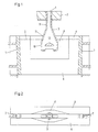
- schematisch eine Dünnbrammengießmaschine mit in den erweiterten Eingießbereich hineinragendem Tauchgießrohr im Längsschnitt,
- Fig. 2
- eine Draufsicht zu Fig. 1,
- Fig. 3
- einen Längsschnitt durch das Tauchgießrohr parallel zu den Breitwänden,
- Fig. 4
- einen Längsschnitt durch das Tauchgießrohr quer zu den Breitwänden,
- Fig. 5
- eine Ansicht des Tauchgießrohres gegen die Ausströmöffnung
und - Fig. 6
- einen Querschnitt des Tauchgießrohres gemäß der Linie VI - VI in Fig. 4.
- Fig. 1
- schematically shows a thin slab casting machine with a dip pipe protruding into the extended pouring area in longitudinal section,
- Fig. 2
- 2 shows a top view of FIG. 1,
- Fig. 3
- a longitudinal section through the immersion pouring tube parallel to the wide walls,
- Fig. 4
- a longitudinal section through the immersion pouring tube transverse to the wide walls,
- Fig. 5
- a view of the immersion pouring tube against the outflow opening
and - Fig. 6
- 3 shows a cross section of the immersion pouring tube along the line VI-VI in FIG. 4.
Gemäß Figur 1 befindet sich am Bodenauslaß 1 eines Gießbehälters 2 ein Tauchgießrohr 3, das mit seinem unteren Ende in eine Stahlbandgießkokille 4 bis unter den Gießspiegel 5 ragt. Die Stahlbandgießkokille 4 besteht aus zwei gekühlten Breitseitenwänden 6 und zwei zwischen diesen verstellbar angeordneten Schmalseitenwänden 7. Die Breitseitenwände 6 bilden zur Aufnahme des Tauchgießrohres 3 einen erweiterten Eingießbereich 8, der sich über einen Teil der Kokillenhöhe erstreckt.According to FIG. 1, there is an
Das erfindungsgemäße Tauchgießrohr 3 besteht aus einem Anschlußstutzen 9, einem flachen Ausströmteil 10 und einem Übergangsteil 11. Der Ausströmteil 10 wird von zwei Breitwänden 12, zwei Leitwänden 13 und einem Boden 14 gebildet. In dem Boden befindet sich eine Ausströmöffnung 15. Oberhalb der Ausströmöffnung 15 befindet sich ein die Breitwände 12 verbindender Steg 16.The
Der Steg 16 hat an der Oberseite zwei Teilflächen 17, die im Ausführungsbeispiel dachartig zueinander geneigt sind. Durch die Teilflächen 17 oder z.B. eine gewölbte Oberseite wird die von oben zulaufende Strömung 18 in zwei Teilströmungen 19 getrennt.The
Die Teilströmungen 19 werden an den Leitwänden 13 und dem Boden 14 zweifach umgelenkt, so daß sie unterhalb der Leitfläche 20 des Steges 16 aufeinandertreffen, wobei erhebliche Strömungsenergie verzehrt wird. Infolgedessen tritt aus der Ausströmöffnung 15 ein Strom flüssigen Stahls geringer Geschwindigkeit aus, so daß eine Stauwelle und Auswaschungen der Strangschale vermieden werden.The
Die untere Leitfläche 20 des Steges 16 bestimmt die Höhe der seitlichen Strömungsquerschnitte, d.h. den Abstand a der Leitfläche 20 vom Boden 14. Dieser kann vorteilhaft 50 bis 150 mm betragen.The
Die Breitwände 12 sind im Bereich der Ausströmöffnungen 15 kürzer als im Bereich des Bodens 14.The
Die Breite b des Ausströmteils 10 kann zwischen 350 - 550 mm betragen.The width b of the
Die Weite w der Ausströmöffnung 15 soll mindestens das Doppelte des Abstandes a der Leitfläche 20 vom Boden 14 betragen.The width w of the
Die Erfindung ist nicht auf das dargestellte Ausführungsbeispiel beschränkt.The invention is not restricted to the exemplary embodiment shown.
Claims (6)
- Immersion pouring tube for the introduction of molten metal, particularly liquid steel, into the pouring-in region of a continuous casting plant, consisting of an inflow part (9, 11) connected to a casting vessel (2) and a flattened outflow part (10) with surfaces (17), which are disposed at a web (16), for division of the inward flow into at least two partial flows (19) and with surfaces (13, 14) for reuniting the partial flows ahead of the outflow openings (15), characterised thereby that the outflow part (10) has surfaces (13, 14, 20) for diversion of the partial flows (19) until in mutually opposed direction positions in front of the outflow opening (15).
- Immersion pouring tube according to claim 1, characterised thereby that the outflow part (10) has lateral guide surfaces (13) and base surfaces (14) at a spacing from the web (16) and a guide surface (20) at the underside of the web and over the outflow opening (15).
- Immersion pouring tube according to claims 1 and 2, characterised thereby that the guide surface (20) is arranged at a spacing (a = 50 to 150 millimetres) in front of a base (14) provided with the outflow opening (15).
- Immersion pouring tube according to claims 1 to 3, characterised thereby that the width w of the outflow opening (15) corresponds to at least twice the spacing a of the web guide surface (20) from the base (14).
- Immersion pouring tube according to claims 1 to 4, characterised thereby that the wide walls (12) are shorter in the region of the outflow openings (15) by a maximum of 0.5 a than in the region of the base (14).
- Immersion pouring tube according to one of claims 1 to 5, characterised thereby that the width b of the outflow part (10) parallel to the wide walls (12) amounts to between 350 and 550 millimetres.
Applications Claiming Priority (2)
| Application Number | Priority Date | Filing Date | Title |
|---|---|---|---|
| DE4032624A DE4032624A1 (en) | 1990-10-15 | 1990-10-15 | SUBMERSIBLE PIPE FOR INLETING STEEL MELT IN A CONTINUOUS MOLD |
| DE4032624 | 1990-10-15 |
Publications (2)
| Publication Number | Publication Date |
|---|---|
| EP0482423A1 EP0482423A1 (en) | 1992-04-29 |
| EP0482423B1 true EP0482423B1 (en) | 1994-08-03 |
Family
ID=6416275
Family Applications (1)
| Application Number | Title | Priority Date | Filing Date |
|---|---|---|---|
| EP91117179A Revoked EP0482423B1 (en) | 1990-10-15 | 1991-10-09 | Immersion casting pipe for the introduction of molten steel in a continuous casting mould |
Country Status (3)
| Country | Link |
|---|---|
| EP (1) | EP0482423B1 (en) |
| AT (1) | ATE109386T1 (en) |
| DE (2) | DE4032624A1 (en) |
Families Citing this family (18)
| Publication number | Priority date | Publication date | Assignee | Title |
|---|---|---|---|---|
| GB2250461B (en) * | 1990-11-14 | 1994-06-29 | Ishikawajima Harima Heavy Ind | Strip casting |
| DE4142447C3 (en) * | 1991-06-21 | 1999-09-09 | Mannesmann Ag | Immersion nozzle - thin slab |
| DE4300505C2 (en) * | 1993-01-06 | 1995-08-24 | Mannesmann Ag | Immersion pouring tube for metallurgical vessels |
| DE4319966A1 (en) * | 1993-06-17 | 1994-12-22 | Didier Werke Ag | Immersion spout |
| US5944261A (en) * | 1994-04-25 | 1999-08-31 | Vesuvius Crucible Company | Casting nozzle with multi-stage flow division |
| US5785880A (en) * | 1994-03-31 | 1998-07-28 | Vesuvius Usa | Submerged entry nozzle |
| IT1267284B1 (en) * | 1994-08-08 | 1997-01-28 | Danieli Off Mecc | CONTINUOUS CASTING UNLOADER |
| IT1267299B1 (en) | 1994-09-30 | 1997-01-28 | Danieli Off Mecc | UNLOADER FOR CRYSTALLIZER FOR CONTINUOUS CASTING OF THIN Slabs |
| DE4436990C1 (en) * | 1994-10-07 | 1995-12-07 | Mannesmann Ag | Immersed pouring pipe where the outer wall acts as a spacer |
| UA51734C2 (en) * | 1996-10-03 | 2002-12-16 | Візувіус Крусібл Компані | Immersed cup for liquid metal passing and method for letting liquid metal to path through it |
| ES2214796T3 (en) * | 1998-11-20 | 2004-09-16 | Sms Demag Ag | FOUNDATION IMMERSION TUBE TO INTRODUCE FOUNDED MASS IN A COQUILLA FOR CONTINUOUS FOUNDATION, ESPECIALLY OF FLAT PRODUCTS. |
| DE10203594C1 (en) | 2002-01-23 | 2003-05-15 | Sms Demag Ag | Submerged nozzle for a metallurgical vessel located upstream of a casting device has a cross-section expanding from a circular inlet cross-section to an opening cross-section in the direction of its opening |
| DE10240491A1 (en) * | 2002-09-03 | 2004-01-15 | Refractory Intellectual Property Gmbh & Co.Kg | Refractory ceramic immersion tube used in a continuous casting installation comprises a through-channel for connecting a feed opening for a metal melt on one end to an outlet opening for the metal melt on another end |
| KR100551997B1 (en) * | 2003-08-27 | 2006-02-20 | 조선내화 주식회사 | submerged entry nozzle for continuous casting |
| WO2005021187A1 (en) * | 2003-08-27 | 2005-03-10 | Chosun Refractories Co., Ltd. | Submerged entry nozzle for continuous casting |
| RU2570259C2 (en) * | 2011-07-06 | 2015-12-10 | Рифрэктори Интеллектчуал Проперти Гмбх Унд Ко.Кг | Teeming barrel for metal melt direction |
| RU2679664C2 (en) | 2014-06-11 | 2019-02-12 | Арведи Стил Энджиниринг С.П.А. | Nozzle for molding thin slabs for distributing molten metal at high mass-flow rate |
| CN112548086B (en) * | 2020-12-03 | 2022-05-17 | 一重集团大连工程技术有限公司 | Plate blank immersion type water gap for inhibiting liquid level fluctuation |
Family Cites Families (4)
| Publication number | Priority date | Publication date | Assignee | Title |
|---|---|---|---|---|
| DE3623660A1 (en) * | 1986-07-12 | 1988-01-14 | Thyssen Stahl Ag | FIREPROOF PIPE |
| DE3709188A1 (en) * | 1987-03-20 | 1988-09-29 | Mannesmann Ag | POURING PIPE FOR METALLURGICAL VESSELS |
| DE3811751A1 (en) * | 1988-04-08 | 1989-10-19 | Schloemann Siemag Ag | SUBMERSIBLE PIPE FOR INLETING METAL MELT INTO A METAL BAND MOLDING CHOCOLATE |
| GB8814331D0 (en) * | 1988-06-16 | 1988-07-20 | Davy Distington Ltd | Continuous casting of steel |
-
1990
- 1990-10-15 DE DE4032624A patent/DE4032624A1/en not_active Withdrawn
-
1991
- 1991-10-09 AT AT91117179T patent/ATE109386T1/en active
- 1991-10-09 DE DE59102423T patent/DE59102423D1/en not_active Revoked
- 1991-10-09 EP EP91117179A patent/EP0482423B1/en not_active Revoked
Also Published As
| Publication number | Publication date |
|---|---|
| EP0482423A1 (en) | 1992-04-29 |
| DE4032624A1 (en) | 1992-04-16 |
| ATE109386T1 (en) | 1994-08-15 |
| DE59102423D1 (en) | 1994-09-08 |
Similar Documents
| Publication | Publication Date | Title |
|---|---|---|
| EP0482423B1 (en) | Immersion casting pipe for the introduction of molten steel in a continuous casting mould | |
| EP0254909B1 (en) | Refractory pouring nozzle | |
| WO1993000191A1 (en) | Immersion casting pipe for thin slabs | |
| DE69819931T2 (en) | immersion nozzle | |
| DE2527585A1 (en) | CURRENT PIPE WITH A FLOOR OPENING FOR CONTINUOUS STRAND STEEL CASTING | |
| EP0403808B1 (en) | Submerged nozzle for pouring molten steel into a continuous casting mould | |
| DE2442915A1 (en) | POUR PIPE WITH CLOSED BOTTOM AND OPPOSITE LATERAL OPENINGS | |
| DE2417512A1 (en) | METHOD OF INSERTING STEEL INTO A CONTINUOUS CASTING CLOTH AND APPARATUS | |
| AT400935B (en) | SUBMERSIBLE PIPE | |
| DE3524372C2 (en) | ||
| EP0784523B1 (en) | Immersed pouring spout | |
| EP0904873B1 (en) | Gate geometry of a continuous casting mould for metal | |
| DE2548585A1 (en) | DEVICE FOR CONTINUOUS STEEL CASTING | |
| EP0900609B1 (en) | Submerged nozzle for feeding a molten metal from a casting vessel or a tundish into a mould | |
| DE4006842A1 (en) | Strip casting assembly - has die head with flow guides to prevent turbulence in molten metal passing to the mouthpiece | |
| DE19753537A1 (en) | Funnel geometry of a mold for the continuous casting of metal | |
| EP0934786A1 (en) | Process of continuous casting of metal and continuous casting plant for carrying out the method | |
| EP1002600B1 (en) | Submerged nozzle for feeding molten metal into a mould for the continuous casting of thin material | |
| DE2412053C2 (en) | Device for feeding and distributing molten steel | |
| EP0151802B1 (en) | Device for the introduction of metal melt, especially of steel melt in a continuous casting chill | |
| DE19505390C2 (en) | immersing | |
| DE3929767A1 (en) | Injection system for continuous casting machines - in which flow of molten metal to casting nozzle is regulated reducing risk of forming surface waves in nozzle | |
| DE1583568C (en) | Vertical insulating partition between a melt holder and a horizontal, cooled continuous casting mold for light metal ingots | |
| WO1989002801A1 (en) | Process and device for regulating the inflow of liquid into a container | |
| DE2412053B1 (en) | Device for feeding and distributing molten steel |
Legal Events
| Date | Code | Title | Description |
|---|---|---|---|
| PUAI | Public reference made under article 153(3) epc to a published international application that has entered the european phase |
Free format text: ORIGINAL CODE: 0009012 |
|
| 17P | Request for examination filed |
Effective date: 19911104 |
|
| AK | Designated contracting states |
Kind code of ref document: A1 Designated state(s): AT BE CH DE DK ES FR GB GR IT LI LU NL SE |
|
| 17Q | First examination report despatched |
Effective date: 19920813 |
|
| GRAA | (expected) grant |
Free format text: ORIGINAL CODE: 0009210 |
|
| AK | Designated contracting states |
Kind code of ref document: B1 Designated state(s): AT BE CH DE DK ES FR GB GR IT LI LU NL SE |
|
| PG25 | Lapsed in a contracting state [announced via postgrant information from national office to epo] |
Ref country code: NL Effective date: 19940803 Ref country code: GB Effective date: 19940803 Ref country code: FR Effective date: 19940803 Ref country code: DK Effective date: 19940803 Ref country code: BE Effective date: 19940803 |
|
| REF | Corresponds to: |
Ref document number: 109386 Country of ref document: AT Date of ref document: 19940815 Kind code of ref document: T |
|
| REF | Corresponds to: |
Ref document number: 59102423 Country of ref document: DE Date of ref document: 19940908 |
|
| PG25 | Lapsed in a contracting state [announced via postgrant information from national office to epo] |
Ref country code: LU Free format text: LAPSE BECAUSE OF NON-PAYMENT OF DUE FEES Effective date: 19941031 Ref country code: LI Free format text: LAPSE BECAUSE OF NON-PAYMENT OF DUE FEES Effective date: 19941031 Ref country code: CH Free format text: LAPSE BECAUSE OF NON-PAYMENT OF DUE FEES Effective date: 19941031 |
|
| ITF | It: translation for a ep patent filed |
Owner name: STUDIO JAUMANN |
|
| PG25 | Lapsed in a contracting state [announced via postgrant information from national office to epo] |
Ref country code: SE Effective date: 19941103 |
|
| PG25 | Lapsed in a contracting state [announced via postgrant information from national office to epo] |
Ref country code: GR Free format text: LAPSE BECAUSE OF FAILURE TO SUBMIT A TRANSLATION OF THE DESCRIPTION OR TO PAY THE FEE WITHIN THE PRESCRIBED TIME-LIMIT Effective date: 19941104 Ref country code: ES Free format text: LAPSE BECAUSE OF FAILURE TO SUBMIT A TRANSLATION OF THE DESCRIPTION OR TO PAY THE FEE WITHIN THE PRESCRIBED TIME-LIMIT Effective date: 19941104 |
|
| EN | Fr: translation not filed | ||
| NLV1 | Nl: lapsed or annulled due to failure to fulfill the requirements of art. 29p and 29m of the patents act | ||
| GBV | Gb: ep patent (uk) treated as always having been void in accordance with gb section 77(7)/1977 [no translation filed] |
Effective date: 19940803 |
|
| PLBI | Opposition filed |
Free format text: ORIGINAL CODE: 0009260 |
|
| REG | Reference to a national code |
Ref country code: CH Ref legal event code: PL |
|
| 26 | Opposition filed |
Opponent name: MANNESMANN AG Effective date: 19950503 |
|
| PGFP | Annual fee paid to national office [announced via postgrant information from national office to epo] |
Ref country code: AT Payment date: 19951025 Year of fee payment: 5 |
|
| PGFP | Annual fee paid to national office [announced via postgrant information from national office to epo] |
Ref country code: DE Payment date: 19951219 Year of fee payment: 5 |
|
| PLBF | Reply of patent proprietor to notice(s) of opposition |
Free format text: ORIGINAL CODE: EPIDOS OBSO |
|
| RDAH | Patent revoked |
Free format text: ORIGINAL CODE: EPIDOS REVO |
|
| RDAG | Patent revoked |
Free format text: ORIGINAL CODE: 0009271 |
|
| STAA | Information on the status of an ep patent application or granted ep patent |
Free format text: STATUS: PATENT REVOKED |
|
| 27W | Patent revoked |
Effective date: 19960811 |