EP0482307A1 - Filter - Google Patents
Filter Download PDFInfo
- Publication number
- EP0482307A1 EP0482307A1 EP91113548A EP91113548A EP0482307A1 EP 0482307 A1 EP0482307 A1 EP 0482307A1 EP 91113548 A EP91113548 A EP 91113548A EP 91113548 A EP91113548 A EP 91113548A EP 0482307 A1 EP0482307 A1 EP 0482307A1
- Authority
- EP
- European Patent Office
- Prior art keywords
- filter
- disks
- filter according
- another
- spacers
- Prior art date
- Legal status (The legal status is an assumption and is not a legal conclusion. Google has not performed a legal analysis and makes no representation as to the accuracy of the status listed.)
- Granted
Links
Images

Classifications
-
- B—PERFORMING OPERATIONS; TRANSPORTING
- B01—PHYSICAL OR CHEMICAL PROCESSES OR APPARATUS IN GENERAL
- B01D—SEPARATION
- B01D53/00—Separation of gases or vapours; Recovering vapours of volatile solvents from gases; Chemical or biological purification of waste gases, e.g. engine exhaust gases, smoke, fumes, flue gases, aerosols
- B01D53/34—Chemical or biological purification of waste gases
- B01D53/92—Chemical or biological purification of waste gases of engine exhaust gases
- B01D53/94—Chemical or biological purification of waste gases of engine exhaust gases by catalytic processes
- B01D53/9445—Simultaneously removing carbon monoxide, hydrocarbons or nitrogen oxides making use of three-way catalysts [TWC] or four-way-catalysts [FWC]
- B01D53/9454—Simultaneously removing carbon monoxide, hydrocarbons or nitrogen oxides making use of three-way catalysts [TWC] or four-way-catalysts [FWC] characterised by a specific device
-
- B—PERFORMING OPERATIONS; TRANSPORTING
- B01—PHYSICAL OR CHEMICAL PROCESSES OR APPARATUS IN GENERAL
- B01D—SEPARATION
- B01D46/00—Filters or filtering processes specially modified for separating dispersed particles from gases or vapours
- B01D46/42—Auxiliary equipment or operation thereof
- B01D46/48—Removing dust other than cleaning filters, e.g. by using collecting trays
-
- B—PERFORMING OPERATIONS; TRANSPORTING
- B01—PHYSICAL OR CHEMICAL PROCESSES OR APPARATUS IN GENERAL
- B01D—SEPARATION
- B01D46/00—Filters or filtering processes specially modified for separating dispersed particles from gases or vapours
- B01D46/10—Particle separators, e.g. dust precipitators, using filter plates, sheets or pads having plane surfaces
- B01D46/12—Particle separators, e.g. dust precipitators, using filter plates, sheets or pads having plane surfaces in multiple arrangements
-
- F—MECHANICAL ENGINEERING; LIGHTING; HEATING; WEAPONS; BLASTING
- F01—MACHINES OR ENGINES IN GENERAL; ENGINE PLANTS IN GENERAL; STEAM ENGINES
- F01N—GAS-FLOW SILENCERS OR EXHAUST APPARATUS FOR MACHINES OR ENGINES IN GENERAL; GAS-FLOW SILENCERS OR EXHAUST APPARATUS FOR INTERNAL COMBUSTION ENGINES
- F01N3/00—Exhaust or silencing apparatus having means for purifying, rendering innocuous, or otherwise treating exhaust
- F01N3/02—Exhaust or silencing apparatus having means for purifying, rendering innocuous, or otherwise treating exhaust for cooling, or for removing solid constituents of, exhaust
- F01N3/021—Exhaust or silencing apparatus having means for purifying, rendering innocuous, or otherwise treating exhaust for cooling, or for removing solid constituents of, exhaust by means of filters
- F01N3/022—Exhaust or silencing apparatus having means for purifying, rendering innocuous, or otherwise treating exhaust for cooling, or for removing solid constituents of, exhaust by means of filters characterised by specially adapted filtering structure, e.g. honeycomb, mesh or fibrous
- F01N3/0222—Exhaust or silencing apparatus having means for purifying, rendering innocuous, or otherwise treating exhaust for cooling, or for removing solid constituents of, exhaust by means of filters characterised by specially adapted filtering structure, e.g. honeycomb, mesh or fibrous the structure being monolithic, e.g. honeycombs
-
- F—MECHANICAL ENGINEERING; LIGHTING; HEATING; WEAPONS; BLASTING
- F01—MACHINES OR ENGINES IN GENERAL; ENGINE PLANTS IN GENERAL; STEAM ENGINES
- F01N—GAS-FLOW SILENCERS OR EXHAUST APPARATUS FOR MACHINES OR ENGINES IN GENERAL; GAS-FLOW SILENCERS OR EXHAUST APPARATUS FOR INTERNAL COMBUSTION ENGINES
- F01N2240/00—Combination or association of two or more different exhaust treating devices, or of at least one such device with an auxiliary device, not covered by indexing codes F01N2230/00 or F01N2250/00, one of the devices being
- F01N2240/20—Combination or association of two or more different exhaust treating devices, or of at least one such device with an auxiliary device, not covered by indexing codes F01N2230/00 or F01N2250/00, one of the devices being a flow director or deflector
-
- F—MECHANICAL ENGINEERING; LIGHTING; HEATING; WEAPONS; BLASTING
- F01—MACHINES OR ENGINES IN GENERAL; ENGINE PLANTS IN GENERAL; STEAM ENGINES
- F01N—GAS-FLOW SILENCERS OR EXHAUST APPARATUS FOR MACHINES OR ENGINES IN GENERAL; GAS-FLOW SILENCERS OR EXHAUST APPARATUS FOR INTERNAL COMBUSTION ENGINES
- F01N2330/00—Structure of catalyst support or particle filter
- F01N2330/10—Fibrous material, e.g. mineral or metallic wool
-
- F—MECHANICAL ENGINEERING; LIGHTING; HEATING; WEAPONS; BLASTING
- F01—MACHINES OR ENGINES IN GENERAL; ENGINE PLANTS IN GENERAL; STEAM ENGINES
- F01N—GAS-FLOW SILENCERS OR EXHAUST APPARATUS FOR MACHINES OR ENGINES IN GENERAL; GAS-FLOW SILENCERS OR EXHAUST APPARATUS FOR INTERNAL COMBUSTION ENGINES
- F01N2330/00—Structure of catalyst support or particle filter
- F01N2330/14—Sintered material
-
- F—MECHANICAL ENGINEERING; LIGHTING; HEATING; WEAPONS; BLASTING
- F01—MACHINES OR ENGINES IN GENERAL; ENGINE PLANTS IN GENERAL; STEAM ENGINES
- F01N—GAS-FLOW SILENCERS OR EXHAUST APPARATUS FOR MACHINES OR ENGINES IN GENERAL; GAS-FLOW SILENCERS OR EXHAUST APPARATUS FOR INTERNAL COMBUSTION ENGINES
- F01N2530/00—Selection of materials for tubes, chambers or housings
- F01N2530/24—Sintered porous material, e.g. bronze, aluminium or the like
-
- Y—GENERAL TAGGING OF NEW TECHNOLOGICAL DEVELOPMENTS; GENERAL TAGGING OF CROSS-SECTIONAL TECHNOLOGIES SPANNING OVER SEVERAL SECTIONS OF THE IPC; TECHNICAL SUBJECTS COVERED BY FORMER USPC CROSS-REFERENCE ART COLLECTIONS [XRACs] AND DIGESTS
- Y02—TECHNOLOGIES OR APPLICATIONS FOR MITIGATION OR ADAPTATION AGAINST CLIMATE CHANGE
- Y02T—CLIMATE CHANGE MITIGATION TECHNOLOGIES RELATED TO TRANSPORTATION
- Y02T10/00—Road transport of goods or passengers
- Y02T10/10—Internal combustion engine [ICE] based vehicles
- Y02T10/12—Improving ICE efficiencies
-
- Y—GENERAL TAGGING OF NEW TECHNOLOGICAL DEVELOPMENTS; GENERAL TAGGING OF CROSS-SECTIONAL TECHNOLOGIES SPANNING OVER SEVERAL SECTIONS OF THE IPC; TECHNICAL SUBJECTS COVERED BY FORMER USPC CROSS-REFERENCE ART COLLECTIONS [XRACs] AND DIGESTS
- Y10—TECHNICAL SUBJECTS COVERED BY FORMER USPC
- Y10S—TECHNICAL SUBJECTS COVERED BY FORMER USPC CROSS-REFERENCE ART COLLECTIONS [XRACs] AND DIGESTS
- Y10S55/00—Gas separation
- Y10S55/30—Exhaust treatment
Definitions
- the invention relates to a filter according to the kind defined in the preamble of claim 1.
- filters have already been proposed which consist of a large number of molded, high-temperature-resistant and sintered filter plates.
- the exhaust plates flow through the filter plates in the longitudinal direction.
- the present invention has for its object to further improve or design filters of the type mentioned. In particular, an even better adaptation to local conditions should be possible.
- the exhaust gases now flow radially through the filter disks, either from the outside in or from the inside out.
- the filter can e.g. - Depending on the local conditions - may be arranged even closer to the engine, which results in less cooling of the exhaust gases to be cleaned. Due to the resulting higher temperature in the filter body, e.g. achieve a better soot conversion and a better catalytic effect.
- Another advantage of the filter form according to the invention is that the filter body can be extended in a modular manner depending on the desired size.
- At least one inlet channel opens into the space between the filter housing and the peripheral walls of the filter disks, and that the central interior space represents the exhaust gas channel.
- the filter according to the invention can be arranged very close to the engine, because the inlet channel can optionally be connected directly or via short pipe elbows to the cylinder outlets.
- the spacers or the like are formed by ribs, beads or the like formed in the filter disks. are formed.
- the ribs and beads can also assume a guiding function for the exhaust gas flow direction.
- the filter disks are wave-shaped and the wave crests and troughs form the spacers of the filter disks lying one above the other.
- a very advantageous and not obvious further development of the invention consists in that the spacers are curved in the radial direction in the manner of a guide vane and that the inlet channel opens into the filter housing at an inclination to the radial direction.
- filter disk shapes of any shape and thus even better adapted to the local conditions can be produced. For example, oval or ellipsoidal shapes can be provided.
- the shape of the filter discs can also deviate from a circular, oval or ellipsoidal shape and - depending on the local conditions - be shaped as desired.
- connection of the individual filter disks arranged one above the other to form a uniform filter body can take place in various ways.
- the filter disks are pressed and then sintered together in a common sintering process, or the molded and sintered filter disks are welded together or connected to one another by mechanical connecting members.
- the mechanical links can e.g. Brackets as described in the earlier patent application P 39 37 809.8.
- the inner and outer edges of the filter disks can be alternately provided with folds, which, in a correspondingly bent manner, ensure a connection between filter disks which are adjacent to one another.
- catalyst plates are arranged in the output channels or that the filter walls in the output channels are coated with catalytically active materials.
- the filter disks on the side of the inlet channels are coated with catalytically active materials to lower the soot conversion temperature.
- catalytically active materials one can e.g. for this manganese, molybdenum or the like. use, by which the soot conversion temperature is reduced, which increases the efficiency of the filter accordingly.
- the filter body according to the invention consists of a plurality of individual filter disks 1 arranged one above the other, which e.g. are connected to one another by welding, a sintering process or by mechanical connecting links. (see Fig. 4).
- the flat outer and inner edges 10 and 11 of the filter disks serve.
- the surface of each filter disc 1 is provided in a wave-like manner with successive ribs 2 and beads 3.
- Each filter disc 1 has a free central interior 4, which is designed as a coaxial bore.
- the inlet channel 6 can open radially, obliquely or - as shown in FIG. 5 - tangentially into an intermediate space 7 between the outer peripheral walls of the filter disks 1 and the inner wall of the filter housing 5.
- the ribs 2 and sikken 3 representing the spacers keep the filter disks 1 lying one above the other at a distance from one another in such a way that input channels 8 and output channels 9 result.
- the filter disks 1 lying one above the other are each placed on top of one another in mirror image.
- the exhaust gases flowing into the intermediate space 7 then flow in the direction of the arrow, owing to the porosity, through the filter walls lying between the inlet and outlet channels 8 and 9, the soot conversion or soot combustion taking place.
- the compression-molded and sintered filter plates will generally be produced from coarse-grained or, even better, chip-like or fibrous metal threads or a mixture thereof.
- Fiber mats or fiber braids formed from finite or endless metal chips or metal fibers can be used for this.
- the free interior 4 forms the exhaust duct.
- ribs 2 and beads 3 are arranged in the radial direction according to the exemplary embodiment according to FIG. 1, in the exemplary embodiment according to FIG. 5 they are curved in the manner of a guide vane, which results in very good flow behavior in connection with the tangential inlet channel .
- the filter disks 1 are designed like a disc in a circular shape.
- FIG. 7 shows an embodiment, wherein two packets of filter disks 1 ', each with an exhaust gas duct 4', are arranged next to one another in a filter housing 5 '.
- the filter disks are designed as an irregular square or kidney-shaped with correspondingly rounded edges.
- the filter walls of the filter disks 1 facing the output channels 9 can be provided with a catalytically active material be layered. If, for example, platinum, vanadium, rhodium or the like is used for this purpose, carbon monoxide, hydrocarbons and nitrogen can also be separated without problems after separation or soot conversion in the filter walls.
- catalyst plates can also be inserted between the abutting ribs 2 and beads 3 of adjacent filter disks, on the surfaces of which the exhaust gases flow on their way to the interior 4.
Abstract
Description
Die Erfindung betrifft einen Filter nach der im Oberbegriff von Anspruch 1 näher definierten Art.The invention relates to a filter according to the kind defined in the preamble of
In den beiden älteren Anmeldungen P 39 01 609.9 und P 39 37 809.8 der gleichen Anmelderin sind bereits Filter vorgeschlagen worden, die aus einer Vielzahl von formgepreßten, hochtemperaturbeständigen und gesinterten Filterplatten bestehen. Die Filterplatten werden dabei in Achslängsrichtung von den Abgasen durchströmt.In the two earlier applications P 39 01 609.9 and P 39 37 809.8 by the same applicant, filters have already been proposed which consist of a large number of molded, high-temperature-resistant and sintered filter plates. The exhaust plates flow through the filter plates in the longitudinal direction.
Der vorliegenden Erfindung liegt die Aufgabe zugrunde, Filter der eingangs erwähnten Art weiter zu verbessern bzw. auszugestalten. Insbesondere soll eine noch bessere Anpassung an örtliche Gegebenheiten möglich sein.The present invention has for its object to further improve or design filters of the type mentioned. In particular, an even better adaptation to local conditions should be possible.
Erfindungsgemäß wird diese Aufgabe durch die im kennzeichnenden Teil von Anspruch 1 genannten Merkmale gelöst.According to the invention this object is achieved by the features mentioned in the characterizing part of
Erfindungsgemäß durchströmen nunmehr die Abgase die Filterscheiben radial, und zwar entweder von außen nach innen oder von innen nach außen.According to the invention, the exhaust gases now flow radially through the filter disks, either from the outside in or from the inside out.
Auf diese Weise kann der Filter z.B. - in Abhängigkeit von den örtlichen Gegebenheiten - gegebenenfalls noch näher an dem Motor angeordnet werden, wodurch es zu einer geringeren Abkühlung der zu reinigenden Abgase kommt. Aufgrund der dadurch in dem Filterkörper herrschenden höheren Temperatur läßt sich z.B. eine bessere Rußkonversion und eine bessere katalytische Wirkung erreichen.In this way the filter can e.g. - Depending on the local conditions - may be arranged even closer to the engine, which results in less cooling of the exhaust gases to be cleaned. Due to the resulting higher temperature in the filter body, e.g. achieve a better soot conversion and a better catalytic effect.
Ein weiterer Vorteil der erfindungsgemäßen Filterform liegt auch darin, daß der Filterkörper bausteinartig je nach gewünschter Größe verlängerbar ist.Another advantage of the filter form according to the invention is that the filter body can be extended in a modular manner depending on the desired size.
In einer konstruktiv vorteilhaften Ausgestaltung kann dabei vorgesehen sein, daß in dem Zwischenraum zwischen dem Filtergehäuse und den Umfangswänden der Filterscheiben wenigstens ein Zulaufkanal mündet, und daß der zentrale Innenraum den Abgaskanal darstellt.In a structurally advantageous embodiment, it can be provided that at least one inlet channel opens into the space between the filter housing and the peripheral walls of the filter disks, and that the central interior space represents the exhaust gas channel.
Insbesondere durch diese Ausgestaltung läßt sich der erfindungsgemäße Filter sehr nahe am Motor anordnen, denn der Zulaufkanal kann gegebenenfalls direkt oder über kurze Rohrkrümmer mit den Zylinderauslässen in Verbindung stehen.In particular through this configuration, the filter according to the invention can be arranged very close to the engine, because the inlet channel can optionally be connected directly or via short pipe elbows to the cylinder outlets.
In Weiterbildung der Erfindung kann vorgesehen sein, daß die Abstandshalter durch in die Filterscheiben eingeformte Rippen, Sicken o.dgl. gebildet sind.In a further development of the invention, it can be provided that the spacers or the like are formed by ribs, beads or the like formed in the filter disks. are formed.
Die Rippen und Sicken können dabei gleichzeitig auch eine Leitfunktion für die Abgasstromrichtung übernehmen.The ribs and beads can also assume a guiding function for the exhaust gas flow direction.
In einer Ausgestaltung hierzu kann vorgesehen sein, daß die Filterscheiben wellenartig ausgebildet sind und die Wellenberge und Wellentäler die Abstandshalter der übereinander liegenden Filterscheiben bilden.In an embodiment of this, it can be provided that the filter disks are wave-shaped and the wave crests and troughs form the spacers of the filter disks lying one above the other.
Eine sehr vorteilhafte und nicht naheliegende Weiterbildung der Erfindung besteht darin, daß die Abstandshalter leitschaufelartig in radialer Richtung gekrümmt sind und daß der Zulaufkanal gegen die radiale Richtung geneigt in das Filtergehäuse mündet.A very advantageous and not obvious further development of the invention consists in that the spacers are curved in the radial direction in the manner of a guide vane and that the inlet channel opens into the filter housing at an inclination to the radial direction.
Durch diese Ausgestaltung der Filterscheiben wird ein besseres Strömungsverhalten in dem Filter erreicht, was sich positiv auf die Filter- und Motorleistung auswirkt. Dies gilt insbesondere dann, wenn der Zulaufkanal tangential in das Filtergehäuse mündet.This configuration of the filter disks results in better flow behavior in the filter, which has a positive effect on the filter and motor performance. This applies in particular if the inlet channel opens tangentially into the filter housing.
Eine konstruktiv einfache und damit insbesondere für die Serienfertigung geeignete Form für die Filterscheiben ist gegeben, wenn diese diskusartig ausgebildet sind.A structurally simple and thus particularly suitable for series production is given for the filter disks if they are disc-shaped.
Aufgrund der Herstellungsart der Filterscheiben als formgepreßte und gesinterte Körper lassen sich jedoch im Bedarfsfalle auch beliebig geformte und damit noch besser an die örtlichen Gegebenenheiten angepaßte Filterscheibenformen herstellen. So können z.B. ovale oder ellipsoide Formen vorgesehen werden.Because of the way in which the filter disks are manufactured as molded and sintered bodies, however, if desired, filter disk shapes of any shape and thus even better adapted to the local conditions can be produced. For example, oval or ellipsoidal shapes can be provided.
Ebenso ist es auch möglich, zur Platzeinsparung und/oder zur Erhöhung des Filterwirkungsgrades zwei oder mehrere Pakete von Filterscheiben nebeneinander in einem gemeinsamen Filtergehäuse anzuordnen. Dabei kann die Form der Filterscheiben auch von einer kreisrunden, ovalen oder ellipsoiden Form abweichen und - in Abhängigkeit von den örtlichen Gegebenheiten - entsprechend beliebig geformt werden.It is also possible to arrange two or more packs of filter disks next to one another in a common filter housing in order to save space and / or to increase the filter efficiency. The shape of the filter discs can also deviate from a circular, oval or ellipsoidal shape and - depending on the local conditions - be shaped as desired.
Die Verbindung der einzelnen übereinander angeordneten Filterscheiben zu einem einheitlichen Filterkörper kann auf verschiedene Weise erfolgen. So können z.B. die Filterscheiben formgepreßt und anschließend in einem gemeinsamen Sintervorgang zusammengesintert werden oder die formgepreßten und gesinterten Filterscheiben werden zusammengeschweißt oder durch mechanische Verbindungsglieder miteinander verbunden.The connection of the individual filter disks arranged one above the other to form a uniform filter body can take place in various ways. For example, the filter disks are pressed and then sintered together in a common sintering process, or the molded and sintered filter disks are welded together or connected to one another by mechanical connecting members.
Die mechanischen Verbindungsglieder können z.B. Klammern sein, wie sie in der älteren Patentanmeldung P 39 37 809.8 beschrieben sind.The mechanical links can e.g. Brackets as described in the earlier patent application P 39 37 809.8.
Ebenso können die Innen- und Außenränder der Filterscheiben abwechselnd mit Falzen versehen sein, die entsprechend umgebogen jeweils für eine Verbindung benachbart zueinander liegenden Filterscheiben sorgen.Likewise, the inner and outer edges of the filter disks can be alternately provided with folds, which, in a correspondingly bent manner, ensure a connection between filter disks which are adjacent to one another.
In Weiterbildung der Erfindung kann vorgesehen sein, daß in den Ausgangskanälen Katalysatorplatten angeordnet sind oder daß die Filterwände in den Ausgangskanälen mit katalytisch wirkenden Werkstoffen beschichtet sind.In a further development of the invention it can be provided that catalyst plates are arranged in the output channels or that the filter walls in the output channels are coated with catalytically active materials.
Durch diese Ausgestaltung können nach einer Rußumwandlung in den Filterwänden von den so gereinigten Abgasen auch noch weitere schädliche Bestandteile, wie z.B. Kohlenmonoxyd und Kohlenwasserstoff, aus den Abgasen entfernt werden.With this configuration, after a soot conversion in the filter walls of the cleaned exhaust gases, other harmful components, such as e.g. Carbon monoxide and hydrocarbon from which the exhaust gases are removed.
In Weiterbildung der Erfindung kann hierzu auch vorgesehen sein, daß die Filterscheiben auf der Seite der Eingangskanäle mit katalytisch wirkenden Werkstoffen zur Erniedrigung der Rußkonversionstemperatur beschichtet sind.In a further development of the invention, it can also be provided that the filter disks on the side of the inlet channels are coated with catalytically active materials to lower the soot conversion temperature.
Als katalytisch wirkende Werkstoffe kann man z.B. hierfür Mangan, Molybdän o.dgl. verwenden, durch die die Rußkonversionstemperatur reduziert wird, womit der Wirkungsgrad des Filters entsprechend höher wird.As catalytically active materials, one can e.g. for this manganese, molybdenum or the like. use, by which the soot conversion temperature is reduced, which increases the efficiency of the filter accordingly.
Nachfolgend sind Ausführungsbeispiele der Erfindung anhand der Zeichnung prinzipmäß beschrieben.Exemplary embodiments of the invention are described in principle with reference to the drawing.
Es zeigt:
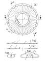
- Fig. 1 eine Draufsicht auf eine erfindungsgemäße Filterscheibe,
- Fig. 2 einen Schnitt nach der Linie 11-11 der Fig. 1,
- Fig. 3 einen Schnitt nach der Linie 111-111 der Fig. 1,
- Fig. 4 einen Halbschnitt in vergrößertem Maßstab durch mehrere Filterscheiben nach der Linie IV-IV der Fig.1,
- Fig. 5 eine Draufsicht auf eine Filterscheibe in anderer Ausgestaltung mit dem Filtergehäuse,
- Fig. 6 in Prinzipdarstellung eine Draufsicht auf eine Filterscheibe anderer Bauart in stark verkleinertem Maßstab,
- Fig. 7 in Prinzipdarstellung eine Draufsicht auf einen Abgasfilter mit zwei Paketen von Filterscheiben in einem gemeinsamen Filtergehäuse.
- 1 is a plan view of a filter disc according to the invention,
- 2 shows a section along the line 11-11 of FIG. 1,
- 3 shows a section along the line 111-111 of FIG. 1,
- 4 shows a half section on an enlarged scale through several filter disks along the line IV-IV of FIG. 1,
- 5 is a plan view of a filter disk in another embodiment with the filter housing,
- 6 is a schematic representation of a top view of a filter disc of another type on a greatly reduced scale,
- Fig. 7 in principle a plan view of an exhaust gas filter with two packets of filter disks in a common filter housing.
Der erfindungsgemäße Filterkörper besteht aus einer Vielzahl von übereinander angeordneten einzelnen Filterscheiben 1, die z.B. durch Schweißen, einem Sintervorgang oder durch mechanische Verbindungsglieder miteinander zu einer Einheit verbunden sind. (siehe Fig. 4). Hierzu können z.B. die flach aufeinander liegenden Außen- und Innenränder 10 bzw. 11 der Filterscheiben dienen. Die Oberfläche jeder Filterscheibe 1 ist wellenartig mit aufeinander folgenden Rippen 2 und Sicken 3 versehen. Jede Filterscheibe 1 besitzt einen freien zentralen Innenraum 4, der als koaxiale Bohrung ausgebildet ist.The filter body according to the invention consists of a plurality of
Die in einer gewünschten Anzahl zusammengefügten, übereinander angeordneten Filterscheiben 1 sind in einem Filtergehäuse 5 angeordnet, das mit einem Zulaufkanal 6 versehen ist (siehe Fig. 5). Der Zulaufkanal 6 kann radial, schräg oder - wie in der Fig. 5 dargestellt - tangential in einen Zwischenraum 7 zwischen den äußeren Umfangswänden der Filterscheiben 1 und der Innenwand des Filtergehäuses 5 einmünden.The
Wie aus der Fig. 4 ersichtlich ist, werden durch die Abstandshalter darstellende Rippen 2 und Sikken 3 die übereinander liegenden Filterscheiben 1 derart auf Abstand voneinander gehalten, daß sich Eingangskanäle 8 und Ausgangskanäle 9 ergeben. Hierzu werden die übereinander liegenden Filterscheiben 1 jeweils spiegelbildlich aufeinander gesetzt. Die in den Zwischenraum 7 einströmenden Abgase durchströmen dann in Pfeilrichtung aufgrund der Porosität die zwischen den Eingangs-und Ausgangskanälen 8 bzw. 9 liegenden Filterwände, wobei die Rußkonversion bzw. Rußverbrennung stattfindet.As can be seen from FIG. 4, the
Dabei ist lediglich dafür zu sorgen, daß die Filterwände eine entsprechend große Porosität besitzen. Hierzu wird man die formgepreßten und gesinterten Filterplatten im allgemeinen aus grobkörnigen oder noch besser, späneartigen oder faserartigen Metallfäden oder einem Gemisch daraus herstellen. So können z.B. aus endlichen oder endlosen Metallspänen oder Metallfasern gebildete Fasermatten oder Fasergeflechte hierfür verwendet werden.It is only necessary to ensure that the filter walls have a correspondingly large porosity. For this purpose, the compression-molded and sintered filter plates will generally be produced from coarse-grained or, even better, chip-like or fibrous metal threads or a mixture thereof. For example, Fiber mats or fiber braids formed from finite or endless metal chips or metal fibers can be used for this.
Bei den dargestellten Ausführungsbeispielen, bei denen die Abgase radial von außen nach innen durch die Filterscheiben strömen, bildet der freie Innenraum 4 den Abgaskanal.In the exemplary embodiments shown, in which the exhaust gases flow radially from the outside inwards through the filter disks, the
Während die Rippen 2 und Sicken 3 nach dem Ausführungsbeispiel gemäß Fig. 1 in radialer Richtung angeordnet sind, sind sie bei dem Ausführungsbeispiel nach der Fig. 5 gegen die radiale Richtung leitschaufelartig gekrümmt, womit sich in Verbindung mit dem tangentialen Zulaufkanal ein sehr gutes Strömungsverhalten ergibt.While the
Bei den Ausführungsbeispielen nach den Fig. 1 und 5 sind die Filterscheiben 1 diskusartig in kreisrunder Form ausgeführt.In the exemplary embodiments according to FIGS. 1 and 5, the
Gemäß verkleinerter Darstellung in der Fig. 6 ist jedoch auch eine Ovalform möglich, wobei die so geformten Filterscheiben 1 in einem ebenfalls entsprechend geformten Filtergehäuse angeordnet sind.According to the reduced representation in FIG. 6, however, an oval shape is also possible, the
In der Fig. 7 ist eine Ausführungsform dargestellt, wobei in einem Filtergehäuse 5' nebeneinander zwei Pakete von Filterscheiben 1' mit jeweils einem Abgaskanal 4' angeordnet sind. Wie ersichtlich, sind dabei die Filterscheiben als unregelmäßiges Viereck bzw. nierenförmig mit entsprechend stark abgerundeten Kanten ausgebildet.7 shows an embodiment, wherein two packets of filter disks 1 ', each with an exhaust gas duct 4', are arranged next to one another in a filter housing 5 '. As can be seen, the filter disks are designed as an irregular square or kidney-shaped with correspondingly rounded edges.
Selbstverständlich sind im Rahmen der Erfindung auch noch beliebig andere Formen von Filterscheiben 1 möglich.Of course, other forms of
Im Bedarfsfalle können die den Ausgangskanälen 9 zugewandten Filterwände der Filterscheiben 1 mit einem katalytisch wirkenden Werkstoff beschichtet werden. Verwendet man hierzu z.B. Platin, Vanadium, Rhodium o.dgl., so können nach einer Abscheidung bzw. Rußumwandlung in den Filterwänden problemlos auch noch Kohlenmonoxyd, Kohlenwasserstoffe und Stickstoffe abgeschieden werden.If necessary, the filter walls of the
Statt einer Beschichtung der Filterwände können (nicht dargestellt) zwischen an die aneinander stoßenden Rippen 2 und Sicken 3 von benachbart zueinander liegenden Filterscheiben auch Katalysatorplatten eingelegt werden, an deren Oberlfächen die Abgase auf ihrem Weg zum Innenraum 4 entlang strömen.Instead of coating the filter walls (not shown), catalyst plates can also be inserted between the abutting
Claims (12)
dadurch gekennzeichnet, daß die Filterplatten als übereinander liegende, in einem Filtergehäuse (5) angeordnete und einen freien zentralen Innenraum (4) aufweisende Filterscheiben (1) ausgebildet sind, die von außen nach innen oder von innen nach außen von den Abgasen durchströmt sind.1. Filter for separating contaminants from exhaust gases, in particular from the exhaust gases of an internal combustion engine, with a filter body which consists of a large number of compression-molded, high-temperature-resistant and sintered filter plates made of metal powder, metal chips, metal fibers or a mixture thereof, which are arranged one above the other or one behind the other and spaced apart from one another by spacers form a plurality of flow channels between them, the flow channels for forming input and output channels being open on one side and closed on the other side, and wherein the walls lying between the input and output channels Filter plate represent filter surfaces,
characterized in that the filter plates are designed as stacked filter disks (1) which are arranged in a filter housing (5) and have a free central interior (4) and through which the exhaust gases flow from outside to inside or from inside to outside.
dadurch gekennzeichnet, daß in den Zwischenraum (7) zwischen dem Filtergehäuse (5) und den Umfangswänden der Filterscheiben (1) wenigstens ein Zulaufkanal (6) mündet, und daß der zentrale Innenraum den Abgaskanal (4,4') darstellt.2. Filter according to claim 1,
characterized in that at least one inlet channel (6) opens into the intermediate space (7) between the filter housing (5) and the peripheral walls of the filter disks (1), and in that the central interior represents the exhaust gas channel (4,4 ').
dadurch gekennzeichnet, daß die Abstandshalter durch in die Filterscheiben (1) eingeformte Rippen (2), Sicken (3) o.dgl. gebildet sind.3. Filter according to claim 1 or 2,
characterized in that the spacers are formed by ribs (2), beads (3) or the like formed in the filter disks (1). are formed.
dadurch gekennzeichnet, daß die Filterscheiben (1), wellenartig ausgebildet sind und die Wellenberge und Wellentäler die Abstandshalter der übereinander liegenden Filterscheiben bilden.4. Filter according to claim 3,
characterized in that the filter disks (1) are wave-shaped and the wave crests and wave troughs form the spacers of the filter disks lying one above the other.
dadurch gekennzeichnet, daß die Abstandshalter (2,3) leitschaufelartig in radialer Richtung gekrümmt sind und daß der Zulaufkanal (6) gegen die radiale Richtung geneigt in das Filtergehäuse (5) mündet.5. Filter according to one of claims 1 to 4,
characterized in that the spacers (2, 3) are curved in the radial direction in the manner of a guide vane, and in that the inlet channel (6) opens into the filter housing (5) at an inclination to the radial direction.
dadurch gekennzeichnet, daß der Zulaufkanal (6) tangential in das Filtergehäuse (5) mündet.6. Filter according to claim 5,
characterized in that the inlet channel (6) opens tangentially into the filter housing (5).
dadurch gekennzeichnet, daß die Filterscheiben (1) diskusartig ausgebildet sind.7. Filter according to claim 6,
characterized in that the filter discs (1) are disc-like.
dadurch gekennzeichnet, daß die Filterscheiben (1) wenigstens annähernd eine Oval-oder Ellipsenform besitzen.8. Filter according to one of claims 1 to 5,
characterized in that the filter disks (1) have at least approximately an oval or elliptical shape.
dadurch gekennzeichnet, daß zwei oder mehrere Pakete von Filterscheiben (1') nebeneinander in einem gemeinsamen Filtergehäuse (5') angeordnet sind.9. Filter according to one of claims 1 to 8,
characterized in that two or more packages of filter disks (1 ') are arranged side by side in a common filter housing (5').
dadurch gekennzeichnet, daß die formgepreßten Filterscheiben (1) gemeinsam in einem Sintervorgang zu einem einheitlichen Filterkörper zusammengesintert oder durch Schweißen zu einem einheitlichen Filterkörper miteinander verbunden sind.10. Filter according to one of claims 1 to 9,
characterized in that the compression-molded filter disks (1) are sintered together in a sintering process to form a uniform filter body or are connected to one another by welding to form a uniform filter body.
dadurch gekennzeichnet, daß die formgepreßten und gesinterten Filterscheiben (1) durch mechanische Verbindungsglieder zu einem einheitlichen Filterkörper miteinander verbunden sind.11. Filter according to one of claims 1 to 9,
characterized in that the compression-molded and sintered filter disks (1) are connected to one another by mechanical connecting links to form a uniform filter body.
Applications Claiming Priority (2)
| Application Number | Priority Date | Filing Date | Title |
|---|---|---|---|
| DE4029749A DE4029749A1 (en) | 1990-09-20 | 1990-09-20 | FILTER |
| DE4029749 | 1990-09-20 |
Publications (2)
| Publication Number | Publication Date |
|---|---|
| EP0482307A1 true EP0482307A1 (en) | 1992-04-29 |
| EP0482307B1 EP0482307B1 (en) | 1995-03-22 |
Family
ID=6414589
Family Applications (1)
| Application Number | Title | Priority Date | Filing Date |
|---|---|---|---|
| EP91113548A Expired - Lifetime EP0482307B1 (en) | 1990-09-20 | 1991-08-13 | Filter |
Country Status (8)
| Country | Link |
|---|---|
| US (1) | US5215724A (en) |
| EP (1) | EP0482307B1 (en) |
| JP (1) | JPH04260411A (en) |
| KR (1) | KR920006019A (en) |
| AT (1) | ATE120099T1 (en) |
| CA (1) | CA2050118A1 (en) |
| DE (2) | DE4029749A1 (en) |
| ES (1) | ES2073625T3 (en) |
Families Citing this family (27)
| Publication number | Priority date | Publication date | Assignee | Title |
|---|---|---|---|---|
| DE4201111C2 (en) * | 1992-01-17 | 1994-03-10 | Daimler Benz Ag | Exhaust filter, in particular soot particle filter |
| DE4234930A1 (en) * | 1992-10-16 | 1994-04-21 | Schwaebische Huettenwerke Gmbh | Filters for separating contaminants from exhaust gases |
| US5359946A (en) * | 1993-06-08 | 1994-11-01 | Kabushiki Kaisha Daito | Combustion gas purifying method, acid gas remover including calcium compound to remove acid gases, and incinerator equipped with such acid gas remover |
| US5902558A (en) * | 1994-09-26 | 1999-05-11 | Emitec Gesellschaft Fuer Emissionstechnologie Mbh | Diskwise-constructed honeycomb body, in particular catalyst carrier body and apparatus for catalytic conversion of exhaust gases |
| US5494506A (en) * | 1995-01-17 | 1996-02-27 | Ucar Carbon Technology Corporation | Gas filtering device for air bag gas generator |
| US5609837A (en) * | 1995-08-16 | 1997-03-11 | Cerny; David E. | Disinfection apparatus |
| JP3504801B2 (en) * | 1996-03-26 | 2004-03-08 | 東北リコー株式会社 | Master and plate cylinder and ink holding member of stencil printing machine |
| EP1015099A4 (en) | 1997-01-10 | 2003-01-22 | Ellipsis Corp | Micro and ultrafilters with controlled pore sizes and pore size distribution and method for making |
| GB9801564D0 (en) * | 1998-01-27 | 1998-03-25 | Ici Plc | Catalyst |
| US6168651B1 (en) * | 1998-10-08 | 2001-01-02 | Donaldson Company, Inc. | Filter assembly with shaped adsorbent article; and devices and methods of use |
| US20030038088A1 (en) * | 2000-02-23 | 2003-02-27 | Geert Denys | Filter element |
| WO2001062365A1 (en) * | 2000-02-23 | 2001-08-30 | N.V. Bekaert S.A. | Pleated filter element |
| FR2812221B1 (en) * | 2000-07-28 | 2003-04-04 | Butachimie | NEW CATALYTIC DEVICE FOR IMPLEMENTING A REACTION IN A HIGH-TEMPERATURE GASEOUS MEDIUM |
| DE10117086A1 (en) * | 2001-04-06 | 2002-10-17 | Emitec Emissionstechnologie | Process for producing a one-piece, structured sheet metal foil with a hole, sheet metal foil and honeycomb body |
| EP1251248A1 (en) * | 2001-04-18 | 2002-10-23 | OMG AG & Co. KG | Method and arrangement to remove soot particles from the exhaust gas of a diesel engine |
| DE10331347A1 (en) * | 2003-07-11 | 2005-02-03 | Purem Abgassysteme Gmbh & Co. Kg | Filter bag for a particle filter |
| DE102004037706A1 (en) * | 2004-08-04 | 2006-03-16 | Purem Abgassysteme Gmbh & Co. Kg | Filter plate for a particle filter |
| DE102004038331A1 (en) * | 2004-08-06 | 2006-03-16 | Emitec Gesellschaft Für Emissionstechnologie Mbh | Metallic fibers, their production and applications |
| DE102004054158A1 (en) | 2004-11-10 | 2006-05-11 | Purem Abgassysteme Gmbh & Co. Kg | Filter plate for a particle filter |
| KR100653248B1 (en) * | 2005-06-23 | 2006-12-01 | 삼성전기주식회사 | Light quaint adjusting apparatus |
| RU2397006C2 (en) * | 2005-07-01 | 2010-08-20 | Хеганес Аб | Stainless steel for use in filters |
| JP2010535696A (en) * | 2007-08-03 | 2010-11-25 | エアシブ・インコーポレーテッド | Porous body and method |
| JP4564520B2 (en) * | 2007-08-31 | 2010-10-20 | 株式会社東芝 | Semiconductor memory device and control method thereof |
| US8277743B1 (en) | 2009-04-08 | 2012-10-02 | Errcive, Inc. | Substrate fabrication |
| US8359829B1 (en) | 2009-06-25 | 2013-01-29 | Ramberg Charles E | Powertrain controls |
| KR101065835B1 (en) * | 2009-12-28 | 2011-09-19 | 주식회사 리홈 | Impeller disk assembly for evaporite humidifier |
| US9833932B1 (en) | 2010-06-30 | 2017-12-05 | Charles E. Ramberg | Layered structures |
Citations (5)
| Publication number | Priority date | Publication date | Assignee | Title |
|---|---|---|---|---|
| WO1981002686A1 (en) * | 1980-03-19 | 1981-10-01 | J Bailey | Engine exhaust particulate filter |
| DE3504694A1 (en) * | 1985-02-12 | 1986-08-14 | Knecht Filterwerke Gmbh, 7000 Stuttgart | Exhaust filter for internal combustion engines |
| DE3712872A1 (en) * | 1986-04-18 | 1987-10-22 | Sartorius Gmbh | Filter element for fluids and process for producing a filter element |
| EP0331885A1 (en) * | 1988-03-10 | 1989-09-13 | Schwäbische Hüttenwerke Gesellschaft mit beschränkter Haftung | Exhaust gas filter |
| DE3815148A1 (en) * | 1988-05-04 | 1989-11-16 | Eberspaecher J | Arrangement for mounting an exhaust gas filter in a metal housing |
Family Cites Families (29)
| Publication number | Priority date | Publication date | Assignee | Title |
|---|---|---|---|---|
| US2267918A (en) * | 1940-03-27 | 1941-12-30 | Gen Motors Corp | Porous article and method of making same |
| US3161478A (en) * | 1959-05-29 | 1964-12-15 | Horst Corp Of America V D | Heat resistant porous structure |
| US3087233A (en) * | 1960-11-16 | 1963-04-30 | Fram Corp | Pervious metal fiber material and method of making the same |
| US3306353A (en) * | 1964-12-23 | 1967-02-28 | Olin Mathieson | Heat exchanger with sintered metal matrix around tubes |
| US3904551A (en) * | 1973-12-19 | 1975-09-09 | Grace W R & Co | Process for preparing an auto exhaust catalytic converter |
| US4064914A (en) * | 1974-05-08 | 1977-12-27 | Union Carbide Corporation | Porous metallic layer and formation |
| US4062807A (en) * | 1975-06-17 | 1977-12-13 | Tokyo Shibaura Electric Co., Ltd. | Nitrogen oxide reducing catalyst |
| US4183896A (en) * | 1976-06-16 | 1980-01-15 | Gordon Donald C | Anti-pollution device for exhaust gases |
| JPS54128842A (en) * | 1978-03-29 | 1979-10-05 | Bridgestone Corp | Thermal collector |
| JPS54152241A (en) * | 1978-04-20 | 1979-11-30 | Mtp Kasei Kk | Solar heat collecting body |
| US4301012A (en) * | 1979-04-25 | 1981-11-17 | Purolator Technologies, Inc. | Welded stainless steel mesh cleanable filter |
| JPS577216A (en) * | 1980-06-16 | 1982-01-14 | Ngk Insulators Ltd | Ceramic honeycomb filter and preparation thereof |
| US4329162A (en) * | 1980-07-03 | 1982-05-11 | Corning Glass Works | Diesel particulate trap |
| AU540009B2 (en) * | 1982-02-16 | 1984-10-25 | Matsushita Electric Industrial Co., Ltd. | Exhaust gas filter |
| DE3232729A1 (en) * | 1982-09-03 | 1984-03-08 | Degussa Ag, 6000 Frankfurt | METHOD FOR REDUCING THE IGNITION TEMPERATURE OF DIESEL CARBON FILTERED OUT OF THE EXHAUST GAS FROM DIESEL ENGINES |
| DE3570414D1 (en) * | 1984-07-09 | 1989-06-29 | Takeda Chemical Industries Ltd | Powder-air filter and separator for use in a powder filling apparatus |
| JPS61287451A (en) * | 1985-06-13 | 1986-12-17 | Nippon Denso Co Ltd | Catalytic carrier for purifying exhaust gas |
| JPH062204B2 (en) * | 1985-06-24 | 1994-01-12 | 日本電装株式会社 | Ceramic structure |
| DE3527111A1 (en) * | 1985-07-29 | 1987-01-29 | Interatom | METAL, WINDED EXHAUST GAS CATALYST SUPPORT BODY WITH A GEOMETRICALLY COMPLEX FORM OF THE CROSS-SECTION, AND METHOD, DEVICE AND ROLLING FOR ITS PRODUCTION |
| DE3533924A1 (en) * | 1985-09-24 | 1987-06-19 | Schumacher Sche Fab Verwalt | FILTER BODY AND METHOD FOR THE PRODUCTION THEREOF |
| US4725411A (en) * | 1985-11-12 | 1988-02-16 | W. R. Grace & Co. | Device for physical and/or chemical treatment of fluids |
| JPH0657288B2 (en) * | 1986-03-25 | 1994-08-03 | 旭硝子株式会社 | Patty Yule Trap |
| DE3614347A1 (en) * | 1986-04-28 | 1987-10-29 | Didier Werke Ag | CATALYST BLOCK |
| US4687579A (en) * | 1986-05-02 | 1987-08-18 | The United States Of America As Represented By The United States Department Of Energy | Sintered composite medium and filter |
| US4758272A (en) * | 1987-05-27 | 1988-07-19 | Corning Glass Works | Porous metal bodies |
| DE3828348A1 (en) * | 1988-08-20 | 1990-02-22 | Schwaebische Huettenwerke Gmbh | DEVICE FOR HEAT TRANSFER |
| DE3828347A1 (en) * | 1988-08-20 | 1990-03-01 | Schwaebische Huettenwerke Gmbh | EXHAUST GAS FILTER FOR HEATING OR COMBUSTION PLANTS |
| IT1232749B (en) * | 1989-04-12 | 1992-03-05 | I R T I Istituto Di Ricerca E | EXHAUST GAS PURIFIER WITH CATALYTIC ACTIVITY AND SILENCER FOR INTERNAL COMBUSTION ENGINES |
| DE3937809A1 (en) * | 1989-11-14 | 1991-05-16 | Schwaebische Huettenwerke Gmbh | FILTER FOR SEPARATING IMPURITIES |
-
1990
- 1990-09-20 DE DE4029749A patent/DE4029749A1/en not_active Withdrawn
-
1991
- 1991-08-13 ES ES91113548T patent/ES2073625T3/en not_active Expired - Lifetime
- 1991-08-13 DE DE59104991T patent/DE59104991D1/en not_active Expired - Fee Related
- 1991-08-13 EP EP91113548A patent/EP0482307B1/en not_active Expired - Lifetime
- 1991-08-13 AT AT91113548T patent/ATE120099T1/en active
- 1991-08-28 CA CA002050118A patent/CA2050118A1/en not_active Abandoned
- 1991-09-04 KR KR1019910015442A patent/KR920006019A/en not_active Application Discontinuation
- 1991-09-05 US US07/755,168 patent/US5215724A/en not_active Expired - Fee Related
- 1991-09-19 JP JP3268490A patent/JPH04260411A/en active Pending
Patent Citations (5)
| Publication number | Priority date | Publication date | Assignee | Title |
|---|---|---|---|---|
| WO1981002686A1 (en) * | 1980-03-19 | 1981-10-01 | J Bailey | Engine exhaust particulate filter |
| DE3504694A1 (en) * | 1985-02-12 | 1986-08-14 | Knecht Filterwerke Gmbh, 7000 Stuttgart | Exhaust filter for internal combustion engines |
| DE3712872A1 (en) * | 1986-04-18 | 1987-10-22 | Sartorius Gmbh | Filter element for fluids and process for producing a filter element |
| EP0331885A1 (en) * | 1988-03-10 | 1989-09-13 | Schwäbische Hüttenwerke Gesellschaft mit beschränkter Haftung | Exhaust gas filter |
| DE3815148A1 (en) * | 1988-05-04 | 1989-11-16 | Eberspaecher J | Arrangement for mounting an exhaust gas filter in a metal housing |
Also Published As
| Publication number | Publication date |
|---|---|
| ATE120099T1 (en) | 1995-04-15 |
| JPH04260411A (en) | 1992-09-16 |
| CA2050118A1 (en) | 1992-03-21 |
| EP0482307B1 (en) | 1995-03-22 |
| ES2073625T3 (en) | 1995-08-16 |
| US5215724A (en) | 1993-06-01 |
| DE59104991D1 (en) | 1995-04-27 |
| DE4029749A1 (en) | 1992-03-26 |
| KR920006019A (en) | 1992-04-27 |
Similar Documents
| Publication | Publication Date | Title |
|---|---|---|
| EP0482307B1 (en) | Filter | |
| EP0428037B1 (en) | Filter for eliminating pollutants | |
| EP0379032B1 (en) | Waste gas filter | |
| EP0467147B1 (en) | Filter or catalyst body | |
| EP0593004B1 (en) | Filter for removing pollutants from offgas | |
| DE19704147A1 (en) | Heat-resistant and regenerable filter body with flow paths | |
| DE3818281A1 (en) | EXHAUST FILTER | |
| EP0470365B1 (en) | Filter | |
| EP0411421B1 (en) | Process for the production of a filter and filter produced thereby | |
| DE60313151T2 (en) | TREATMENT OF EXHAUST GASES FROM A COMBUSTION ENGINE | |
| EP1174599B1 (en) | Filter system for an exhaust gas cleaning device | |
| EP1559882B1 (en) | Exhaust purification device and process for manufacturing an exhaust purification device | |
| DE10212236A1 (en) | Automotive engine exhaust manifold with internal catalytic converter | |
| EP2299076B1 (en) | Particulate filter for an internal combustion engine | |
| EP2194251B1 (en) | Self-supporting holder for catalytic converter support | |
| DE102018216841B4 (en) | Particle filter | |
| DE3626729C2 (en) | ||
| DE4205357C2 (en) | Engine exhaust filter | |
| EP1431528B1 (en) | Exhaust purification device | |
| EP1262640B1 (en) | Exhaust line of an internal engine, especially diesel engine from utility vehicules such as trucks or buses, with an integrated device for treating an exhaust gas an attenuate noise | |
| DE19933442A1 (en) | Particulate filter e.g. soot filter used in exhaust gas in an internal combustion engine has filter medium and catalyst forming rope-like shape and wound into one of the cylindrical filters | |
| DE1907027B2 (en) | Device for treating a compound in the gas phase on a solid | |
| EP0469277A1 (en) | Filter device | |
| DE10301138A1 (en) | Exhaust gas treatment unit, useful for reducing automobile pollutant emissions, has connector, such that gas passes through forward flow zone of honeycomb structure and then through backflow zone | |
| DE102018219724A1 (en) | Particle filter for an exhaust system and method for producing a particle filter |
Legal Events
| Date | Code | Title | Description |
|---|---|---|---|
| PUAI | Public reference made under article 153(3) epc to a published international application that has entered the european phase |
Free format text: ORIGINAL CODE: 0009012 |
|
| AK | Designated contracting states |
Kind code of ref document: A1 Designated state(s): AT BE DE ES FR GB IT NL SE |
|
| 17P | Request for examination filed |
Effective date: 19920422 |
|
| 17Q | First examination report despatched |
Effective date: 19930729 |
|
| GRAA | (expected) grant |
Free format text: ORIGINAL CODE: 0009210 |
|
| AK | Designated contracting states |
Kind code of ref document: B1 Designated state(s): AT BE DE ES FR GB IT NL SE |
|
| REF | Corresponds to: |
Ref document number: 120099 Country of ref document: AT Date of ref document: 19950415 Kind code of ref document: T |
|
| REF | Corresponds to: |
Ref document number: 59104991 Country of ref document: DE Date of ref document: 19950427 |
|
| ITF | It: translation for a ep patent filed |
Owner name: STUDIO CONS. BREVETTUALE S.R.L. |
|
| ET | Fr: translation filed | ||
| GBT | Gb: translation of ep patent filed (gb section 77(6)(a)/1977) |
Effective date: 19950616 |
|
| REG | Reference to a national code |
Ref country code: ES Ref legal event code: FG2A Ref document number: 2073625 Country of ref document: ES Kind code of ref document: T3 |
|
| PLBE | No opposition filed within time limit |
Free format text: ORIGINAL CODE: 0009261 |
|
| STAA | Information on the status of an ep patent application or granted ep patent |
Free format text: STATUS: NO OPPOSITION FILED WITHIN TIME LIMIT |
|
| 26N | No opposition filed | ||
| PGFP | Annual fee paid to national office [announced via postgrant information from national office to epo] |
Ref country code: GB Payment date: 19960809 Year of fee payment: 6 |
|
| PGFP | Annual fee paid to national office [announced via postgrant information from national office to epo] |
Ref country code: ES Payment date: 19960813 Year of fee payment: 6 |
|
| PGFP | Annual fee paid to national office [announced via postgrant information from national office to epo] |
Ref country code: AT Payment date: 19960814 Year of fee payment: 6 |
|
| PGFP | Annual fee paid to national office [announced via postgrant information from national office to epo] |
Ref country code: SE Payment date: 19960819 Year of fee payment: 6 |
|
| PGFP | Annual fee paid to national office [announced via postgrant information from national office to epo] |
Ref country code: DE Payment date: 19960822 Year of fee payment: 6 |
|
| PGFP | Annual fee paid to national office [announced via postgrant information from national office to epo] |
Ref country code: FR Payment date: 19960826 Year of fee payment: 6 |
|
| PGFP | Annual fee paid to national office [announced via postgrant information from national office to epo] |
Ref country code: NL Payment date: 19960828 Year of fee payment: 6 |
|
| PGFP | Annual fee paid to national office [announced via postgrant information from national office to epo] |
Ref country code: BE Payment date: 19960904 Year of fee payment: 6 |
|
| PG25 | Lapsed in a contracting state [announced via postgrant information from national office to epo] |
Ref country code: GB Free format text: LAPSE BECAUSE OF NON-PAYMENT OF DUE FEES Effective date: 19970813 Ref country code: AT Free format text: LAPSE BECAUSE OF NON-PAYMENT OF DUE FEES Effective date: 19970813 |
|
| PG25 | Lapsed in a contracting state [announced via postgrant information from national office to epo] |
Ref country code: SE Free format text: LAPSE BECAUSE OF NON-PAYMENT OF DUE FEES Effective date: 19970814 Ref country code: ES Free format text: LAPSE BECAUSE OF EXPIRATION OF PROTECTION Effective date: 19970814 |
|
| PG25 | Lapsed in a contracting state [announced via postgrant information from national office to epo] |
Ref country code: BE Free format text: LAPSE BECAUSE OF NON-PAYMENT OF DUE FEES Effective date: 19970831 |
|
| BERE | Be: lapsed |
Owner name: SCHWABISCHE HUTTENWERKE G.M.B.H. Effective date: 19970831 |
|
| PG25 | Lapsed in a contracting state [announced via postgrant information from national office to epo] |
Ref country code: NL Free format text: LAPSE BECAUSE OF NON-PAYMENT OF DUE FEES Effective date: 19980301 |
|
| GBPC | Gb: european patent ceased through non-payment of renewal fee |
Effective date: 19970813 |
|
| PG25 | Lapsed in a contracting state [announced via postgrant information from national office to epo] |
Ref country code: FR Free format text: LAPSE BECAUSE OF NON-PAYMENT OF DUE FEES Effective date: 19980430 |
|
| PG25 | Lapsed in a contracting state [announced via postgrant information from national office to epo] |
Ref country code: DE Free format text: LAPSE BECAUSE OF NON-PAYMENT OF DUE FEES Effective date: 19980501 |
|
| EUG | Se: european patent has lapsed |
Ref document number: 91113548.1 |
|
| NLV4 | Nl: lapsed or anulled due to non-payment of the annual fee |
Effective date: 19980301 |
|
| REG | Reference to a national code |
Ref country code: FR Ref legal event code: ST |
|
| REG | Reference to a national code |
Ref country code: ES Ref legal event code: FD2A Effective date: 20010201 |
|
| PG25 | Lapsed in a contracting state [announced via postgrant information from national office to epo] |
Ref country code: IT Free format text: LAPSE BECAUSE OF NON-PAYMENT OF DUE FEES;WARNING: LAPSES OF ITALIAN PATENTS WITH EFFECTIVE DATE BEFORE 2007 MAY HAVE OCCURRED AT ANY TIME BEFORE 2007. THE CORRECT EFFECTIVE DATE MAY BE DIFFERENT FROM THE ONE RECORDED. Effective date: 20050813 |