EP0482015B1 - Dispositif de securite pour les occupants d'un vehicule - Google Patents
Dispositif de securite pour les occupants d'un vehicule Download PDFInfo
- Publication number
- EP0482015B1 EP0482015B1 EP90909331A EP90909331A EP0482015B1 EP 0482015 B1 EP0482015 B1 EP 0482015B1 EP 90909331 A EP90909331 A EP 90909331A EP 90909331 A EP90909331 A EP 90909331A EP 0482015 B1 EP0482015 B1 EP 0482015B1
- Authority
- EP
- European Patent Office
- Prior art keywords
- safety system
- circuit
- blocking
- time
- computing unit
- Prior art date
- Legal status (The legal status is an assumption and is not a legal conclusion. Google has not performed a legal analysis and makes no representation as to the accuracy of the status listed.)
- Expired - Lifetime
Links
Images
Classifications
-
- B—PERFORMING OPERATIONS; TRANSPORTING
- B60—VEHICLES IN GENERAL
- B60R—VEHICLES, VEHICLE FITTINGS, OR VEHICLE PARTS, NOT OTHERWISE PROVIDED FOR
- B60R21/00—Arrangements or fittings on vehicles for protecting or preventing injuries to occupants or pedestrians in case of accidents or other traffic risks
- B60R21/01—Electrical circuits for triggering passive safety arrangements, e.g. airbags, safety belt tighteners, in case of vehicle accidents or impending vehicle accidents
Definitions
- the invention relates to an occupant safety system for vehicles, in particular a restraint system, such as an airbag, belt tensioner, etc., according to the preamble of the main claim.
- a restraint system such as an airbag, belt tensioner, etc.
- Vehicles in particular passenger cars, are increasingly being equipped with occupant safety systems which offer occupants protection against injuries in the event of a collision or the like.
- the airbag system known from the magazine ATZ 84 (1982) 2, pp. 77-83 should be mentioned. With such systems, false triggering must be avoided, since they pose great dangers. Unintentional airbag deployment not only takes the driver of the passenger vehicle away from view for at least a certain period of time, but also - among other things due to the accompanying noise - scares the driver, so that their responsiveness is brief, but at least limited.
- an airbag cannot be reused after being deployed. Reinstalling the system creates considerable costs.
- Two essential criteria that can lead to false tripping in the electronic restraint systems mentioned are undefined hardware states during the switching on and off, for. B. a trigger sensor as well as malfunctions or faults in a computing unit that controls an ignition output stage of the safety system.
- the trigger sensor When the trigger sensor is switched on and off, the associated supply voltage runs through the entire voltage range. This can cause conditions in which, for. B. integrated switch circuit of the trigger sensor have no defined function, so that a false trigger can occur.
- the above-mentioned malfunctions or malfunctions of the computing unit also lead to undefined states, so that an unwanted activation of the ignition output stage of the safety system can occur.
- an ignition device for protective devices in vehicles which comprises a pyroelectric ignition element, to which an electronic lock 4 and a controlled switch releasing the energization of the detonator are assigned. Only after transmission of an unlocking signal, exposure to an ignition signal leads to energization of the ignition element, as a result of which an unwanted ignition triggering, e.g. B. is prevented by accidental application of an external voltage to the connections of the ignition device. The transmission of the unlocking signal leads without delay to an actuation of the controlled switch 3 and thus to a release of the ignition device.
- the occupant safety system according to the invention has the advantage that locking is activated by a blocking circuit controlled by the computing unit the ignition stage and thereby avoiding false triggering.
- the blocking circuit only unlocks the ignition output stage after a predefinable lock release time, the lock release time being less than a response time of the trigger sensor.
- the electronic trigger sensor detects certain driving state variables and, if predefined criteria are met, triggers the occupant safety system.
- the trigger sensor can, for example, detect the vehicle acceleration and process it in one or more digital or analog computing circuits, in particular carry out an integration. If a certain size is exceeded, it is triggered. From this it can be seen that, due to the integration process, the system is not triggered immediately, but only after the specified response time.
- the locking release time For a safe protective function, that is to say an activation of the occupant safety system before the occurrence of acceleration values which can lead to injury to the occupants, the locking release time must not exceed a certain period of time. In particular, it is necessary that the trigger pulse coming from the trigger sensor is fed to the unlocked ignition output stage so that system activation can take place.
- the locking release time according to the invention must therefore have already expired by this time. However, this makes it possible to examine the present state of the security system for its correct operating state. In particular, it can be checked whether the electronic components of the trigger sensor and the computing unit are each in the correct state, so that in each case the desired, defined function is available.
- the time-delayed release enables a "saving intervention" for a certain period of time.
- a further, undisturbed computing unit preferably a microcomputer
- the locking release time is preferably greater than an interval time of a monitoring circuit.
- This can be formed in particular by a further computing unit and / or a window watchdog circuit or the like.
- a window watchdog circuit is provided that the time interval for monitoring is smaller than the lock release time, the window watchdog circuit locked the ignition power stage directly and keeps locked for a blocking time.
- an undervoltage detection circuit which operates at a fraction of the nominal supply voltage of the safety system and locks the ignition output stage until the supply voltage has exceeded a threshold which ensures the functionality of the entire circuit arrangement. Faults in the voltage supply, which can lead to undefined states of the computing unit, do not lead to an undesired triggering of the security system due to the blocking circuit according to the invention. Due to the undervoltage detection circuit, in particular when the system is switched on and off, it is prevented that undefined states occurring in the integrated circuits due to the rise or fall of the supply voltage can trigger the safety system. This takes place through the aforementioned ignition output stage locking, which is only released when the supply voltage is greater than the predefinable threshold.
- the undervoltage detection circuit maintains the locking of the ignition output stage until a predefinable blocking time has elapsed from the time the threshold was exceeded. This blocking time after restoration of a sufficient voltage potential therefore ensures that a period is available in which the operating state can be checked. If undefined conditions or functions are determined, these cannot lead to a false triggering of the safety system due to the locking of the ignition output stage.
- the computing unit takes over the ignition output stage locking effected by the blocking circuit.
- the undervoltage detection circuit ensures that the ignition output stage is locked during an undervoltage phase of the supply voltage. This also applies due to the blocking period for a certain period of time after the restoration of sufficient voltage potential. Subsequently, the locking of the ignition output stage is then taken over by the computing unit in connection with the blocking circuit according to the invention, so that a locking of the ignition output stage is always guaranteed and thus an incorrect triggering is effectively countered. Only when the safety system is triggered intentionally is the locking of the ignition output stage released in compliance with the time condition according to the invention, so that there is a high level of security with regard to incorrect triggering up to this point in time.
- the computing unit has a blocking connection which drives the blocking circuit.
- the computing unit also has a reset input, and when a reset pulse is applied to this reset input, it puts the blocking connection into its locked state, so that it is not possible for the ignition output stages to respond.
- the blocking connection is connected to an interrupt connection of the computing unit. If the blocking connection assumes a state that leads to the unlocking of the ignition output stage, the interrupt connection can be activated a check routine is started immediately, which reveals whether the release of the ignition output stage lock has been justified. For example, a specific test program can be started via the interrupt connection or a specific program position can be jumped to, whereby the test mentioned is initiated.
- the output of the undervoltage detection circuit is connected to the reset input of the computing unit. This ensures that there are no false triggers when there are faults due to an undervoltage condition.
- a window watchdog circuit that is triggered by the computing unit at certain time intervals is advantageous. This is connected to the reset input of the computing unit. If the arithmetic unit controls the window watchdog circuit within the time window sequence, the emission of a reset pulse is suppressed. If the trigger pulses are omitted, for example due to a "hang" in the program sequence, or if trigger pulses occur that lie outside the time window, the window watchdog circuit issues a reset pulse to the reset input of the computing unit, which results in a reset. As a result, the ignition output stage is placed in its locked state. In addition, a direct ignition power stage lock is provided to cover possible defects in the reset branch.
- the blocking circuit preferably has a comparator, the first input of which is connected to a reference voltage and the other, second input of which is connected to the blocking connection via a connection point.
- a time constant circuit fed by the supply voltage is also connected to the connection point. This consists of an R / C element, the resistance of which is connected between the one pole of the supply voltage and the connection point and the capacitor of which is connected between the other pole of the supply voltage and the connection point.
- the output of the comparator is connected to a locking circuit that controls the output stage.
- the capacitor C of the R / C element is charged via the resistor R from the supply voltage.
- the blocking connection of the computing unit is at a potential (preferably ground) at which the capacitor discharges at least to the extent that its voltage is lower than the reference voltage is.
- the comparator switches to a state which locks the ignition output stage.
- the output of the comparator can only switch to a state which releases the locking of the ignition output stage when the capacitor connected to its second input is charged to a potential greater than that via the resistance of the R / C element from the supply voltage is reference voltage at its first input.
- the switchover time can thus be determined via the time constant of the R / C element. This changeover time corresponds to the locking release time according to the invention, since when the comparator is switched over, the voltage level at its output brings about an unlocking of the ignition output stage.
- the comparator is connected to the ignition output stage via a locking circuit.
- the locking circuit preferably has a controllable blocking switching means which can be controlled both by a switching element controlled by the size of the supply voltage and by the comparator.
- the switching element is switched through even at a low voltage, which only makes up a fraction of the nominal supply voltage, as a result of which the controllable blocking switching means of the locking circuit is put into a state that blocks the ignition output stage. This means that there is a blocking preventing false triggering before the supply voltage has risen to a value which enables the other components of the safety system to function.
- the undervoltage detection circuit detects a sufficiently high supply voltage, a power-on reset is given to the reset input of the arithmetic unit after the blocking time has elapsed, and at the same time the switching element is reversed in such a way that the switching state of the blocking switching means which would cause the ignition output stage to lock would now be canceled , provided that a corresponding signal is also provided at the output of the comparator.
- the latter is not the case, since the reset pulse at the reset input of the computing unit leads to such a state at the blocking connection of the computing unit that the voltage of the capacitor of the R / C element is less than the reference voltage.
- the comparator assumes a state at its output which controls the blocking switching means in such a way that the ignition output stage is locked.
- this locking is only released in the event of an intentional triggering, that is to say a triggering of the trigger sensor after the locking release time according to the invention has expired, a check for the correct state of the system components involved being carried out according to the invention during the locking release time.
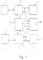
- the occupant safety system for vehicles has a trigger sensor 1, which is connected to a computing unit 2.
- the computing unit 2 is connected to an undervoltage detection circuit 3.
- a blocking circuit 21 is also provided, which is connected to an ignition output stage 5.
- the ignition output stage 5 is used to trigger the occupant safety system, which is designed, for example, as an airbag.
- the ignition output stage 5 accordingly controls a squib of a propellant charge of the airbag.
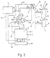
- FIG. 2 shows that the undervoltage supply circuit 3 has an output 6 which drives a switching element 7.
- the switching element 7 is designed as a transistor T1.
- the base of the transistor T1 is connected via a resistor R1 to the positive pole of a supply voltage U v .
- the emitter of the transistor T1 is at the other pole of the supply voltage U v , which is formed by ground 8.
- connection point 9 is connected to the collector of the transistor T1 via a resistor R2. Furthermore, there is another resistor between the connection point 9 and the positive pole of the supply voltage U v R3 switched.
- the connection point 9 is also connected to the control connection of a controllable blocking switching means 10, which is designed as a transistor T2.
- the control connection is formed by the base of the transistor T2.
- the emitter of the transistor T2 is connected to the positive pole of the supply voltage U v , while the collector thereof leads to a distribution line 11.
- FIG. 2 shows two ignition output stages 5 which have output stage transistors T E.
- the switching paths of the output stage transistors 5 each have a connection to ground 8 and the other connection 12 to ignition pills (not shown) of the airbag system.
- the control connections 13 are connected to control outputs a and b of the computing unit 2. Furthermore, the control terminals 13 are connected to the respective collectors of the transistors T3 and T4, whose emitters are connected to ground 8.
- the respective bases of the transistors T3 and T4 are connected to the distribution line 11 via resistors R4 and R5.
- the transistors T2, T3 and T4 belong - with their wiring elements - to a latch circuit 14.
- An output 15 of the undervoltage detection circuit 3 leads to a reset input 16 of the computing unit 2. This has an output 17 which leads to a window watchdog circuit 18.
- the reset input 16 of the computing unit 2 is connected to an output 19 of the window watchdog circuit 18.
- Another output 30 of the window watchdog circuit 18 leads to the base of the transistor T1.
- the computing unit 2 also has a blocking connection 20, to which a blocking circuit 21 is connected.
- This has a comparator K, the first input 22 of which is connected to a reference voltage U Ref and the other, second input 23 of which leads to a time constant circuit 24.
- the time constant circuit 24 is formed by an R / C element 25, which has a resistor R and a capacitor C.
- the resistor R is connected with its one connection to the positive pole of the supply voltage U v um with its other connection to a connection point 26 at which the one connection of the capacitor C is also located.
- the other connection of the capacitor C is connected to ground 8.
- a diode D is also connected to the connection point 26 with its anode.
- the cathode of the diode D leads to the blocking connection 20.
- the blocking connection 20 can also be connected to an interrupt connection 27. This is indicated by dashed lines in FIG. 2.
- the output 28 of the comparator K is connected to the connection point 9.
- the occupant safety system works as follows: When the supply voltage U v is switched on, the transistor T 1 is already switched through at a very low voltage level (U v ⁇ 1V). The transistor T1 controls the base of the transistor T2 via its collector and the resistor R2 in such a way that it also assumes its conductive state. This leads to a control of the transistors T3 and T4 etc. (there may be further transistors connected to the connecting line 11, control the corresponding ignition output stages 5). By driving the transistors T3 and T4 are put in their conductive states, so that the control terminals 13 of the output stage transistors T E assume ground potential.
- undervoltage detection circuit 3 detects an undervoltage, there is a static reset state. If there is a sufficiently high supply voltage U v , a power-on reset pulse is started during a blocking time after a predefinable threshold has been exceeded. After the blocking time t s has elapsed, the permanent reset is removed, which has resulted in the ignition output stage being locked. At the same time, the base of transistor T 1 is driven via output 6 of undervoltage detection circuit 3 in such a way that it assumes its blocked state. So that the transistors T3 and T4 would be put into their blocking states via the transistor T2, but what due to the potential applied to the output 28 of the comparator K and supplied to the connection point 9, as explained in more detail below.
- the blocking connection 20 of the computing unit 2 is also actuated.
- the blocking connection 20 assumes ground potential. Since the capacitor C of the time constant circuit 24 has been charged via the resistor R from the supply voltage U v - depending on the time constant - to a certain value, the capacitor D is rapidly discharged via the diode D due to the "grounding" of the blocking connection 20 C, so that the potential at the second input 23 of the comparator K is less than the potential predetermined by the reference voltage U Ref at the first input 22. As a result, the comparator K is switched through, that is, its output 28 is at ground 8.
- the transistor T2 remains in its conductive state, although the transistor T1 has been converted into its blocking state. The consequence of this is that the blocking of the output stage transistors T E is maintained.
- the capacitor C is recharged via the resistor R, so that the potential at the second input of the comparator K slowly rises.
- the blocking terminal 20 assumes its "HIGH” state after the power-on reset pulse has subsided, so that the diode D blocks and a discharge of the capacitor C is prevented.
- the comparator K switches over in such a way that the transistor T2 which it drives is switched to its blocking state.
- the occupant safety system is triggered.
- the time of the previously described recharging of the capacitor C up to the point at which the comparator K switches over thus represents, according to the invention, a locking release time t v which causes the ignition output stages 5 to be blocked.
- the time constant of the R / C element 25, which determines the locking release time t v is selected according to the invention such that it is less than a response time t a of the trigger sensor 1.
- the trigger sensor 1 or the trigger sensors 1 detects the acceleration of the associated vehicle, which is processed in one or more digital or analog computing units (not shown). Is z. B. an integrated acceleration value in a sufficient size before, the triggering criterion for the occupant safety system is met. The result is control via the control outputs a, b of the computing unit.
- the evaluation process of the trigger sensor 1 (for example the integration of the acceleration mentioned) entails a response time t a which, according to the invention, must be greater than the aforementioned locking release time t v .
- the components of the occupant safety system are checked during the lock release time t v instead of recognizing whether a fault triggering (e.g. due to an undefined state of an integrated circuit) would not result in a false trigger. Because of the locking release time t v according to the invention, the time-delayed release enables a saving intervention for a certain period of time. If e.g. B. a component of the system (preferably a microcomputer) detects the fault of the incorrectly stimulated arithmetic unit 2, triggering can be prevented in good time (within the locking release time t v ) by putting the entire system into a reset state.
- a component of the system preferably a microcomputer
- the security system also has the window watchdog circuit 18. This must be triggered periodically at very specific intervals (time window), preferably so that no reset pulse occurs at its output 19.
- the triggering is carried out by the computing unit 2 and only takes place in accordance with the regulations if a correct program sequence is present. This means that faults which lead to the absence or the emission of trigger pulses which lie outside the time window lead to a reset pulse of the window watchdog circuit 18 present at the reset input 16, so that the ignition output stages 5 are blocked is present, as has already been explained above for the case of switching on the supply voltage U v .
- the computing unit 2 can have an interrupt connection 27, which is connected to the blocking connection 20 is connected. Thereby, a release of the power stage lock, which takes place in that the blocking connection assumes a "HIGH" state, can be given directly to the interrupt connection 27, whereby a check routine is started in order to reveal whether the release of the power stage lock justifies is done.
- a specific program point is activated by activating the interrupt connection 27, so that the aforementioned check can be carried out.
- the locking release time t v which always runs until the ignition output stages 5 are released, is used to detect impermissible operating states or faults and, if necessary, to prevent the safety system from being triggered despite the (inadmissible) control signals at the control outputs a, b.
- the invention is not only limited to the operating phase when the supply voltage U v is switched on and off, but an output stage lock can also always be provided during normal operation. This takes place in that the "low" state is maintained at the blocking connection 20 after the switch-on process has ended, so that the comparator K leads to the blocking state of the locking circuit 14. If normal operation is to be exited (e.g. due to a crash-related triggering, an output stage test cycle or the like), all users accessing the lock must be released early enough for the locking release time t v to be present due to the locking release time according to the invention The time delay for unlocking has expired. After the response time t a of the trigger sensor 1, the output stages 5 must be released for the ignition of the safety system. During the expiry of the lock release time t v , the described test is carried out with regard to faults which could lead to a false triggering.
- the triggering of a system reset due to a lack of trigger pulses or not in the time slots, has to take place sooner than the expiry of the lock release time t v , so that a false trigger in good time of the security system can be prevented.
Landscapes
- Engineering & Computer Science (AREA)
- Mechanical Engineering (AREA)
- Air Bags (AREA)
- Automotive Seat Belt Assembly (AREA)
Abstract
Claims (15)
- Dispositif de sécurité pour les occupants d'un véhicule, notamment dispositif de retenue tel que poche d'air (air-bag), raidisseur de ceinture, etc..., comportant au moins un capteur de déclenchement (1) présentant un temps de réponse, une unité de calcul (2) et un étage de déclenchement (5) pour activer le dispositif de sécurité, dispositif caractérisé par un circuit de blocage (21) commandé par l'unité de calcul (2) et qui ne déverrouille l'étage de déclenchement (5) qu'après un temps de libération de verrouillage (tv), ce temps (tv) étant inférieur au temps de réponse (ta) du capteur de déclenchement (1).
- Dispositif de sécurité selon la revendication 1, caractérisé en ce que le temps de libération de verrouillage (tv) est supérieur à un intervalle de temps d'un circuit de surveillance (notamment une autre unité de calcul, un circuit de surveillance de fenêtre de type Watchdog).
- Dispositif de sécurité selon l'une des revendications précédentes, caractérisé par un circuit de détection de sous-tension (3) qui fonctionne déjà pour une fraction de la tension d'alimentation nominale (Uv noM) du dispositif de sécurité et verrouille l'étage de déclenchement (5) jusqu'à ce que la tension d'alimentation (Uv) ait dépassé un seuil garantissant l'aptitude au fonctionnement de l'ensemble de l'installation.
- Dispositif de sécurité selon l'une des revendications précédentes, caractérisé en ce que le circuit de reconnaissance de sous-tension (3) maintient le verrouillage de l'état de déclenchement (5) jusqu'à la fin d'un temps d'arrêt (ts) en liaison avec le dépassement du seuil.
- Dispositif de sécurité selon l'une des revendications précédentes, caractérisé en ce qu'après la fin du temps de blocage (ts), l'unité de calcul (2) assure le verrouillage des étages de déclenchement assuré par le circuit de blocage (21).
- Dispositif de sécurité selon l'une des revendications précédentes, caractérisé en ce que l'unité de calcul (2) comporte un branchement de blocage (20) qui commande le circuit de blocage (21).
- Dispositif de sécurité selon l'une des revendications précédentes, caractérisé en ce que l'unité de calcul (2) comporte une entrée (16) de remise à l'état initial et lors de l'application d'une impulsion de remise à l'état initial à l'entrée de remise à l'état initial (16), la borne de blocage (20) passe à son état de verrouillage.
- Dispositif de sécurité selon l'une des revendications précédentes, caractérisé en ce que la borne de blocage (20) est reliée à une borne d'interruption (27) de l'unité de calcul (2).
- Dispositif de sécurité selon l'une des revendications précédentes, caractérisé en ce que la sortie (15) du circuit de détection de sous-tension (3) est reliée à l'entrée de remise à l'état initial (16).
- Dispositif de sécurité selon l'une des revendications précédentes, caractérisé par un circuit de surveillance à fenêtre "watchdog" (18) déclenché par l'unité de calcul (2) et qui est relié à l'entrée de remise à l'état initial (16).
- Dispositif de sécurité selon l'une des revendications précédentes, caractérisé en ce que le circuit de surveillance de fenêtre "watchdog" (18) comporte une autre sortie (30) qui bloque l'étage de déclenchement (5) lorsque la fenêtre de déclenchement n'est pas respectée et ne la libère qu'à la fin du temps de blocage (ts).
- Dispositif de sécurité selon l'une des revendications précédentes, caractérisé en ce que le circuit de blocage (21) comporte un comparateur (K) dont une entrée (première entrée) (22) est reliée à une tension de référence (URef) et dont l'autre entrée (seconde entrée) (23) est reliée par un point de liaison (26) à la borne de blocage (20) et en ce qu'un circuit à constante de temps (24) alimenté par la tension d'alimentation (Uv) est relié au point de jonction (26).
- Dispositif de sécurité selon l'une des revendications précédentes, caractérisé en ce que le circuit à constante de temps (24) est formé par un élément R/C (25) dont la résistance (R) est située entre un pôle de la tension d'alimentation (Uv) et le point de connexion (26) et dont le condensateur (C) est branché entre l'autre pôle de la tension d'alimentation (Uv) et le point de jonction (26).
- Dispositif de sécurité selon l'une des revendications précédentes, caractérisé en ce que la sortie (28) du comparateur (K) est reliée à un circuit de verrouillage (14) commandant l'étage de déclenchement (5).
- Dispositif de sécurité selon l'une des revendications précédentes, caractérisé en ce que le circuit de verrouillage (14) comporte un moyen de commutation de blocage (10), commandé, et qui reçoit un signal de commande d'un élément de commutation (7) commandé par l'amplitude de la tension d'alimentation (Uv) et par le comparateur (K).
Applications Claiming Priority (2)
| Application Number | Priority Date | Filing Date | Title |
|---|---|---|---|
| DE3922506 | 1989-07-08 | ||
| DE3922506A DE3922506A1 (de) | 1989-07-08 | 1989-07-08 | Insassen-sicherheitssystem fuer fahrzeuge |
Publications (2)
| Publication Number | Publication Date |
|---|---|
| EP0482015A1 EP0482015A1 (fr) | 1992-04-29 |
| EP0482015B1 true EP0482015B1 (fr) | 1994-03-30 |
Family
ID=6384571
Family Applications (1)
| Application Number | Title | Priority Date | Filing Date |
|---|---|---|---|
| EP90909331A Expired - Lifetime EP0482015B1 (fr) | 1989-07-08 | 1990-06-20 | Dispositif de securite pour les occupants d'un vehicule |
Country Status (5)
| Country | Link |
|---|---|
| US (1) | US5176214A (fr) |
| EP (1) | EP0482015B1 (fr) |
| JP (1) | JP2942625B2 (fr) |
| DE (2) | DE3922506A1 (fr) |
| WO (1) | WO1991000813A1 (fr) |
Families Citing this family (14)
| Publication number | Priority date | Publication date | Assignee | Title |
|---|---|---|---|---|
| US6125313A (en) * | 1990-08-24 | 2000-09-26 | Kanto Seiki Co., Ltd. | Air-bag control circuit |
| US5787377A (en) * | 1990-08-24 | 1998-07-28 | Kanto Seiki Co. Ltd. | Air-bag control circuit |
| JP3135772B2 (ja) * | 1993-12-27 | 2001-02-19 | アスコ株式会社 | 車両用安全装置 |
| DE4424020A1 (de) * | 1994-07-08 | 1996-01-11 | Telefunken Microelectron | Prüfverfahren für eine passive Sicherheitseinrichtung in Kraftfahrzeugen |
| DE19617250C1 (de) * | 1996-04-30 | 1997-09-25 | Telefunken Microelectron | Schaltungsanordnung zum Verhindern von Fehlauslösungen von Insassenschutzsystemen |
| DE19619118C1 (de) * | 1996-05-11 | 1997-10-02 | Telefunken Microelectron | Verfahren zur Überprüfung der Funktionsfähigkeit eines Ausgangsschaltkreises einer Auslöseschaltung eines Sicherheitssystems |
| JP4625184B2 (ja) * | 1998-12-01 | 2011-02-02 | シーメンス アクチエンゲゼルシヤフト | 車両乗員保護システムのための電気点火回路 |
| GB2355099B (en) * | 1999-10-05 | 2003-03-12 | Autoliv Dev | Improvements in or relating to a vehicle safety arrangement |
| EP1286865B2 (fr) * | 2000-06-05 | 2008-03-05 | Siemens VDO Automotive AG | Dispositif permettant de commander un element actif appartenant a un systeme de retenue des occupants d'un vehicule |
| US6801843B2 (en) * | 2002-05-24 | 2004-10-05 | Ford Global Technologies, Llc | Vehicle pre-crash sensing based conic target threat assessment system |
| JP2004255911A (ja) * | 2003-02-24 | 2004-09-16 | Denso Corp | エアバッグシステム |
| DE102004047181A1 (de) * | 2004-09-29 | 2006-03-30 | Robert Bosch Gmbh | Verfahren zur Verriegelung eines Aufwecksignals |
| DE102005002720B4 (de) * | 2005-01-20 | 2016-12-22 | Robert Bosch Gmbh | Sicherheitsverfahren für ein Insassenschutzsystem |
| DE102011081904A1 (de) * | 2011-08-31 | 2013-02-28 | Robert Bosch Gmbh | Vorrichtung und Verfahren zur Spannungsversorgung eines Personenschutzsystems |
Citations (1)
| Publication number | Priority date | Publication date | Assignee | Title |
|---|---|---|---|---|
| EP0402622A1 (fr) * | 1989-06-14 | 1990-12-19 | Daimler-Benz Aktiengesellschaft | Dispositif de détonation pour systèmes de sécurité dans des véhicules |
Family Cites Families (9)
| Publication number | Priority date | Publication date | Assignee | Title |
|---|---|---|---|---|
| DE2454424C3 (de) * | 1974-11-16 | 1978-10-12 | Messerschmitt-Boelkow-Blohm Gmbh, 8000 Muenchen | Schaltung für einen elektronischen Sensor zur Auslösung einer Sicherheitsvorrichtung |
| DE2612215C2 (de) * | 1976-03-23 | 1989-02-23 | Messerschmitt-Bölkow-Blohm GmbH, 8000 München | Vorrichtung zum Auslösen passiver Insassenschutzsysteme für Fahrzeuge bei deren Aufprall |
| DE2851333A1 (de) * | 1978-11-28 | 1980-06-12 | Bosch Gmbh Robert | Pruefschaltung fuer die ausloesevorrichtung einer den schutz der insassen eines fahrzeugs waehrend eines unfalles dienenden sicherheitseinrichtung |
| DE3001780C2 (de) * | 1980-01-18 | 1984-09-27 | Becker Autoradiowerk Gmbh, 7516 Karlsbad | Steueranordnung für Sicherheitseinrichtungen in Fahrzeugen |
| DE3506487A1 (de) * | 1985-02-23 | 1986-09-04 | Daimler-Benz Ag, 7000 Stuttgart | Spannungsversorgungseinrichtung fuer eine insassenschutzvorrichtung in einem fahrzeug |
| JPH0341959Y2 (fr) * | 1985-11-30 | 1991-09-03 | ||
| ES2015095T5 (es) * | 1987-03-26 | 1995-08-01 | Siemens Ag | Circuito de activacion para un sistema de proteccion. |
| DE3816591A1 (de) * | 1988-05-16 | 1989-11-23 | Messerschmitt Boelkow Blohm | Einrichtung zur ausloesung einer passiven sicherheitseinrichtung |
| US4851705A (en) * | 1988-09-23 | 1989-07-25 | Automotive Systems Laboratory, Inc. | Firing circuit for a vehicle passenger restraint system |
-
1989
- 1989-07-08 DE DE3922506A patent/DE3922506A1/de not_active Withdrawn
-
1990
- 1990-06-20 WO PCT/DE1990/000466 patent/WO1991000813A1/fr active IP Right Grant
- 1990-06-20 US US07/777,413 patent/US5176214A/en not_active Expired - Lifetime
- 1990-06-20 JP JP2508611A patent/JP2942625B2/ja not_active Expired - Fee Related
- 1990-06-20 EP EP90909331A patent/EP0482015B1/fr not_active Expired - Lifetime
- 1990-06-20 DE DE59005214T patent/DE59005214C5/de not_active Expired - Lifetime
Patent Citations (1)
| Publication number | Priority date | Publication date | Assignee | Title |
|---|---|---|---|---|
| EP0402622A1 (fr) * | 1989-06-14 | 1990-12-19 | Daimler-Benz Aktiengesellschaft | Dispositif de détonation pour systèmes de sécurité dans des véhicules |
Also Published As
| Publication number | Publication date |
|---|---|
| DE3922506A1 (de) | 1991-01-17 |
| US5176214A (en) | 1993-01-05 |
| DE59005214D1 (de) | 1994-05-05 |
| DE59005214C5 (de) | 2009-09-24 |
| EP0482015A1 (fr) | 1992-04-29 |
| WO1991000813A1 (fr) | 1991-01-24 |
| JP2942625B2 (ja) | 1999-08-30 |
| JPH04506326A (ja) | 1992-11-05 |
Similar Documents
| Publication | Publication Date | Title |
|---|---|---|
| DE4432444C2 (de) | Fahrzeuginsassen-Schutzsystem | |
| EP0482015B1 (fr) | Dispositif de securite pour les occupants d'un vehicule | |
| EP0781216B1 (fr) | Dispositif electronique de securite pour passagers de vehicules | |
| DE19854953C1 (de) | Batteriebordnetz mit Sicherheitsabschaltung | |
| DE4409019B4 (de) | Zündschaltung für einen Zünder in einem Airbag eines Fahrzeuges | |
| DE10057916C2 (de) | Steuergerät für ein Rückhaltesystem in einem Kraftfahrzeug | |
| EP0691244A2 (fr) | Méthode de test pour un dispositif de sécurité dans des véhicules automobiles | |
| EP2807057B1 (fr) | Procédé et dispositif pour détecter une disponibilité opérationnelle d'un dispositif de commande | |
| EP0167792A1 (fr) | Circuit de détection de signaux de déclenchement erronés pour un système de retenue | |
| DE2454424A1 (de) | Schaltung fuer einen elektronischen sensor zur ausloesung einer sicherheitsvorrichtung | |
| EP0284770A1 (fr) | Circuit de commande pour dispositif de protection | |
| DE2612215A1 (de) | Sensor zur ausloesung passiver sicherheitssysteme beim aufprall von fahrzeugen | |
| DE3920713A1 (de) | Insassen-sicherheitseinrichtung fuer fahrzeuge | |
| EP0818369A2 (fr) | Procédé de déclenchement d'un système de protection passif pour les passagers d'un véhicule à moteur | |
| EP0684163B1 (fr) | Procédé pour l'activation d'un étage amplificateur de sortie d'un dispositif de sécurité pour véhicule | |
| DE19732677A1 (de) | Anordnung und Verfahren zum Testen einer Schaltungsvorrichtung, die zum Steuern eines Insassenschutzmittels eines Kraftfahrzeugs vorgesehen ist | |
| WO1989006366A1 (fr) | Procede et dispositif pour controler la capacite d'un condensateur | |
| DE4321589A1 (de) | Fehlerüberwachungssystem für die Fahrzeuginsassen-Rückhalteeinrichtung eines Automobils | |
| DE4447174A1 (de) | Elektronische Sicherheitseinrichtung für Fahrzeuginsassen | |
| WO2000032445A1 (fr) | Circuit d'amorçage electrique pour systeme de protection de passager d'un vehicule | |
| DE3920693A1 (de) | Ausloesekreis-ueberwachungsschaltung, insbesondere in fahrzeuginsassen-sicherheitssystemen | |
| EP0732793B1 (fr) | Dispositif de circuit, spécialement pour systèmes critiques pour la sécurité dans des véhicules pour transport de personnes | |
| EP1565978A1 (fr) | Procede permettant de faire fonctionner un composant electronique alimente par une source de tension de fonctionnement | |
| EP0806323B1 (fr) | Procédé pour tester la fonction du stage de sortie d'un circuit de déclenchement d'un appareil de sécurité | |
| DE3640351A1 (de) | Schaltungsanordnung zur ueberwachung einer impulsfolge |
Legal Events
| Date | Code | Title | Description |
|---|---|---|---|
| PUAI | Public reference made under article 153(3) epc to a published international application that has entered the european phase |
Free format text: ORIGINAL CODE: 0009012 |
|
| 17P | Request for examination filed |
Effective date: 19911119 |
|
| AK | Designated contracting states |
Kind code of ref document: A1 Designated state(s): DE GB SE |
|
| 17Q | First examination report despatched |
Effective date: 19930528 |
|
| GRAA | (expected) grant |
Free format text: ORIGINAL CODE: 0009210 |
|
| AK | Designated contracting states |
Kind code of ref document: B1 Designated state(s): DE GB SE |
|
| REF | Corresponds to: |
Ref document number: 59005214 Country of ref document: DE Date of ref document: 19940505 |
|
| GBT | Gb: translation of ep patent filed (gb section 77(6)(a)/1977) |
Effective date: 19940609 |
|
| EAL | Se: european patent in force in sweden |
Ref document number: 90909331.2 |
|
| PLBE | No opposition filed within time limit |
Free format text: ORIGINAL CODE: 0009261 |
|
| STAA | Information on the status of an ep patent application or granted ep patent |
Free format text: STATUS: NO OPPOSITION FILED WITHIN TIME LIMIT |
|
| 26N | No opposition filed | ||
| REG | Reference to a national code |
Ref country code: GB Ref legal event code: IF02 |
|
| PGFP | Annual fee paid to national office [announced via postgrant information from national office to epo] |
Ref country code: SE Payment date: 20090623 Year of fee payment: 20 |
|
| PGFP | Annual fee paid to national office [announced via postgrant information from national office to epo] |
Ref country code: DE Payment date: 20090825 Year of fee payment: 20 Ref country code: GB Payment date: 20090623 Year of fee payment: 20 |
|
| REG | Reference to a national code |
Ref country code: GB Ref legal event code: PE20 Expiry date: 20100619 |
|
| EUG | Se: european patent has lapsed | ||
| PG25 | Lapsed in a contracting state [announced via postgrant information from national office to epo] |
Ref country code: GB Free format text: LAPSE BECAUSE OF EXPIRATION OF PROTECTION Effective date: 20100619 |
|
| PG25 | Lapsed in a contracting state [announced via postgrant information from national office to epo] |
Ref country code: DE Free format text: LAPSE BECAUSE OF EXPIRATION OF PROTECTION Effective date: 20100620 |