EP0480401A2 - Procédé pour la fabrication de collinateurs à fibre optique - Google Patents
Procédé pour la fabrication de collinateurs à fibre optique Download PDFInfo
- Publication number
- EP0480401A2 EP0480401A2 EP91117215A EP91117215A EP0480401A2 EP 0480401 A2 EP0480401 A2 EP 0480401A2 EP 91117215 A EP91117215 A EP 91117215A EP 91117215 A EP91117215 A EP 91117215A EP 0480401 A2 EP0480401 A2 EP 0480401A2
- Authority
- EP
- European Patent Office
- Prior art keywords
- fiber
- lens
- light
- optical fiber
- lens holder
- Prior art date
- Legal status (The legal status is an assumption and is not a legal conclusion. Google has not performed a legal analysis and makes no representation as to the accuracy of the status listed.)
- Granted
Links
Images


Classifications
-
- G—PHYSICS
- G02—OPTICS
- G02B—OPTICAL ELEMENTS, SYSTEMS OR APPARATUS
- G02B6/00—Light guides; Structural details of arrangements comprising light guides and other optical elements, e.g. couplings
- G02B6/24—Coupling light guides
- G02B6/26—Optical coupling means
- G02B6/32—Optical coupling means having lens focusing means positioned between opposed fibre ends
-
- G—PHYSICS
- G02—OPTICS
- G02B—OPTICAL ELEMENTS, SYSTEMS OR APPARATUS
- G02B6/00—Light guides; Structural details of arrangements comprising light guides and other optical elements, e.g. couplings
- G02B6/24—Coupling light guides
- G02B6/42—Coupling light guides with opto-electronic elements
- G02B6/4201—Packages, e.g. shape, construction, internal or external details
- G02B6/4219—Mechanical fixtures for holding or positioning the elements relative to each other in the couplings; Alignment methods for the elements, e.g. measuring or observing methods especially used therefor
- G02B6/422—Active alignment, i.e. moving the elements in response to the detected degree of coupling or position of the elements
- G02B6/4227—Active alignment methods, e.g. procedures and algorithms
Definitions
- the present invention relates to a method of manufacturing a fiber-optic collimator for use in coupling two optical fibers together at a minimized loss.
- the freedom of adjustment available is limited to the distance z between the lens holder and the fiber sleeve and, therefore, it is not possible to provide a low-loss fiber-optic collimator utilizing a single mode optical fiber which requires a coupling loss of, for example, not greater than 0.05dB.
- the freedom of adjustment available is limited to 5 axes and, therefore, a precise adjustment should be accomplished.
- 4 axes is required to accomplish the adjustment in position of the first fiber-optic collimator, it is extremely difficult to locate an optimum position.
- the present invention has been devised with a view to substantially eliminating the above discussed problems inherent in the prior art collimator manufacturing methods and is intended to provide an improved method that can be used to accomplish a low-loss coupling of two optical fibers together.
- a method for manufacturing a fiber-optic collimator which comprises the steps of projecting a beam of light, emerging outwardly from an optical fiber, through a lens onto a planar reflecting medium so as to reflect therefrom, causing the reflected beam of light to enter the fiber through the lens, and adjusting a relationship in position between the lens and the fiber such that the intensity of the reflected beam of light entering the fiber attains a maximum value.
- the lens and the fiber are then fixed in position when an indication is provided that the intensity of the reflected beam of light has attained the maximum value.
- a beam of light emerging outwardly from an optical fiber enters the optical fiber after having been reflected by a planar reflecting medium which may be a mirror.
- the position of a lens relative to the optical fiber is then adjusted so that the intensity of the reflected beam of light entering the optical fiber attains a maximum value. Once this adjustment has been accomplished, the position of the lens relative to the optical fiber is fixed.
- the freedom of adjustment is available to five axes and the adjustment of the position relative to the planar reflecting medium can be accomplished in two axes. Accordingly, the present invention is effective to accomplish a precise optical adjustment in a simplified manner.
- FIG. 1 there is shown an adjusting mechanism and a detecting system utilized in the practice of a method of manufacturing a fiber-optic collimator according to the present invention.
- reference numeral 1 represents a planar reflecting medium or mirror formed by vapor-depositing aluminum on a surface of BK-7 and having a reflectance of about 85%.
- This reflecting mirror 1 is supported on a support bench of a type including a rotary drive mechanism for rotating the reflecting mirror about a vertical axis ⁇ and also about a horizontal axis ⁇ perpendicular to the vertical axis ⁇ , a reciprocating drive mechanism for driving the reflecting mirror 1 in a Z-axis direction perpendicular to any one of the vertical and horizontal axes ⁇ and ⁇ , and adjusting mechanisms for the above described drive mechanisms.
- the reflecting mirror 1 has a center defined by the point of intersection between the vertical and horizontal axes ⁇ and ⁇ about which it turns and tilts, respectively.
- a lens holder 3 Positioned a predetermined distance in the Z-axis direction from the center of the reflecting mirror 1 is a lens holder 3 made of stainless steel having front and rear ends opposite to each other, with the front end thereof oriented towards the center of the reflecting mirror 1.
- This lens holder 3 is supported on a support bench (not shown) of a type including a rotary drive mechanism for rotating the lens holder 3 about a vertical axis ⁇ and also about a horizontal axis ⁇ perpendicular to the vertical axis ⁇ .
- the rear end of the lens holder 3 has a fiber sleeve 4 axially slidably inserted therein.
- the lens holder 3 has incorporated therein a fiber-bundled convergent lens which may be a bundled configuration of optical fibers sold under a trademark of "Selfoc"®.
- a single mode optical fiber 5 has a front end portion inserted into the fiber sleeve 4.
- the distance of separation between the convergent lens and the single mode optical fiber 5 supported by the fiber sleeve 4 is preferably chosen to be about one half the design distance of separation to be employed between two fiber-optic collimators which would eventually be manufactured.
- the fiber sleeve 4 referred to above is supported on a bench of a type equipped with a three-way reciprocating mechanism capable of driving the fiber sleeve 4 in any one of three directions, i.e., x-, y- and z-axis directions as shown.
- a combination of the lens holder 3 supporting the bundled convergent lens and the fiber sleeve 4 supporting the single mode optical fiber 5 constitutes a single fiber-optic collimator.
- the rear end of the single mode optical fiber 5 is, so far in the illustrated embodiment, connected with a -3dB coupler 6 which is in turn connected with a source of light 7 and a photodetector 8.
- the light source 7 may be constituted by a light emitting diode of a type capable of emitting rays of light of, for example, 1.55 ⁇ m in wavelength.
- a beam of light having a wavelength of 1.55 ⁇ m and about -4dBm, which is emitted from the light source 7 is transmitted through the coupler 6 to the single mode optical fiber 5.
- the light beam entering the single mode optical fiber 5 is converged by the lens and is subsequently projected onto the reflecting mirror 1.
- a beam of light reflected from the reflecting mirror 1 passes again through the lens and enters the single mode optical fiber 5.
- the reflected light beam entering the optical fiber 5 is subsequently guided through the coupler 6 to the photodetector 8.
- the distance between the reflecting mirror 1 and the lens holder 3 was chosen to be 10mm and the position of the reflecting mirror 1 about any one of the vertical and horizontal axes ⁇ and ⁇ , the position of the lens holder 3 about any one of the vertical and horizontal axes ⁇ and ⁇ and the position of the fiber sleeve 4 in any one of the x-, y- and z-directions were adjusted to such an extent that the photodetector 8 provided a reading of -10.5dB. Since the reflecting mirror 1 has a reflectance of about 85%, a substantially total quantity of the light beam emitted from the optical fiber 5 is reflected back towards the optical fiber 5.
- the lens holder and the optical fiber 5 were fixed in position by the use of any known UV-curable resin, thereby to complete a single fiber-optic collimator.
- reference numeral 10 represents OTDR.
- the position of the reflecting mirror 1 about any one of the vertical and horizontal axes ⁇ and ⁇ , the position of the lens holder 3 about any one of the vertical and horizontal axes ⁇ and ⁇ and the position of the fiber sleeve 4 in any one of the x-, y- and z-directions were adjusted so that the backscattering intensity of the reflected beam from the reflecting mirror 1 can be maximized.
- the backscattering intensity before this adjustment and that after this adjustment are shown in Figs. 4 and 5, respectively.
- the lens holder and the optical fiber 5 were fixed in position with the use of any known YAG laser welding apparatus, thereby to complete a single fiber-optic collimator.
- Two fiber-optical collimators each being of the construction described above were placed with the respective lens holders 3 spaced a distance of 20mm as shown in Fig. 2, and a measurement of the coupling loss indicated that the coupling loss was very small of -0.1dB.
- the reflected beam of light from the end of the optical fiber which would constitute a background noise at the time of a detection of the incident light entering the optical fiber, can be isolated and, therefore, it is possible to accomplish a strict and precise optical adjustment.
- the single mode optical fiber 5 is held in position by a fiber holder H and has a free end ground slantwise at an angle of 8° and is then applied with a multi-layered anti-reflection coating effective to avoid a reflection of rays of light of 1.55 ⁇ m in wavelength.
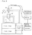
- the fiber-bundled convergent lens L similar to that used in Embodiment 1 is accommodated in the lens holder 3 made of metal. These two parts are then set on a fiber collimator set-up device shown in Fig. 6.
- the lens holder 3 is supported for movement in an X-axis direction and also in a Y-axis direction by means of X-axis and Y-axis stages, respectively, while the fiber holder H is supported for movement up and down, i.e., in a Z-axis direction by means of a Z-axis drive.
- Rays of light of 1.55 ⁇ m in wavelength are passed through the convergent lens L and towards the mirror 1.
- the light reflected from the mirror 1 enters the optical fiber 5 through the convergent lens L.
- the reflected light is then transmitted to a detector by means of a 3 db coupler.
- the amount of the reflected light detected by the detector for any particular position of the optical fiber 5 relative to the convergent lens L is processed according to and by a received light amount peak search software, i.e., a software designed to search for the peak value of the amount of the reflected light for each particular position, and subsequently, both of the convergent lens L and the single mode optical fiber are moved to respective positions at which the amount of the reflected light can be maximized.
- the fiber holder H and the lens holder 3 are fixedly welded together by means of a YAG laser Y thereby to provide a fiber collimator.
- the position of one of the lens and the optical fiber relative to the other of the lens and the optical fiber is adjusted and then fixed so that the beam of light which has emerged outwardly from the optical fiber and reflected back towards the optical fiber by the planar reflecting medium can be maximized. Therefore, the present invention is effective to accomplish a precise and simplified optical adjustment to provide the fiber-optic collimator which can be utilized to couple two optical fibers together at a reduced loss.
Landscapes
- Physics & Mathematics (AREA)
- General Physics & Mathematics (AREA)
- Optics & Photonics (AREA)
- Optical Couplings Of Light Guides (AREA)
Priority Applications (1)
| Application Number | Priority Date | Filing Date | Title |
|---|---|---|---|
| EP95106105A EP0695961B1 (fr) | 1990-10-09 | 1991-10-09 | Procédé pour la fabrication de collimateurs à fibre optique |
Applications Claiming Priority (2)
| Application Number | Priority Date | Filing Date | Title |
|---|---|---|---|
| JP2269606A JPH04146411A (ja) | 1990-10-09 | 1990-10-09 | ファイバコリメータの製造方法 |
| JP269606/90 | 1990-10-09 |
Related Child Applications (2)
| Application Number | Title | Priority Date | Filing Date |
|---|---|---|---|
| EP95106105A Division EP0695961B1 (fr) | 1990-10-09 | 1991-10-09 | Procédé pour la fabrication de collimateurs à fibre optique |
| EP95106105.0 Division-Into | 1995-04-24 |
Publications (3)
| Publication Number | Publication Date |
|---|---|
| EP0480401A2 true EP0480401A2 (fr) | 1992-04-15 |
| EP0480401A3 EP0480401A3 (en) | 1992-05-20 |
| EP0480401B1 EP0480401B1 (fr) | 1997-05-02 |
Family
ID=17474701
Family Applications (2)
| Application Number | Title | Priority Date | Filing Date |
|---|---|---|---|
| EP91117215A Expired - Lifetime EP0480401B1 (fr) | 1990-10-09 | 1991-10-09 | Procédé pour la fabrication de collinateurs à fibre optique |
| EP95106105A Expired - Lifetime EP0695961B1 (fr) | 1990-10-09 | 1991-10-09 | Procédé pour la fabrication de collimateurs à fibre optique |
Family Applications After (1)
| Application Number | Title | Priority Date | Filing Date |
|---|---|---|---|
| EP95106105A Expired - Lifetime EP0695961B1 (fr) | 1990-10-09 | 1991-10-09 | Procédé pour la fabrication de collimateurs à fibre optique |
Country Status (4)
| Country | Link |
|---|---|
| US (1) | US5265179A (fr) |
| EP (2) | EP0480401B1 (fr) |
| JP (1) | JPH04146411A (fr) |
| DE (2) | DE69125907T2 (fr) |
Families Citing this family (7)
| Publication number | Priority date | Publication date | Assignee | Title |
|---|---|---|---|---|
| AU651687B2 (en) * | 1991-05-20 | 1994-07-28 | Sumitomo Electric Industries, Ltd. | Method for screening optical fiber and apparatus for carrying out method |
| DE19549384C2 (de) * | 1995-06-19 | 1998-07-02 | Siemens Ag | Optischer Schalter |
| US6404955B1 (en) * | 2001-07-03 | 2002-06-11 | Corning, Incorporated | System and method for fabricating arrayed optical fiber collimators |
| KR100418713B1 (ko) * | 2002-02-15 | 2004-02-14 | 삼성전자주식회사 | 콜리메이터용 필터 결합장치 |
| US9921085B2 (en) | 2015-09-03 | 2018-03-20 | Honeywell Federal Manufacturing & Technologies, Llc | Method for active sensor signal optimization |
| EP3695257A1 (fr) * | 2018-07-30 | 2020-08-19 | Schleifring GmbH | Dispositif et procédé de soudage de fibres de verre à un réseau de microlentilles pour fabriquer un réseau de collimateurs de fibres |
| US11803018B2 (en) * | 2021-01-12 | 2023-10-31 | Hi Llc | Devices, systems, and methods with a piezoelectric-driven light intensity modulator |
Citations (1)
| Publication number | Priority date | Publication date | Assignee | Title |
|---|---|---|---|---|
| GB2089061A (en) * | 1980-12-04 | 1982-06-16 | Standard Telephones Cables Ltd | Optical fibre-beam expander alignment testing |
Family Cites Families (9)
| Publication number | Priority date | Publication date | Assignee | Title |
|---|---|---|---|---|
| DE1918612B1 (de) * | 1969-04-12 | 1969-12-04 | Carl Zeiss F | Beleuchtungseinrichtung |
| US4545643A (en) * | 1983-05-04 | 1985-10-08 | The United States Of America As Represented By The Secretary Of The Navy | Retro-reflective alignment technique for fiber optical connectors |
| GB2175411B (en) * | 1985-05-16 | 1988-08-03 | Stc Plc | Silica rod lens optical fibre terminations |
| US4770529A (en) * | 1986-09-08 | 1988-09-13 | Raychem Corp. | Alignment of optical waveguides |
| FR2627868B1 (fr) * | 1988-02-04 | 1993-09-24 | Comp Generale Electricite | Procede de couplage permanent d'une fibre optique a un composant, notamment a un laser semi-conducteur |
| DE3831839A1 (de) * | 1988-09-20 | 1990-03-29 | Standard Elektrik Lorenz Ag | Optischer sende- und/oder empfangsbaustein |
| CA2009129C (fr) * | 1989-02-04 | 1995-02-14 | Mitsubishi Chemical Corporation | Tete de capteur d'images |
| DK0421929T3 (da) * | 1989-10-03 | 1994-03-28 | Ciba Geigy Ag | Indretning til indføring af lysenergi fra en laserstråle i en fiberoptisk lysbølgeleder og fremgangsmåde til justering og overvågning af positionen af enden af den fiberoptiske lysbølgeleder |
| JPH06293627A (ja) * | 1993-02-12 | 1994-10-21 | Tsumura & Co | 湯水投入用組成物 |
-
1990
- 1990-10-09 JP JP2269606A patent/JPH04146411A/ja active Pending
-
1991
- 1991-10-04 US US07/770,868 patent/US5265179A/en not_active Expired - Fee Related
- 1991-10-09 DE DE69125907T patent/DE69125907T2/de not_active Expired - Fee Related
- 1991-10-09 EP EP91117215A patent/EP0480401B1/fr not_active Expired - Lifetime
- 1991-10-09 EP EP95106105A patent/EP0695961B1/fr not_active Expired - Lifetime
- 1991-10-09 DE DE69132720T patent/DE69132720T2/de not_active Expired - Fee Related
Patent Citations (1)
| Publication number | Priority date | Publication date | Assignee | Title |
|---|---|---|---|---|
| GB2089061A (en) * | 1980-12-04 | 1982-06-16 | Standard Telephones Cables Ltd | Optical fibre-beam expander alignment testing |
Also Published As
| Publication number | Publication date |
|---|---|
| EP0480401A3 (en) | 1992-05-20 |
| JPH04146411A (ja) | 1992-05-20 |
| DE69132720D1 (de) | 2001-10-11 |
| US5265179A (en) | 1993-11-23 |
| DE69132720T2 (de) | 2002-07-04 |
| DE69125907T2 (de) | 1997-09-25 |
| EP0695961B1 (fr) | 2001-09-05 |
| EP0480401B1 (fr) | 1997-05-02 |
| EP0695961A1 (fr) | 1996-02-07 |
| DE69125907D1 (de) | 1997-06-05 |
Similar Documents
| Publication | Publication Date | Title |
|---|---|---|
| US3938895A (en) | Method for positioning an optical fiber | |
| US5371814A (en) | Passive, multi-channel fiber optic rotary joint assembly | |
| US8254417B2 (en) | Fiber laser system with controllably alignable optical components thereof | |
| US4637683A (en) | Method for aligning optical fiber connectors | |
| US5760905A (en) | Distance measuring apparatus | |
| JPH0628612U (ja) | 多軸測定器 | |
| US4636030A (en) | Optical alignment apparatus utilizing prismatic elements | |
| US5265179A (en) | Method of manufacturing fiber-optic collimators | |
| CN115079346A (zh) | 一种空间光耦合至光纤的装调装置和方法 | |
| CA1196795A (fr) | Dispositif et methode d'epreuve de la qualite d'une lentille d'objectif | |
| RU2004005C1 (ru) | Устройство дл ввода лазерного излучени в волоконный световод и способ юстировки и контрол положени входного торца волоконного световода | |
| US5009482A (en) | Method and apparatus for fabricating a pigtailed lens assembly | |
| US6370299B1 (en) | Fiber optic collimation apparatus and associated method | |
| EP0210341B1 (fr) | Procédé et dispositif de mesure des pertes d'accouplement dans des fibres optiques à mode unique | |
| US4611115A (en) | Laser etch monitoring system | |
| CN214669715U (zh) | 一种探头用光纤一体化透镜及内窥镜成像系统 | |
| JP3343756B2 (ja) | 光回路用コリメータの製造方法 | |
| US4948984A (en) | Optical scanning head with objective position measuring and mirrors | |
| US20230305232A1 (en) | Method and system for aligning and positioning an optical fiber and microlens array | |
| JP3283575B2 (ja) | ファイバー端面測定装置 | |
| Lewis et al. | Interferometer light source and alignment aid using single-mode optical fibres | |
| US4850668A (en) | Gyroptic visual couplers | |
| JPH06129838A (ja) | 傾斜端を有する光ファイバの角度パラメータの測定方法及び該方法の実施に使用する装置 | |
| JPH08286076A (ja) | 広帯域光ファイバコリメータ | |
| JP2004279837A (ja) | ファイバコリメータの製造方法 |
Legal Events
| Date | Code | Title | Description |
|---|---|---|---|
| PUAI | Public reference made under article 153(3) epc to a published international application that has entered the european phase |
Free format text: ORIGINAL CODE: 0009012 |
|
| PUAL | Search report despatched |
Free format text: ORIGINAL CODE: 0009013 |
|
| AK | Designated contracting states |
Kind code of ref document: A2 Designated state(s): DE FR GB |
|
| AK | Designated contracting states |
Kind code of ref document: A3 Designated state(s): DE FR GB |
|
| 17P | Request for examination filed |
Effective date: 19920710 |
|
| 17Q | First examination report despatched |
Effective date: 19940428 |
|
| GRAG | Despatch of communication of intention to grant |
Free format text: ORIGINAL CODE: EPIDOS AGRA |
|
| GRAH | Despatch of communication of intention to grant a patent |
Free format text: ORIGINAL CODE: EPIDOS IGRA |
|
| GRAH | Despatch of communication of intention to grant a patent |
Free format text: ORIGINAL CODE: EPIDOS IGRA |
|
| GRAA | (expected) grant |
Free format text: ORIGINAL CODE: 0009210 |
|
| AK | Designated contracting states |
Kind code of ref document: B1 Designated state(s): DE FR GB |
|
| DX | Miscellaneous (deleted) | ||
| REF | Corresponds to: |
Ref document number: 69125907 Country of ref document: DE Date of ref document: 19970605 |
|
| ET | Fr: translation filed | ||
| PLBE | No opposition filed within time limit |
Free format text: ORIGINAL CODE: 0009261 |
|
| STAA | Information on the status of an ep patent application or granted ep patent |
Free format text: STATUS: NO OPPOSITION FILED WITHIN TIME LIMIT |
|
| 26N | No opposition filed | ||
| REG | Reference to a national code |
Ref country code: GB Ref legal event code: 746 Effective date: 19980331 |
|
| REG | Reference to a national code |
Ref country code: FR Ref legal event code: D6 |
|
| REG | Reference to a national code |
Ref country code: GB Ref legal event code: IF02 |
|
| PGFP | Annual fee paid to national office [announced via postgrant information from national office to epo] |
Ref country code: FR Payment date: 20021008 Year of fee payment: 12 |
|
| PGFP | Annual fee paid to national office [announced via postgrant information from national office to epo] |
Ref country code: GB Payment date: 20021009 Year of fee payment: 12 |
|
| PGFP | Annual fee paid to national office [announced via postgrant information from national office to epo] |
Ref country code: DE Payment date: 20021011 Year of fee payment: 12 |
|
| PG25 | Lapsed in a contracting state [announced via postgrant information from national office to epo] |
Ref country code: GB Free format text: LAPSE BECAUSE OF NON-PAYMENT OF DUE FEES Effective date: 20031009 |
|
| PG25 | Lapsed in a contracting state [announced via postgrant information from national office to epo] |
Ref country code: DE Free format text: LAPSE BECAUSE OF NON-PAYMENT OF DUE FEES Effective date: 20040501 |
|
| GBPC | Gb: european patent ceased through non-payment of renewal fee |
Effective date: 20031009 |
|
| PG25 | Lapsed in a contracting state [announced via postgrant information from national office to epo] |
Ref country code: FR Free format text: LAPSE BECAUSE OF NON-PAYMENT OF DUE FEES Effective date: 20040630 |
|
| REG | Reference to a national code |
Ref country code: FR Ref legal event code: ST |