EP0480321B1 - Wagon for transporting ballast - Google Patents
Wagon for transporting ballast Download PDFInfo
- Publication number
- EP0480321B1 EP0480321B1 EP91116935A EP91116935A EP0480321B1 EP 0480321 B1 EP0480321 B1 EP 0480321B1 EP 91116935 A EP91116935 A EP 91116935A EP 91116935 A EP91116935 A EP 91116935A EP 0480321 B1 EP0480321 B1 EP 0480321B1
- Authority
- EP
- European Patent Office
- Prior art keywords
- box
- conveyor belt
- waste material
- discharge conveyor
- railway wagon
- Prior art date
- Legal status (The legal status is an assumption and is not a legal conclusion. Google has not performed a legal analysis and makes no representation as to the accuracy of the status listed.)
- Expired - Lifetime
Links
Images

Classifications
-
- E—FIXED CONSTRUCTIONS
- E01—CONSTRUCTION OF ROADS, RAILWAYS, OR BRIDGES
- E01B—PERMANENT WAY; PERMANENT-WAY TOOLS; MACHINES FOR MAKING RAILWAYS OF ALL KINDS
- E01B27/00—Placing, renewing, working, cleaning, or taking-up the ballast, with or without concurrent work on the track; Devices therefor; Packing sleepers
- E01B27/02—Placing the ballast; Making ballastway; Redistributing ballasting material; Machines or devices therefor; Levelling means
-
- E—FIXED CONSTRUCTIONS
- E01—CONSTRUCTION OF ROADS, RAILWAYS, OR BRIDGES
- E01B—PERMANENT WAY; PERMANENT-WAY TOOLS; MACHINES FOR MAKING RAILWAYS OF ALL KINDS
- E01B2203/00—Devices for working the railway-superstructure
- E01B2203/03—Displacing or storing ballast
- E01B2203/032—Displacing or storing ballast with special use or configuration of conveyor belts
-
- E—FIXED CONSTRUCTIONS
- E01—CONSTRUCTION OF ROADS, RAILWAYS, OR BRIDGES
- E01B—PERMANENT WAY; PERMANENT-WAY TOOLS; MACHINES FOR MAKING RAILWAYS OF ALL KINDS
- E01B2203/00—Devices for working the railway-superstructure
- E01B2203/03—Displacing or storing ballast
- E01B2203/034—Displacing or storing ballast using storing containers
Definitions
- the present invention relates to a railroad car for the transport of overburden, according to the preamble of claim 1.
- railway wagons usually consist of two different parts: the first forms the organs for the movement of the wagon, d.s. the multitude of pairs of wheels running on rails; the second, on the other hand, consists of a "box" with high side walls that is open at the top and sits on a lower frame.
- This box forms the container for the overburden that is poured in from above by the excavator machines.
- a train in the working zone consisting of a series of such wagons which, after loading of the overburden has been loaded, are driven into an area that has been specially prepared for unloading the overburden.
- the railroad cars are usually provided with a series of telescopic arms, each operated by pneumatic pistons inserted between the lower frame and the "box".
- the operator actuates the pistons mentioned, which enable the box to be tilted to one side, so that the waste material can be emptied on one side thereof and deposited on the underlying floor.
- the object of the present invention is therefore to avoid the above-mentioned inadequacies by creating a railroad car for the transport of overburden, which is cheap and is provided with a combination of elements in its interior, which also rationally, quickly and conveniently load / unload the overburden allow previously unprepared soil.
- One of the advantages achieved with the present invention consists in the provision of a series of conveyor belts which ensure the rapid and efficient transport of the overburden brought into the box;
- the second movable and rotatable conveyor belt enables the overburden to be unloaded outside the railroad car, so that preparatory work with scraping buckets can be omitted.
- the railway car in question consists of a double pair of wheels 1, which can be moved on rails 21 and are connected by a horizontal flat bottom 2, on which an open-top box 3 is seated, which serves to receive the overburden, which in its entirety also includes 4 is designated.
- the box for receiving the overburden 4 is defined by a fixed structure consisting of the walls 3, a plurality of lids 7 to be opened and a closure bottom formed by the horizontal emptying belt 9.
- the conveyor belt 5 is arranged centrally and in the longitudinal direction on top of the box 3 and has an extension which is greater than the total length of the box.
- FIG. 1 shows that the two ends of the conveyor belt 5, each running around drums 5t, partially protrude from the box 3.
- a wedge-shaped element 6 Arranged above this conveyor belt 5 is a wedge-shaped element 6, which serves to displace the overburden 6 passing on the conveyor belt 5 and is horizontally movable over the entire longitudinal extent of the box 3 by means of slide devices 11.
- This wedge-shaped element 6 consists of a pair of opposing blades 6a and 6b, which form a wedge in plan.
- Said slide devices 11 consist of a pair of arms 11a and 11b (see FIG. 2) which form a frame which comprises the wedge-shaped element 6 on two sides and which are attached at one end to the articulated parallelogram 13 and, moreover, with small wheels at the other end 14a and 14b are provided, which on a pair of horizontal rails 15 run, which form part of the support frame of the conveyor belt 5 or alternatively can be provided at the upper end of the box 3 and which are arranged on opposite sides to the conveyor belt 5 and extend over the entire length of the box 3.
- the plurality of lids 7 are arranged in pairs opposite to each other and together with the end part of the box 3 form a corresponding row of funnel-shaped module units for receiving the overburden 4.
- These covers 7 can be moved by means of corresponding movement devices 12 between an extreme closed position of the module unit, in which each cover 7 is in contact with the end part of the box 3 without dissolving the continuity, and an open position of the module unit, in which each cover 7 is in one from the end part of the box 3 is located and consequently allows the inflow of overburden 4 over said end part of the box 3 also.
- the movement devices 12 consist of a hydraulic piston 16 for each of the existing covers 7, the ends of which are articulated on the inner part of the flat bottom 2 or on the cover 7.
- This emptying belt 9 can be pivoted about its own axis by means of movement devices 10 ⁇ which consist of a motor-driven turntable 17 which moves the aforementioned end (visible in FIG. 2) by an arc of approximately 180 ⁇ °.
- the turntable 17 swivels the discharge belt 9 between an inoperative position, in which the emptying belt 9 is arranged parallel to the flat bottom 2, and an unloading operating position for the waste material 4, in which the emptying belt 9 is arranged transversely and projecting to the flat bottom 2.
- the discharge belt 9 is protected by a trough frame 18 which completely encloses it, except, of course, the end of the discharge belt 9, which is intended for unloading the waste material 4 onto the underlying floor.
- the aforementioned devices for the movement 30 ⁇ and positioning 31 are - as can be seen well from FIGS. 1 and 2 - arranged below the box 3 and parallel to it over its entire length, in order gradually to act as the pivot point of the discharge belt 9 in the end Bring the area of the upper lid 7 located in the extreme open position.
- these devices for the movement 30 ⁇ and positioning 31 consist of a support carriage 32 for the emptying belt 9, which is inserted between the flat bottom 2 and the end of the emptying belt 9 which acts as a fulcrum and has on both sides a number of small wheels 33, which are in a pair run from mutually parallel guides 34 which are fastened on the flat floor 2 and extend over the entire length of the railroad car.
- the support carriage 32 is connected on both sides to an endless chain 35 which, for example, runs around sprockets (not shown here), which are provided at the relevant ends of the railway carriage, and is driven by means of a reduction gear 40 ⁇ which is arranged on the support carriage 32 to allow the displacement and positioning of the emptying belt 9 in the area of the cover 7, little by little as they open.
- the support carriage 32 can moreover be provided with path end devices which enable the support carriage to be stopped exactly in the region of the upper cover 7, which is in the extreme open position.
- the railway wagon designed in this way works in the following manner, assuming that a set of several railway wagons stands for loading the overburden in the loading zone: the machines provided for loading the overburden put it on the conveyor belt 5 of the first wagon and it is transported along the same.
- the wedge-shaped element 6 is arranged in a raised position by means of the articulated parallelogram 13, so that the waste material 4 can pass through to the last car.
- the wedge-shaped element 6 is in the position approximated to the conveyor belt 5 and in the region of the closing end of the box 3, in order in this way to cause the waste material 4 to fall down into the funnel-shaped module unit located underneath.
- the wedge-shaped element 6 is pushed forward in the direction C opposite to the direction of movement of the conveyor belt 5 (see arrows in FIG. 1), so that the inflow of waste material 4 into this last module unit is interrupted and with the filling in relation to the direction of movement of the overburden 4 in front of the module unit is started.
- the wedge-shaped element 6 of the following car is actuated, which begins with the filling phase of its module units as described above.
- the emptying belt 9 is pivoted by approximately 90 ° for each wagon, so that it is arranged on the side of the railway line on which the waste material 4 is intended to be unloaded.
- the various lids 7 are then opened in individual succession by means of the pistons 13, which allow the waste material 4 to be fed directly onto the emptying belt 9, from which it is then transported to the intended unloading point.
- the emptying belt 9 is brought under the next module by means of the support carriage 32, which in turn is moved by the chain (s) operated by a worker, in order to be able to empty the waste material 4 therefrom.
Landscapes
- Engineering & Computer Science (AREA)
- Architecture (AREA)
- Civil Engineering (AREA)
- Structural Engineering (AREA)
- Structure Of Belt Conveyors (AREA)
- Arc-Extinguishing Devices That Are Switches (AREA)
- Braking Arrangements (AREA)
- Vehicle Cleaning, Maintenance, Repair, Refitting, And Outriggers (AREA)
- Train Traffic Observation, Control, And Security (AREA)
- Filling Or Emptying Of Bunkers, Hoppers, And Tanks (AREA)
Abstract
Description
Die vorliegende Erfindung betrifft einen Eisenbahnwagen für den Transport von Abraumgut, nach dem Oberbegriff des Anspruches 1.The present invention relates to a railroad car for the transport of overburden, according to the preamble of
Auf dem Gebiet der Planung und der Konstruktion von Eisenbahnwagen sind einige Wagentypen für den Transport und das darauffolgende Abladen von Abraumgut von einer Arbeitszone in eine andere Ablagerungszone für das Abraumgut bekannt.In the field of planning and designing railway wagons, some types of wagons are known for the transport and subsequent unloading of waste material from one work zone to another deposit zone for the waste material.
Diese Eisenbahnwagen bestehen gewöhnlich aus zwei verschiedenen Teilen: der erste bildet die Organe für das Verfahren des Wagens, d.s. die Vielzahl von Räderpaaren, die auf Schienen laufen; der zweite hingegen besteht aus einem oben offenen "Kasten" mit hohen Seitenwänden, der auf einem unteren Rahmen aufsitzt.These railway wagons usually consist of two different parts: the first forms the organs for the movement of the wagon, d.s. the multitude of pairs of wheels running on rails; the second, on the other hand, consists of a "box" with high side walls that is open at the top and sits on a lower frame.
Dieser Kasten bildet den Behälter für das Abraumgut, das von oben von den Baggermaschinen eingeschüttet wird. Dabei befindet sich in der Arbeitszone ein Zug bestehend aus einer Reihe solcher Wagen, die, nach Beendigung der Beladung mit dem Abraumgut, in ein Gebiet gefahren werden, das eigens für das Abladen des Abraumgutes vorbereitet wurde.This box forms the container for the overburden that is poured in from above by the excavator machines. There is a train in the working zone consisting of a series of such wagons which, after loading of the overburden has been loaded, are driven into an area that has been specially prepared for unloading the overburden.
Für die Entladephase sind die Eisenbahnwagen gewöhnlich mit einer Reihe von Teleskoparmen versehen, die jeweils von zwischen dem unteren Rahmen und dem "Kasten" eingesetzten pneumatischen Kolben betätigt werden. Sobald der Wagen im Eentladegebiet ankommt, werden von der Bedienungsperson die genannten Kolben betätigt, welche das Kippen des Kastens nach einer Seite ermöglichen, um so das Abraumgut an einer Seite desselben auszuleeren und auf dem darunterliegenden Boden abzulagern.For the unloading phase, the railroad cars are usually provided with a series of telescopic arms, each operated by pneumatic pistons inserted between the lower frame and the "box". As soon as the wagon arrives in the unloading area, the operator actuates the pistons mentioned, which enable the box to be tilted to one side, so that the waste material can be emptied on one side thereof and deposited on the underlying floor.
Es ist diese Phase, in welcher sich einige, hauptsächlich auf die Bauweise des Wagens zurückzuführende Nachteile ergeben: einer betrifft die Langsamkeit, mit welcher das Kippen des Kastens erfolgt, um das Abraumgut zu entleeren, da das zu verschiebende Gewicht beachtlich ist und es daher ratsam ist, immer mit einer gewissen Vorsicht vorzugehen, damit es zu keinen Gleichgewichtsverschiebungen des einzelnen Wagens und auch des ganzen Zuges kommt. Ein weiterer Nachteil betrifft die Vorbereitung des Bodens, auf dem das Abraumgut abgeladen werden soll. Tatsächlich werden vorher, um keine Einsenkungen zu bilden, welche durch die Ablage des Aufschüttmaterials auf den ebenen Boden entstehen könnten, in der ganzen Abladezone Vertiefungen oder richtige Aushube vorbereitet, welche dazu bestimmt sind, vorübergehend das abgeladene Abraummaterial zu lagern, welches sodann durch Lastkraftwagen zur Weiterbeförderung in eine Dauerlagerung fortlaufend weggeführt wird.It is this phase in which there are some disadvantages, mainly due to the construction of the car: one concerns the slowness with which the box is tipped over to empty the waste material, since the weight to be moved is considerable and therefore advisable is always to proceed with a certain degree of caution so that there is no shift in the equilibrium of the individual wagon or the entire train. Another disadvantage concerns the preparation of the soil on which the waste material is to be dumped. In fact, in order not to form any depressions which could result from the depositing of the filling material on the flat floor, depressions or correct excavations are prepared in the entire unloading zone, which are intended to temporarily store the unloaded material, which is then used by trucks for Continued transport to permanent storage is continuously carried away.
Diese Vorgangsweise bringt jedoch einen bedeutenden Aufwand an Personal, Gerätschaft und Zeit und daher wirtschaftliche Belastungen für die die Arbeiten durchführende Baufirma mit sich.However, this procedure entails a significant expenditure of personnel, equipment and time and therefore economic burdens for the construction company carrying out the work.
Aufgabe der vorliegenden Erfindung ist daher die Vermeidung der genannten Unzulänglichkeiten durch Schaffung eines Eisenbahnwagens für den Transport von Abraumgut, der billig ist und in seinem Inneren mit einer Kombination von Elementen versehen ist, welche eine rationelle, rasche und bequeme Beladung/Entladung des Abraumgutes auch auf vorher nicht vorbereitetem Boden ermöglichen.The object of the present invention is therefore to avoid the above-mentioned inadequacies by creating a railroad car for the transport of overburden, which is cheap and is provided with a combination of elements in its interior, which also rationally, quickly and conveniently load / unload the overburden allow previously unprepared soil.
Diese Aufgabe wird erfindungsgemäß durch die Merkmale im Kennzeichnungsteil des Anspruches 1 gelöst.This object is achieved by the features in the characterizing part of
Einer der mit vorliegender Erfindung erzielten Vorteile besteht in der Vorsehung einer Reihe von Förderbändern, die für eine rasche und rationelle Beförderung des in den Kasten eingebrachten Abraumgutes sorgen; außerdem ermöglicht es das zweite bewegliche und drehbare Förderband, den Abraum außerhalb des Eisenbahnwagens abzuladen, so daß Vorbereitungsarbeiten mit Schürfkübeln entfallen können.One of the advantages achieved with the present invention consists in the provision of a series of conveyor belts which ensure the rapid and efficient transport of the overburden brought into the box; In addition, the second movable and rotatable conveyor belt enables the overburden to be unloaded outside the railroad car, so that preparatory work with scraping buckets can be omitted.
Die Erfindung wird in größerem Detail in der Folge unter Hinweis auf die beiliegenden Zeichnungen näher erläutert, welche eine rein beispielsweise und nicht einschränkende Ausführungsform hiervon zeigen, worin:
- die
Figuren 1 und 1a beide in Seitenansicht einen Eisenbahnwagen zeigen, wobei einige Teile zur besseren Darstellung anderer Teile weggelassen sind; - die
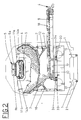
Figur 2 in Vorderansicht den Eisenbahnwagen gemäßFigur 1 zeigt, wobei einige Teile zur besseren Darstellung anderer Teile weggelassen sind.
- Figures 1 and 1a both show a side view of a railroad car, some parts being omitted for better illustration of other parts;
- FIG. 2 shows a front view of the railroad car according to FIG. 1, some parts being omitted for better illustration of other parts.
Gemäß den beiliegenden Zeichnungsfiguren besteht der gegenständliche Eisenbahnwagen aus einem Doppelpaar von Rädern 1, die auf Gleisen 21 verfahrbar und durch einen horizontalen Flachboden 2 verbunden sind, auf welchem ein oben offener Kasten 3 aufsitzt, der zur Aufnahme des Abraumgutes dient, das in seiner Gesamtheit mit 4 bezeichnet ist.According to the accompanying drawing figures, the railway car in question consists of a double pair of
Der Eisenbahnwagen weist eine Reihe von Elementen auf, die den Transport, die Beförderung und die darauffolgende Entladung von Abraummaterial ermöglichen und wie folgt zusammengefaßt werden können:
- ein
horizontales Förderband 5 für die Aufnahme von außen und den Transport desAbraumgutes 4; - eine Vielzahl von
Deckeln 7 für den Verschluß und die Öffnung des Kastens 3; - ein schwenkbares und unterhalb unter den
Deckeln 7 angeordneteshorizontales Entleerungsband 9 für die Aufnahme und die Entladung desAbraumgutes 4; - Einrichtung für die Bewegung 30̸ und
Positionierung 31 desEntleerungsbandes 9 im Bereich derDeckel 7.
- a
horizontal conveyor belt 5 for receiving from the outside and transporting the overburden 4; - a plurality of
lids 7 for the closure and opening of the box 3; - a pivotable and below the
lids 7 arrangedhorizontal emptying belt 9 for receiving and unloading the overburden 4; - Device for the movement 30̸ and positioning 31 of the
emptying belt 9 in the area of thecover 7.
Der Kasten für die Aufnahme des Abraumgutes 4 wird von einer fixen Struktur definiert, die aus den Wänden 3, einer Vielzahl von zu öffnenden Deckeln 7 und aus einem Verschlußboden, gebildet vom horizontalen Entleerungsband 9, besteht.The box for receiving the
Das Förderband 5 ist zentral und in Längsrichtung oben auf dem Kasten 3 angeordnet und hat eine Erstreckung, die größer ist als die Gesamtlänge des Kastens. Figur 1 kann entnommen werden, daß die beiden, jeweils um Trommeln 5t laufenden Enden des Förderbandes 5 teilweise aus dem Kasten 3 herausragen. Oberhalb dieses Förderbandes 5 ist ein keilförmiges Element 6 angeordnet, welches des Verschiebung des auf dem Förderband 5 vorbeilaufenden Abraumgutes 6 dient und über die ganze Längserstreckung des Kastens 3 mittels Schlitteneinrichtungen 11 horizontal beweglich ist. Dieses keilförmige Element 6 besteht aus einem Paar von einander gegenüberliegenden Klingen 6a und 6b, die im Grundriß einen Keil bilden. Diese Klingen 6a und 6b sind oben mit einem Gelenkparallelogramm 13 verbunden, das seinerseits an den vorgenannten Schlitteneinrichtungen 11 befestigt ist und welches dem keilförmigen Element 6 eine Höhenveränderung zwischen einer extrem an das Förderband 5 angenäherten Stellung und einer extrem von diesem Förderband 5 entfernten Stellung ermöglicht, wie in Fig. 1a strichliert gezeigt ist.The
Die genannten Schlitteneinrichtungen 11 bestehen aus einem Paar von Armen 11a und 11b (siehe Fig. 2), die einen Rahmen bilden, welcher zweiseitig das keilförmige Element 6 umfaßt, und welche mit einem Ende am Gelenkparallelogramm 13 befestigt und überdies am anderen Ende mit kleinen Rädern 14a und 14b versehen sind, welche auf einem Paar von horizontalen Schienen 15 laufen, die einen Teil des Stützrahmens des Förderbandes 5 bilden oder alternativ am oberen Ende des Kastens 3 vorgesehen werden können und welche an entgegengesetzten Seiten zum Förderband 5 angeordnet sind und sich über die ganze Länge des Kastens 3 erstrecken.Said
Aus Figur 2 kann ersehen werden, daß die Vielzahl von Deckeln 7 zu zweit einander gegenüberliegend angeordnet sind und zusammen mit dem Endteil des Kastens 3 eine entsprechende Reihe von trichterförmig ausgebildeten Moduleinheiten für die Aufnahme des Abraumgutes 4 bilden. Diese Deckel 7 sind mittels entsprechender Bewegungseinrichtungen 12 zwischen einer extremen Schließstellung der Moduleinheit, in welcher jeder der Deckel 7 ohne Auflösung der Kontinuität mit dem Endteil des Kastens 3 in Berührung befindet, und einer Offenstellung der Moduleinheit bewegbar, in welcher sich jeder Deckel 7 in einer vom Endteil des Kastens 3 abgesetzten Stellung befindet und folglich den Zufluß von Abraumgut 4 über den genannten Endteil des Kastens 3 hinaus ermöglicht. Die Bewegungseinrichtungen 12 bestehen im dargestellten Fall für jeden der vorhandenen Deckel 7 aus einem Hydraulikkolben 16, der mit seinen Enden am Innenteil des Flachbodens 2 bzw. am Deckel 7 angelenkt ist.From Figure 2 it can be seen that the plurality of
Unterhalb der Deckel 7 liegt das aktive Trum des mit seinem eigenen Ende als Drehpunkt fungierenden horizontalen Entleerungsbandes 9, das im Inneren des Kastens 3 angeordnet und insbesondere parallel und drehbar oberhalb des Flachbodens 2 befestigt ist. Dieses Entleerungsband 9 ist um eine eigene Achse mittels Bewegungseinrichtungen 10̸ schwenkbar, die aus einem motorgetriebenen Drehschemel 17 bestehen, der das vorgenannte Ende (sichtbar in Fig. 2) um einen Bogen von etwa 180̸° bewegt. Praktisch schwenkt der Drehschemel 17 das Entleerungsband 9 zwischen einer Außerbetriebsstellung, in welcher das Entleerungsband 9 parallel zum Flachboden 2 angeordnet ist, und einer Entlade-Betriebsstellung für das Abraumgut 4, in welcher das Entleerungsband 9 quer und vorspringend zum Flachboden 2 angeordnet ist. Um keine Verluste von herabfallendem Abraumgut zu verursachen, ist das Entleerungsband 9 von einem Muldenrahmen 18 geschützt, der es vollkommen einschließt, außer natürlich das Ende des Entleerungsbandes 9, welches zum Abladen des Abraumgutes 4 auf den darunterliegenden Boden bestimmt ist.Below the
Die vorgenannten Einrichtungen für die Bewegung 30̸ und Positionierung 31 sind - wie gut aus Fig. 1 und 2 ersichtlich - unterhalb des Kastens 3 und parallel zu diesem über seine ganze Länge angeordnet, um nach und nach das als Drehpunkt des Entleerungsbandes 9 fungierende Ende in den Bereich des sich in extremer Öffnungsstellung befindlichen oberen Deckels 7 zu bringen.The aforementioned devices for the movement 30̸ and positioning 31 are - as can be seen well from FIGS. 1 and 2 - arranged below the box 3 and parallel to it over its entire length, in order gradually to act as the pivot point of the
Insbesondere bestehen diese Einrichtungen für die Bewegung 30̸ und Positionierung 31 aus einem Auflagewagen 32 für das Entleerungsband 9, der zwischen dem Flachboden 2 und dem als Drehpunkt fungierenden Ende des Entleerungsbandes 9 eingesetzt ist und beidseitig eine Reihe von kleinen Rädern 33 besitzt, die in einem Paar von zueinander parallelen Führungen 34 laufen, welche auf dem Flachboden 2 befestigt sind und sich über die ganze Länge des Eisenbahnwagens erstrecken. Der Auflagewagen 32 ist beidseitig mit einer endlosen Kette 35 verbunden, die beispielsweise um Kettenscheiben (hier nicht gezeigt), die an den betreffenden Enden des Eisenbahnwagens vorgesehen sind, läuft und mittels eines Untersetzungsgetriebes 40̸ angetrieben wird, das auf dem Auflagewagen 32 angeordnet ist, um so die Verschiebung und Positionierung des Entleerungsbandes 9 im Bereich der Deckel 7, nach und nach wie sich diese öffnen, zu ermöglichen.In particular, these devices for the movement 30̸ and positioning 31 consist of a
Der Auflagewagen 32 kann überdies mit Wegendeinrichtungen versehen sein, die ein exaktes Anhalten des Auflagewagens im Bereich des oberen Deckels 7, der sich in extremer Öffnungsstellung befindet, zu ermöglichen.The
Der auf diese Weise ausgelegte Eisenbahnwagen funktioniert in folgender Weise, wobei angenommen wird, daß eine Garnitur von mehreren Eisenbahnwagen für das Aufladen des Abraumgutes in der Beladungszone steht: die zum Aufladen des Abraumgutes vorgesehenen Maschinen legen dieses auf das Förderband 5 des ersten Wagens auf und es wird entlang desselben befördert. Auf diesem Wagen und den folgenden, mit Ausnahme des letzten, ist das keilförmige Element 6 mittels des Gelenkparallelograms 13 in angehobener Stellung angeordnet, so daß das Abraumgut 4 bis zum letzten Wagen durchlaufen kann. Auf dem letzten Wagen befindet sich das keilförmige Element 6 in der zum Förderband 5 angenäherten Stellung und im Bereich des abschließenden Endes des Kastens 3, um auf diese Weise das Herabfallen des Abraumgutes 4 in die darunter befindliche, trichterförmige Moduleinheit zu bewirken.The railway wagon designed in this way works in the following manner, assuming that a set of several railway wagons stands for loading the overburden in the loading zone: the machines provided for loading the overburden put it on the
Sobald letztere gefüllt ist, wird das keilförmige Element 6 in Richtung C nach vorne entgegengesetzt zur Bewegungsrichtung des Förderbandes 5 geschoben (siehe Pfeile in Fig. 1), so daß der Zustrom von Abraumgut 4 in diese letzte Moduleinheit unterbrochen und mit der Füllung der in bezug auf die Bewegungsrichtung des Abraumgutes 4 davor befindlichen Moduleinheit begonnen wird. Nach dem vollständigen Füllen des ganzen Eisenbahnwagens wird das keilförmige Element 6 des folgenden Wagens betätigt, welche mit der Füllphase seiner Moduleinheiten wie oben beschrieben beginnt.As soon as the latter is filled, the wedge-
Nach dem Füllen der ganzen Reihe von Eisenbahnwagen wird der durch letztere gebildete Zug in den Abladesektor für das Abraumgut 4 gebracht. Nunmehr wird das Entleerungsband 9 bei jedem Wagen um etwa 90̸° verschwenkt, so daß es sich an der Seite der Eisenbahnstrecke anordnet, an welcher beabsichtigt ist, das Abraumgut 4 abzuladen. Hierauf werden in einzelner Aufeinanderfolge mittels der Kolben 13 die verschiedenen Deckel 7 geöffnet, welche den Zulauf des Abraumgutes 4 direkt auf das Entleerungsband 9 ermöglichen, von welchem es dann bis zu der beabsichtigten Abladestelle transportiert wird. Dabei wird das Entleerungsband 9, nachdem eine Moduleinheit entleert ist, mittels des Auflagewagens 32, der seinerseits von der oder den von einem Arbeiter betätigten Kette(n) bewegt wird, unter das nächste Modul gebracht, um daraus das Abraumgut 4 entleeren zu können.After filling the whole series of railroad cars, the brought by the latter train into the unloading sector for the
Aus den obigen Ausführungen kann man erkennen, daß der Entladungsvorgang sehr rasch erfolgt und daß somit die Wagen innerhalb eines sehr kurzen Zeitraumes viele Materialtransporte und -abladungen durchführen können.From the above, it can be seen that the unloading process takes place very quickly and that the wagons can therefore carry out and unload a lot of material within a very short period of time.
Um die Abladephase weiter zu beschleunigen, ist es möglich, ein weiteres, auf dem Boden aufgestelltes Transportband vorzusehen, mit welchem zusammen mit dem Entleerungsband 9 eine zusammenhängende Transportstrecke gebildet werden kann, die beispielsweise bis zu Transportlastwagen reicht, welche sodann das Abraumgut 4 zu den dafür vorgesehenen Sammelstellen befördern. Diese Maßnahme erweist sich dann als vorteilhaft, wenn auf einem Platz abgeladen werden soll, einem Ort, wo es nicht möglich ist, den Boden für die Aufnahme des Abraumgutes vorzubereiten.In order to further accelerate the unloading phase, it is possible to provide a further conveyor belt set up on the floor, with which a coherent transport route can be formed together with the
Claims (7)
- A railway wagon for transporting waste material, consisting of at least two pairs of wheels (1) running on tracks (21), which are connected by a flat floor (2) on which is mounted an open-topped box (3) intended for holding the waste material (4), characterized by- a horizontal conveyor belt (5), serving to receive from outside and to transport the waste material (4), which is arranged approximately centrally and in the longitudinal direction on top of the box (3), which box (3) is also provided with a wedge-shaped element (6) which is movable by means of sliding carriage devices (11) horizontally over the entire longitudinal extent of the box (3) and is arranged above and coaxially to the conveyor belt (5) and which is capable of moving the waste material (4), arriving on the conveyor belt (5), on either side and evenly into the interior of the box (3);- a plurality of covers (7) which are arranged in twos opposite one another and in the vicinity of the floor of the box (3), to form with the latter a corresponding series of modular units, designed in the form of hoppers, for holding the waste material (4), and which are movable, by means of corresponding operating mechanisms (12), between an extreme closed position of the modular unit, in which the covers (7) are in contact with the box (3) without destroying the continuity, and an extreme open position of the modular unit, in which the covers (7) are in a dropped-down position from the box and allow the waste material (4) to flow out of the same;- a horizontal discharge conveyor belt (9) for the waste material, the respective active side of which is arranged underneath the cover (7) so as to be coplanar, in order to receive and convey the waste material (4) dropping down from the modular units, and which is movable in the region of one of its ends acting as fulcrum about a vertical axis by means of turning mechanisms (10) between an inoperative position, in which the discharge conveyor belt (9) runs substantially parallel to the box (3), and an operative discharging position for the waste material (4), in which the discharge conveyor belt (9) is arranged approximately transversely and projecting in relation to the box (3);- mechanisms for moving (30) and positioning (31) which are arranged beneath the box (3) and parallel thereto over its whole length, and which are capable of moving the end acting as fulcrum of the discharge conveyor belt (9) progressively into the area of the upper cover (7) in the extreme opened position.
- A railway wagon according to claim 1, characterized in that the wedge-shaped element (6) consists of a pair of blades (6a and 6b) which, in plan view, form a wedge and are connected at the top to an articulated parallelogram (13) which is itself attached to the aforementioned sliding carriage devices (11) and which enables the wedge-shaped element (6) to vary its height between an extreme position close to the conveyor belt (5) and an extreme position remote from the conveyor belt (5).
- A railway wagon according to claim 1, characterized in that the sliding carriage devices (11) consist of a pair of arms (11a and 11b), one end of which is attached to an articulated parallelogram (13) and which are provided at the other end with wheels (14a and 14b) which run on a pair of horizontal rails (15) with which the top end of the box (3) is provided and which are arranged on opposite sides to the conveyor belt (5).
- A railway wagon according to claim 1, characterized in that the turning mechanisms (10) [sic, recte operating mechanisms (12)] for moving the covers (7) consist of respective hydraulic pistons (16), the ends of which are respectively linked to the inside part of the flat floor (2) and to the cover (7).
- A railway wagon according to claim 1, characterized in that the turning mechanisms (10) for moving the discharge conveyor belt (9) consist of a motor-driven turntable (17) which is fitted between the discharge conveyor belt (9), in the region of the end acting as fulcrum, and the mechanisms for moving (30) and positioning (31).
- A railway wagon according to claim 1, characterized in that the discharge conveyor belt (9) is provided with a trough frame (18) which encloses the discharge conveyor belt (9) completely.
- A railway wagon according to claim 1, characterized in that the mechanisms for moving (30) and positioning (31) consist of a supporting carriage (32) for the discharge conveyor belt (9), which is fitted between the flat floor (2) and the end acting as fulcrum of the discharge conveyor belt (9) and which has a series of wheels (33) running in a pair of mutually parallel guides (34) which are attached to the flat floor (2) and extend over the entire length of the railway wagon, the supporting carriage (32) being connected on either side to an endless chain (35) to enable the discharge conveyor belt (9) to be moved and positioned in the area of the covers (7).
Priority Applications (1)
| Application Number | Priority Date | Filing Date | Title |
|---|---|---|---|
| AT91116935T ATE102671T1 (en) | 1990-10-09 | 1991-10-04 | RAILWAY CARS FOR THE TRANSPORTATION OF WASTE MATERIAL. |
Applications Claiming Priority (2)
| Application Number | Priority Date | Filing Date | Title |
|---|---|---|---|
| IT368390 | 1990-10-09 | ||
| IT00368390A IT1242586B (en) | 1990-10-09 | 1990-10-09 | RAILWAY WAGON FOR DEBRIS TRANSPORT. |
Publications (2)
| Publication Number | Publication Date |
|---|---|
| EP0480321A1 EP0480321A1 (en) | 1992-04-15 |
| EP0480321B1 true EP0480321B1 (en) | 1994-03-09 |
Family
ID=11111370
Family Applications (1)
| Application Number | Title | Priority Date | Filing Date |
|---|---|---|---|
| EP91116935A Expired - Lifetime EP0480321B1 (en) | 1990-10-09 | 1991-10-04 | Wagon for transporting ballast |
Country Status (5)
| Country | Link |
|---|---|
| EP (1) | EP0480321B1 (en) |
| AT (1) | ATE102671T1 (en) |
| DE (1) | DE59101158D1 (en) |
| ES (1) | ES2050494T3 (en) |
| IT (1) | IT1242586B (en) |
Families Citing this family (4)
| Publication number | Priority date | Publication date | Assignee | Title |
|---|---|---|---|---|
| DE102005031413B4 (en) * | 2005-07-04 | 2009-06-25 | Oldenburg, Jörg, Prof. Dr. | Stepless electric transmission |
| EP1775190A3 (en) * | 2005-10-17 | 2007-06-20 | VolkerRail Nederland BV | Renewal of the ballast bed of a railway |
| WO2012110679A1 (en) | 2011-02-15 | 2012-08-23 | Metso Minerals, Inc. | Movable process device for mineral material processing |
| FR2988737B1 (en) * | 2012-03-29 | 2018-11-16 | Etf | DOUBLE FLOW BALLASTAGE TRAIN. |
Family Cites Families (2)
| Publication number | Priority date | Publication date | Assignee | Title |
|---|---|---|---|---|
| DE2146590A1 (en) * | 1970-09-17 | 1972-03-23 | Rossi, Lionello, Rom | Hopper trolleys with devices for automatic loading and unloading |
| DE2403010A1 (en) * | 1974-01-23 | 1975-07-31 | Wieger Maschbau | Viscous material loading and unloading machine - has lengthwise conveyor with transverse conveyor below, sliding in lengthwise direction |
-
1990
- 1990-10-09 IT IT00368390A patent/IT1242586B/en active IP Right Grant
-
1991
- 1991-10-04 EP EP91116935A patent/EP0480321B1/en not_active Expired - Lifetime
- 1991-10-04 DE DE91116935T patent/DE59101158D1/en not_active Expired - Lifetime
- 1991-10-04 AT AT91116935T patent/ATE102671T1/en not_active IP Right Cessation
- 1991-10-04 ES ES91116935T patent/ES2050494T3/en not_active Expired - Lifetime
Also Published As
| Publication number | Publication date |
|---|---|
| IT9003683A0 (en) | 1990-10-09 |
| ATE102671T1 (en) | 1994-03-15 |
| IT1242586B (en) | 1994-05-16 |
| IT9003683A1 (en) | 1992-04-09 |
| EP0480321A1 (en) | 1992-04-15 |
| DE59101158D1 (en) | 1994-04-14 |
| ES2050494T3 (en) | 1994-05-16 |
Similar Documents
| Publication | Publication Date | Title |
|---|---|---|
| DE3312492C2 (en) | ||
| DE68921108T2 (en) | Method and device for transporting materials. | |
| DE3711707A1 (en) | TRACKABLE DUMP CARGO LOADER WITH CONTROLLED UNLOADING CHEESES | |
| DE1456715A1 (en) | Bucket conveyor | |
| DE69927563T2 (en) | Automatic scales for fruits and the like | |
| EP0059984B1 (en) | Distributing device for a conveyor | |
| DE2109213B2 (en) | Bucket conveyor for bulk goods | |
| DE3228015A1 (en) | TRACKABLE PLANT FOR THE TRANSPORT OF SCHUETTGUT | |
| CH638848A5 (en) | SELF-DRIVING TRACK BED CLEANING MACHINE WITH DEVICES FOR RECEIVING, CLEANING, STORING AND RETURNING THE GRAVEL. | |
| EP0480321B1 (en) | Wagon for transporting ballast | |
| DE1456657B1 (en) | Device for clearing heaps | |
| DE69007216T2 (en) | Railway wagons for the transport of rubble. | |
| DE2628325A1 (en) | Canal bank surfacing machine supply unit - comprises mobile swivelling conveyor with closed heated space and storage container | |
| DE69708930T2 (en) | DEVICE AND METHOD FOR EMPTYING A FILLED CONTAINER | |
| WO1985003279A1 (en) | Method and plant for unloading bulk material from a large container | |
| DE3136316C2 (en) | Unloading device, in particular for receiving bulk goods from wagons or the like. | |
| DE4104877A1 (en) | Bulk material rail wagon - is open upwards and has delivery device running longitudinally in its lower part | |
| DE3332668C2 (en) | ||
| DE4213925A1 (en) | Goods waggon train for bulk goods transportation - consists of transship wagons with cantilever conveyor and movable base, and goods wagons with movable base | |
| DE68907355T2 (en) | Unloading freight on freight cars. | |
| DE2846789C2 (en) | De-storage device for clearing heaps of bulk material | |
| DE69300556T2 (en) | SELF-LOADING AND UNLOADING HIGH-BOARDED WAGON. | |
| DE69006626T2 (en) | Method and device for unloading boxes or the like | |
| DE8320290U1 (en) | Loading device for box-shaped large containers | |
| DE3519208A1 (en) | Bridge device for removing dumps of loose material |
Legal Events
| Date | Code | Title | Description |
|---|---|---|---|
| PUAI | Public reference made under article 153(3) epc to a published international application that has entered the european phase |
Free format text: ORIGINAL CODE: 0009012 |
|
| AK | Designated contracting states |
Kind code of ref document: A1 Designated state(s): AT BE DE ES FR GB NL |
|
| 17P | Request for examination filed |
Effective date: 19920803 |
|
| 17Q | First examination report despatched |
Effective date: 19930318 |
|
| GRAA | (expected) grant |
Free format text: ORIGINAL CODE: 0009210 |
|
| AK | Designated contracting states |
Kind code of ref document: B1 Designated state(s): AT BE DE ES FR GB NL |
|
| REF | Corresponds to: |
Ref document number: 102671 Country of ref document: AT Date of ref document: 19940315 Kind code of ref document: T |
|
| GBT | Gb: translation of ep patent filed (gb section 77(6)(a)/1977) |
Effective date: 19940314 |
|
| REF | Corresponds to: |
Ref document number: 59101158 Country of ref document: DE Date of ref document: 19940414 |
|
| REG | Reference to a national code |
Ref country code: ES Ref legal event code: FG2A Ref document number: 2050494 Country of ref document: ES Kind code of ref document: T3 |
|
| ET | Fr: translation filed | ||
| PLBE | No opposition filed within time limit |
Free format text: ORIGINAL CODE: 0009261 |
|
| STAA | Information on the status of an ep patent application or granted ep patent |
Free format text: STATUS: NO OPPOSITION FILED WITHIN TIME LIMIT |
|
| 26N | No opposition filed | ||
| REG | Reference to a national code |
Ref country code: GB Ref legal event code: IF02 |
|
| PGFP | Annual fee paid to national office [announced via postgrant information from national office to epo] |
Ref country code: AT Payment date: 20060912 Year of fee payment: 16 |
|
| PG25 | Lapsed in a contracting state [announced via postgrant information from national office to epo] |
Ref country code: AT Free format text: LAPSE BECAUSE OF NON-PAYMENT OF DUE FEES Effective date: 20071004 |
|
| PGFP | Annual fee paid to national office [announced via postgrant information from national office to epo] |
Ref country code: GB Payment date: 20090828 Year of fee payment: 19 |
|
| PGFP | Annual fee paid to national office [announced via postgrant information from national office to epo] |
Ref country code: ES Payment date: 20090922 Year of fee payment: 19 |
|
| PGFP | Annual fee paid to national office [announced via postgrant information from national office to epo] |
Ref country code: NL Payment date: 20090930 Year of fee payment: 19 Ref country code: BE Payment date: 20090925 Year of fee payment: 19 |
|
| PGFP | Annual fee paid to national office [announced via postgrant information from national office to epo] |
Ref country code: FR Payment date: 20091012 Year of fee payment: 19 |
|
| PGFP | Annual fee paid to national office [announced via postgrant information from national office to epo] |
Ref country code: DE Payment date: 20091217 Year of fee payment: 19 |
|
| BERE | Be: lapsed |
Owner name: FRANZ *PLASSER BAHNBAUMASCHINEN- INDUSTRIEGESELLSC Effective date: 20101031 |
|
| REG | Reference to a national code |
Ref country code: NL Ref legal event code: V1 Effective date: 20110501 |
|
| GBPC | Gb: european patent ceased through non-payment of renewal fee |
Effective date: 20101004 |
|
| PG25 | Lapsed in a contracting state [announced via postgrant information from national office to epo] |
Ref country code: FR Free format text: LAPSE BECAUSE OF NON-PAYMENT OF DUE FEES Effective date: 20101102 |
|
| REG | Reference to a national code |
Ref country code: FR Ref legal event code: ST Effective date: 20110630 |
|
| REG | Reference to a national code |
Ref country code: DE Ref legal event code: R119 Ref document number: 59101158 Country of ref document: DE Effective date: 20110502 |
|
| PG25 | Lapsed in a contracting state [announced via postgrant information from national office to epo] |
Ref country code: NL Free format text: LAPSE BECAUSE OF NON-PAYMENT OF DUE FEES Effective date: 20110501 Ref country code: BE Free format text: LAPSE BECAUSE OF NON-PAYMENT OF DUE FEES Effective date: 20101031 Ref country code: GB Free format text: LAPSE BECAUSE OF NON-PAYMENT OF DUE FEES Effective date: 20101004 |
|
| REG | Reference to a national code |
Ref country code: ES Ref legal event code: FD2A Effective date: 20111118 |
|
| PG25 | Lapsed in a contracting state [announced via postgrant information from national office to epo] |
Ref country code: ES Free format text: LAPSE BECAUSE OF NON-PAYMENT OF DUE FEES Effective date: 20101005 |
|
| PG25 | Lapsed in a contracting state [announced via postgrant information from national office to epo] |
Ref country code: DE Free format text: LAPSE BECAUSE OF NON-PAYMENT OF DUE FEES Effective date: 20110502 |