EP0480131A1 - Tilt switch - Google Patents
Tilt switch Download PDFInfo
- Publication number
- EP0480131A1 EP0480131A1 EP91110150A EP91110150A EP0480131A1 EP 0480131 A1 EP0480131 A1 EP 0480131A1 EP 91110150 A EP91110150 A EP 91110150A EP 91110150 A EP91110150 A EP 91110150A EP 0480131 A1 EP0480131 A1 EP 0480131A1
- Authority
- EP
- European Patent Office
- Prior art keywords
- tilt switch
- contact
- housing
- cone angle
- switch
- Prior art date
- Legal status (The legal status is an assumption and is not a legal conclusion. Google has not performed a legal analysis and makes no representation as to the accuracy of the status listed.)
- Withdrawn
Links
Images
Classifications
-
- H—ELECTRICITY
- H01—ELECTRIC ELEMENTS
- H01H—ELECTRIC SWITCHES; RELAYS; SELECTORS; EMERGENCY PROTECTIVE DEVICES
- H01H35/00—Switches operated by change of a physical condition
- H01H35/02—Switches operated by change of position, inclination or orientation of the switch itself in relation to gravitational field
Definitions
- the invention is based on a tilt switch according to the preamble of claim 1.
- Such an inclination switch which operates essentially reliably, but in which the distribution of the contact forces exerted by the ball over the two contact points is not adequately taken into account for the inclination angle at which the inclination switch makes contact.
- the invention has for its object to develop a tilt switch according to the preamble of claim 1 such that the contact is improved in the inclination range in which the contact is made, and that the contact force distribution in this area should be as even as possible at the two contact points.
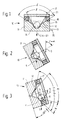
- 10 denotes an inclination switch with a housing-shaped first contact element 11 made of an electrically conductive material.
- the first contact element contains a first conical depression 12 with a cone angle ⁇ , which merges into a second conical depression 13 with a smaller cone angle ⁇ .
- a ball 14 made of electrically conductive material rests in the second conical depression 13 in the rest position of the tilt switch 10.
- the first contact element 11 has a first electrical connection 20 and the second contact element 17 has a second electrical connection 21.
- the operation of the tilt switch 10 according to FIGS. 1 to 3 is as follows.
- the cone angle ⁇ of the first conical depression 12 is ⁇ + 2 ⁇ , the angle ⁇ determining the distribution of the contact forces between the two contact points X, Y (FIG. 3).
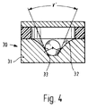
- a tilt switch 30 according to FIG. 4 has a similar structure to the tilt switch 10.
- the tilt switch 30 has a first housing-shaped contact part 31 which contains a rotationally symmetrical depression 32 in the form of a curve. Starting with an opening angle ⁇ 'at the bottom end 33 of the recess 32, the opening angle of the recess increases upwards, so that there is an effect similar to that of the recesses 12 and 13 according to FIG. 1.
- tilt switch is a so-called dead man's switch for radio devices to be held in the hand or worn on the body.
Landscapes
- Switches Operated By Changes In Physical Conditions (AREA)
- Rotary Switch, Piano Key Switch, And Lever Switch (AREA)
- Contacts (AREA)
Abstract
Description
Die Erfindung geht von einem Neigungsschalter nach dem Oberbegriff des Anspruchs 1 aus.The invention is based on a tilt switch according to the preamble of claim 1.
Es ist ein derartiger Neigungsschalter bekannt, der im wesentlichen betriebssicher arbeitet, bei dem aber die Aufteilung der durch die Kugel auf die beiden Kontaktstellen ausgeübten Kontaktkräfte für den Neigungswinkel, bei dem der Neigungsschalter Kontakt macht, nicht ausreichend berücksichtigt wird.Such an inclination switch is known which operates essentially reliably, but in which the distribution of the contact forces exerted by the ball over the two contact points is not adequately taken into account for the inclination angle at which the inclination switch makes contact.
Der Erfindung liegt die Aufgabe zugrunde, einen Neigungsschalter gemäß dem Oberbegriff des Anspruchs 1 derart weiterzubilden, daß die Kontaktgabe in demjenigen Neigungsbereich verbessert wird, in welchem die Kontaktgabe erfolgt, und zwar soll die Kontaktkraftverteilung in diesem Bereich an den beiden Kontaktstellen möglichst gleichmäßig sein.The invention has for its object to develop a tilt switch according to the preamble of claim 1 such that the contact is improved in the inclination range in which the contact is made, and that the contact force distribution in this area should be as even as possible at the two contact points.
Diese Aufgabe wird bei einem Neigungsschalter gemäß dem Oberbegriff des Anspruchs 1 durch die im kennzeichnenden Teil dieses Anspruchs angegebenen Merkmale gelöst. Der mit der Erfindung erzielbare Vorteil besteht insbesondere darin, daß eine möglichst optimale Kontaktdruckaufteilung an den beiden Kontaktstellen realisierbar ist.This object is achieved in a tilt switch according to the preamble of claim 1 by the features specified in the characterizing part of this claim. The advantage that can be achieved with the invention is, in particular, that the best possible contact pressure distribution can be achieved at the two contact points.
Zwei Ausführungsbeispiele der Erfindung sind in der Zeichnung an Hand mehrerer Figuren dargestellt und werden im folgenden näher erläutert.
Es zeigen
- Fig. 1
- eine Schnittansicht eines Neigungsschalters in aufrechter Stellung,
- Fig. 2
- eine Schnittansicht des Neigungsschalters nach Fig. 1 in etwas gekippter Stellung,
- Fig. 3
- eine Schnittansicht des Neigungsschalters nach Fig. 1 in einer weiter gekippten Stellung und
- Fig. 4
- eine Schnittansicht eines anderen Neigungsschalters in aufrechter Stellung.
Show it
- Fig. 1
- 2 shows a sectional view of an inclination switch in an upright position,
- Fig. 2
- 2 shows a sectional view of the tilt switch according to FIG. 1 in a somewhat tilted position,
- Fig. 3
- a sectional view of the tilt switch of FIG. 1 in a further tilted position and
- Fig. 4
- a sectional view of another tilt switch in the upright position.
In den Fig. 1 bis 3 bezeichnet 10 einen Neigungsschalter mit einem gehäuseförmigen ersten Kontaktelement 11 aus einem elektrisch leitenden Werkstoff. Das erste Kontaktelement enthält eine erste kegelförmige Vertiefung 12 mit einem Kegelwinkel δ, die in eine zweite kegelförmige Vertiefung 13 mit einem kleineren Kegelwinkel γ übergeht. In der zweiten kegelförmigen Vertiefung 13 ruht in der Ruhelage des Neigungsschalters 10 eine Kugel 14 aus elektrisch leitendem Werkstoff.1 to 3, 10 denotes an inclination switch with a housing-shaped
Ein dem Rand 15 an der Oberseite des ersten Kontaktelementes 11 angepaßter Ring 16 aus einem elektrisch isolierenden Werkstoff stellt eine mechanische Verbindung zwischen dem ersten Kontaktelement 11 und einem deckelförmigen zweiten Kontaktelement 17 her. Das erste Kontaktelement 11 weist einen ersten elektrischen Anschluß 20 und das zweite Kontaktelement 17 einen zweiten elektrischen Anschluß 21 auf.A
Die Wirkungsweise des Neigungsschalters 10 nach den Fig. 1 bis 3 ist folgende.The operation of the
In der Ruhestellung (Fig. 1) nimmt die Kugel 14 eine stabile Lage in der zweiten kegelförmigen Vertiefung 13 ein. Ein Winkel ε, der zwischen der Schwerkraftachse S und der Symmetrieachse des Neigungsschalters liegt, ist in der Ruhelage nach Fig. 1 gleich Null (ε = 0). Wird der Neigungsschalter aus seiner Ruhestellung nach Fig. 1 heraus so weit bewegt, daß der Neigungswinkel ε einen Winkel α (α = 90° - γ/2) geringfügig überschreitet, so beginnt die Kugel 14 zu rollen (Fig. 2). Wird der Neigungsschalter 10 dann noch weiter geneigt (ε > α), so rollt die Kugel 14 in eine Lage, in welcher sie die beiden Kontaktelemente 11 und 17 berührt. Der Kegelwinkel δ der ersten kegelförmigen Vertiefung 12 beträgt γ + 2β, wobei der Winkel β die Aufteilung der Kontaktkräfte auf die beiden Kontaktstellen X, Y (Fig. 3) bestimmt. Je größer der Winkel β gewählt wird, um so größer wird die auf die Kontaktstelle X am zweiten Kontaktelement 17 ausgeübte Kontaktkraft. Je weiter der Neigungsschalter 10 dann noch geneigt wird, um so gleichmäßiger teilen sich die von der Kugel 14 auf die beiden Kontaktstellen X und Y ausgeübten Kontaktkräfte auf.In the rest position (FIG. 1), the
Ein Neigungsschalter 30 nach Fig. 4 hat einen ähnlichen Aufbau wie der Neigungsschalter 10. Abweichend von dem Neigungsschalter 10 weist der Neigungsschalter 30 ein erstes gehäuseförmiges Kontaktteil 31 auf, das eine rotationssymmetrische Vertiefung 32 in Kurvenform enthält. Beginnend mit einem Öffnungswinkel γ' am bodenseitigen Ende 33 der Vertiefung 32 nimmt der Öffnungswinkel der Vertiefung nach oben zu, so daß sich ein ähnlicher Effekt wie bei den Vertiefungen 12 und 13 gemäß Fig. 1 ergibt.A
Eine vorteilhafte Anwendung für den Neigungsschalter ist ein sogenannter Totmannschalter für in der Hand zu haltende oder am Körper zu tragende Funkgeräte.An advantageous application for the tilt switch is a so-called dead man's switch for radio devices to be held in the hand or worn on the body.
Claims (3)
Applications Claiming Priority (2)
| Application Number | Priority Date | Filing Date | Title |
|---|---|---|---|
| DE19904031956 DE4031956A1 (en) | 1990-10-09 | 1990-10-09 | INCLINATION SWITCH |
| DE4031956 | 1990-10-09 |
Publications (1)
| Publication Number | Publication Date |
|---|---|
| EP0480131A1 true EP0480131A1 (en) | 1992-04-15 |
Family
ID=6415899
Family Applications (1)
| Application Number | Title | Priority Date | Filing Date |
|---|---|---|---|
| EP91110150A Withdrawn EP0480131A1 (en) | 1990-10-09 | 1991-06-20 | Tilt switch |
Country Status (3)
| Country | Link |
|---|---|
| EP (1) | EP0480131A1 (en) |
| JP (1) | JPH04249019A (en) |
| DE (1) | DE4031956A1 (en) |
Cited By (1)
| Publication number | Priority date | Publication date | Assignee | Title |
|---|---|---|---|---|
| US6559396B1 (en) * | 2002-06-13 | 2003-05-06 | Tien-Ming Chou | Tilt switch |
Families Citing this family (5)
| Publication number | Priority date | Publication date | Assignee | Title |
|---|---|---|---|---|
| US5837951A (en) * | 1992-09-16 | 1998-11-17 | Ubukata Industries Co., Ltd. | Inertia switching device, acceleration responsive device and method of making acceleration responsive device |
| US5600109A (en) * | 1993-10-01 | 1997-02-04 | Ubukata Industries Co., Ltd. | Acceleration responsive switch and method of making the same |
| JP2003157754A (en) * | 1992-09-26 | 2003-05-30 | Nittei Musen Kk | Inclination and vibration switch and inclination angle adjustment tool for the same |
| WO1994025974A1 (en) * | 1993-04-30 | 1994-11-10 | Fumio Nakajima | Inclination-vibration sensing switch |
| JP2863087B2 (en) * | 1994-05-24 | 1999-03-03 | 日東工器株式会社 | Vibration switch and portable electric device using the same |
Citations (4)
| Publication number | Priority date | Publication date | Assignee | Title |
|---|---|---|---|---|
| DE1132214B (en) * | 1959-05-26 | 1962-06-28 | Stanley Paul Clurman | Inertia switch with an inertia body made of electrically conductive material |
| DE3512486A1 (en) * | 1985-04-03 | 1986-10-16 | Dietmar 8500 Nürnberg Janus | Safety switch which is operated in a position-dependent manner |
| US4618746A (en) * | 1984-06-05 | 1986-10-21 | Seb S.A. | Ball actuated position sensitive switch |
| EP0223947A2 (en) * | 1985-10-28 | 1987-06-03 | Allied Corporation | Electrical tilt switch |
-
1990
- 1990-10-09 DE DE19904031956 patent/DE4031956A1/en not_active Withdrawn
-
1991
- 1991-06-20 EP EP91110150A patent/EP0480131A1/en not_active Withdrawn
- 1991-10-01 JP JP25323291A patent/JPH04249019A/en active Pending
Patent Citations (4)
| Publication number | Priority date | Publication date | Assignee | Title |
|---|---|---|---|---|
| DE1132214B (en) * | 1959-05-26 | 1962-06-28 | Stanley Paul Clurman | Inertia switch with an inertia body made of electrically conductive material |
| US4618746A (en) * | 1984-06-05 | 1986-10-21 | Seb S.A. | Ball actuated position sensitive switch |
| DE3512486A1 (en) * | 1985-04-03 | 1986-10-16 | Dietmar 8500 Nürnberg Janus | Safety switch which is operated in a position-dependent manner |
| EP0223947A2 (en) * | 1985-10-28 | 1987-06-03 | Allied Corporation | Electrical tilt switch |
Cited By (1)
| Publication number | Priority date | Publication date | Assignee | Title |
|---|---|---|---|---|
| US6559396B1 (en) * | 2002-06-13 | 2003-05-06 | Tien-Ming Chou | Tilt switch |
Also Published As
| Publication number | Publication date |
|---|---|
| JPH04249019A (en) | 1992-09-04 |
| DE4031956A1 (en) | 1992-04-16 |
Similar Documents
| Publication | Publication Date | Title |
|---|---|---|
| DE3213034A1 (en) | CONTROL WITH A CONTROL LEVER | |
| DE3922258C1 (en) | ||
| DE3201302A1 (en) | SCREW-HOLDING AND ALIGNING COVER PLATE | |
| DE19932951A1 (en) | Ball joint for damping fixing of two components on a car | |
| EP0480131A1 (en) | Tilt switch | |
| DE3910653C2 (en) | Passive infrared motion detectors | |
| EP0683906B1 (en) | Manual controller with control lever | |
| EP0463291A2 (en) | Tilt switch | |
| DE69422211T2 (en) | Delay switch | |
| DE69103941T2 (en) | Miniature switch with touch effect. | |
| DE2435637A1 (en) | SEMICONDUCTOR COMPONENT WITH PRESSURE CONTACT | |
| DE19519526A1 (en) | Glass facade panel holder | |
| DE3512486C2 (en) | ||
| EP0543093A2 (en) | Electrical switch | |
| DE2555867A1 (en) | LID FOR BRAKE FLUID RESERVOIR WITH A LEVEL INDICATOR | |
| WO2017152206A1 (en) | Electrode cap | |
| DE2505882A1 (en) | CHANGEABLE CAPACITOR | |
| WO2003096939A1 (en) | Endoprosthesis for replacing a joint, especially a shoulder joint | |
| DE3830108A1 (en) | Inclination transmitter | |
| DE2636164A1 (en) | ALL-DIRECTIONAL LOAD SWITCH | |
| EP0215486B1 (en) | Colour display tube | |
| DE9007264U1 (en) | Tilt switch | |
| DE2339711C2 (en) | Connection piece for the production of a bending moment-free, tensile strength, electrically conductive connection | |
| CH671480A5 (en) | ||
| DE2339076B1 (en) | Contact arrangement with shielding electrode |
Legal Events
| Date | Code | Title | Description |
|---|---|---|---|
| PUAI | Public reference made under article 153(3) epc to a published international application that has entered the european phase |
Free format text: ORIGINAL CODE: 0009012 |
|
| AK | Designated contracting states |
Kind code of ref document: A1 Designated state(s): DE FR IT |
|
| 17P | Request for examination filed |
Effective date: 19920715 |
|
| STAA | Information on the status of an ep patent application or granted ep patent |
Free format text: STATUS: THE APPLICATION HAS BEEN WITHDRAWN |
|
| 18W | Application withdrawn |
Withdrawal date: 19931115 |