EP0479564A2 - Fluid metering and coating device - Google Patents
Fluid metering and coating device Download PDFInfo
- Publication number
- EP0479564A2 EP0479564A2 EP19910309005 EP91309005A EP0479564A2 EP 0479564 A2 EP0479564 A2 EP 0479564A2 EP 19910309005 EP19910309005 EP 19910309005 EP 91309005 A EP91309005 A EP 91309005A EP 0479564 A2 EP0479564 A2 EP 0479564A2
- Authority
- EP
- European Patent Office
- Prior art keywords
- oil
- silicone rubber
- layer
- silicone
- porous
- Prior art date
- Legal status (The legal status is an assumption and is not a legal conclusion. Google has not performed a legal analysis and makes no representation as to the accuracy of the status listed.)
- Granted
Links
- 239000011248 coating agent Substances 0.000 title claims abstract description 19
- 238000000576 coating method Methods 0.000 title claims abstract description 19
- 239000012530 fluid Substances 0.000 title 1
- 239000007788 liquid Substances 0.000 claims abstract description 34
- 229920002379 silicone rubber Polymers 0.000 claims description 35
- 239000004945 silicone rubber Substances 0.000 claims description 35
- 229920002545 silicone oil Polymers 0.000 claims description 29
- 230000003014 reinforcing effect Effects 0.000 claims description 22
- 239000011148 porous material Substances 0.000 claims description 13
- 229920001187 thermosetting polymer Polymers 0.000 claims description 8
- 229920000295 expanded polytetrafluoroethylene Polymers 0.000 claims description 7
- 239000006260 foam Substances 0.000 abstract description 4
- 239000010410 layer Substances 0.000 description 41
- 239000000203 mixture Substances 0.000 description 18
- 239000000463 material Substances 0.000 description 17
- -1 polytetrafluoroethylene Polymers 0.000 description 6
- 229920001343 polytetrafluoroethylene Polymers 0.000 description 6
- 239000004810 polytetrafluoroethylene Substances 0.000 description 6
- 238000009987 spinning Methods 0.000 description 4
- 239000004640 Melamine resin Substances 0.000 description 3
- 229920000877 Melamine resin Polymers 0.000 description 3
- 239000000853 adhesive Substances 0.000 description 3
- 230000001070 adhesive effect Effects 0.000 description 3
- 230000015572 biosynthetic process Effects 0.000 description 3
- 239000003795 chemical substances by application Substances 0.000 description 3
- 230000002787 reinforcement Effects 0.000 description 3
- 229920005989 resin Polymers 0.000 description 3
- 239000011347 resin Substances 0.000 description 3
- 238000012883 sequential measurement Methods 0.000 description 3
- 238000004132 cross linking Methods 0.000 description 2
- 239000000835 fiber Substances 0.000 description 2
- 238000001879 gelation Methods 0.000 description 2
- 238000010438 heat treatment Methods 0.000 description 2
- 238000000034 method Methods 0.000 description 2
- 239000004634 thermosetting polymer Substances 0.000 description 2
- KXGFMDJXCMQABM-UHFFFAOYSA-N 2-methoxy-6-methylphenol Chemical compound [CH]OC1=CC=CC([CH])=C1O KXGFMDJXCMQABM-UHFFFAOYSA-N 0.000 description 1
- 229920000049 Carbon (fiber) Polymers 0.000 description 1
- 229920000784 Nomex Polymers 0.000 description 1
- 229910000831 Steel Inorganic materials 0.000 description 1
- 239000004917 carbon fiber Substances 0.000 description 1
- 230000005611 electricity Effects 0.000 description 1
- 230000002349 favourable effect Effects 0.000 description 1
- 239000003365 glass fiber Substances 0.000 description 1
- 238000007646 gravure printing Methods 0.000 description 1
- 239000002184 metal Substances 0.000 description 1
- 239000004763 nomex Substances 0.000 description 1
- 229920001568 phenolic resin Polymers 0.000 description 1
- 239000005011 phenolic resin Substances 0.000 description 1
- 229920001721 polyimide Polymers 0.000 description 1
- 239000009719 polyimide resin Substances 0.000 description 1
- 229920001296 polysiloxane Polymers 0.000 description 1
- 238000007790 scraping Methods 0.000 description 1
- 238000000926 separation method Methods 0.000 description 1
- 239000002356 single layer Substances 0.000 description 1
- 230000003068 static effect Effects 0.000 description 1
- 239000010959 steel Substances 0.000 description 1
- 238000005728 strengthening Methods 0.000 description 1
- 239000000126 substance Substances 0.000 description 1
- 230000037303 wrinkles Effects 0.000 description 1
Images
Classifications
-
- B—PERFORMING OPERATIONS; TRANSPORTING
- B05—SPRAYING OR ATOMISING IN GENERAL; APPLYING FLUENT MATERIALS TO SURFACES, IN GENERAL
- B05C—APPARATUS FOR APPLYING FLUENT MATERIALS TO SURFACES, IN GENERAL
- B05C1/00—Apparatus in which liquid or other fluent material is applied to the surface of the work by contact with a member carrying the liquid or other fluent material, e.g. a porous member loaded with a liquid to be applied as a coating
- B05C1/04—Apparatus in which liquid or other fluent material is applied to the surface of the work by contact with a member carrying the liquid or other fluent material, e.g. a porous member loaded with a liquid to be applied as a coating for applying liquid or other fluent material to work of indefinite length
- B05C1/08—Apparatus in which liquid or other fluent material is applied to the surface of the work by contact with a member carrying the liquid or other fluent material, e.g. a porous member loaded with a liquid to be applied as a coating for applying liquid or other fluent material to work of indefinite length using a roller or other rotating member which contacts the work along a generating line
- B05C1/0826—Apparatus in which liquid or other fluent material is applied to the surface of the work by contact with a member carrying the liquid or other fluent material, e.g. a porous member loaded with a liquid to be applied as a coating for applying liquid or other fluent material to work of indefinite length using a roller or other rotating member which contacts the work along a generating line the work being a web or sheets
- B05C1/083—Apparatus in which liquid or other fluent material is applied to the surface of the work by contact with a member carrying the liquid or other fluent material, e.g. a porous member loaded with a liquid to be applied as a coating for applying liquid or other fluent material to work of indefinite length using a roller or other rotating member which contacts the work along a generating line the work being a web or sheets being passed between the coating roller and one or more backing rollers
-
- G—PHYSICS
- G03—PHOTOGRAPHY; CINEMATOGRAPHY; ANALOGOUS TECHNIQUES USING WAVES OTHER THAN OPTICAL WAVES; ELECTROGRAPHY; HOLOGRAPHY
- G03G—ELECTROGRAPHY; ELECTROPHOTOGRAPHY; MAGNETOGRAPHY
- G03G15/00—Apparatus for electrographic processes using a charge pattern
- G03G15/20—Apparatus for electrographic processes using a charge pattern for fixing, e.g. by using heat
- G03G15/2003—Apparatus for electrographic processes using a charge pattern for fixing, e.g. by using heat using heat
- G03G15/2014—Apparatus for electrographic processes using a charge pattern for fixing, e.g. by using heat using heat using contact heat
- G03G15/2017—Structural details of the fixing unit in general, e.g. cooling means, heat shielding means
- G03G15/2025—Structural details of the fixing unit in general, e.g. cooling means, heat shielding means with special means for lubricating and/or cleaning the fixing unit, e.g. applying offset preventing fluid
-
- G—PHYSICS
- G03—PHOTOGRAPHY; CINEMATOGRAPHY; ANALOGOUS TECHNIQUES USING WAVES OTHER THAN OPTICAL WAVES; ELECTROGRAPHY; HOLOGRAPHY
- G03G—ELECTROGRAPHY; ELECTROPHOTOGRAPHY; MAGNETOGRAPHY
- G03G2215/00—Apparatus for electrophotographic processes
- G03G2215/20—Details of the fixing device or porcess
- G03G2215/2093—Release agent handling devices
- G03G2215/2096—Release agent handling devices using porous fluoropolymers for wicking the release agent
-
- Y—GENERAL TAGGING OF NEW TECHNOLOGICAL DEVELOPMENTS; GENERAL TAGGING OF CROSS-SECTIONAL TECHNOLOGIES SPANNING OVER SEVERAL SECTIONS OF THE IPC; TECHNICAL SUBJECTS COVERED BY FORMER USPC CROSS-REFERENCE ART COLLECTIONS [XRACs] AND DIGESTS
- Y10—TECHNICAL SUBJECTS COVERED BY FORMER USPC
- Y10S—TECHNICAL SUBJECTS COVERED BY FORMER USPC CROSS-REFERENCE ART COLLECTIONS [XRACs] AND DIGESTS
- Y10S118/00—Coating apparatus
- Y10S118/15—Roller structure
Definitions
- the present invention relates generally to materials and devices for coating controlled amounts of liquids on to rolls or other surfaces.
- toner images applied to the surface of paper or other recording medium are fixated by application of heat and pressure.
- fixation is accomplished by passing the image-bearing recording medium between a hot thermal-fixation roll and a pressure roll.
- thermal-fixation device When this type of thermal-fixation device is used the toner material is directly contacted by a roll surface and a portion of the toner adheres to the roll surface. With subsequent rotation of the roll the adhered toner material may be redeposited on the recording medium resulting in undesirable offset images, stains, or smears; or, in severe cases, the recording medium may stick to the adhered toner material on the roll and become wrapped around the roll.
- silicone rubber or polytetrafluoroethylene are often used for the roll surfaces. Although improving performance of the thermal fixation devices, use of silicone rubber or polytetrafluoroethylene roll surfaces alone do not eliminate the problems.
- Another approach used to counter the problems is to include release agents with the toner materials to prevent them from adhering to the roll surface. These oilless toners also improve performance of the thermal-fixation devices but again, particularly in the case of high-speed type copying machines, do not completely eliminate the problems associated with toner pickup and transfer.
- Toner pickup by the rolls can be controlled by coating the surface of at least one of the rolls of a thermal fixation device with a liquid release agent, such as a silicone oil. It is important that the release liquid be applied uniformly and in precise quantities to the surface of the roll. Too little liquid, or non-uniform surface coverage, will not prevent the toner from being picked up and redeposited on the roll. On the other hand, excessive quantities of the release liquid may cause silicone rubber roll surfaces to swell and wrinkle, thus producing copies of unacceptable quality. Furthermore, procedures intended to accommodate excess liquids by wiping or scraping them from the roll surface do not always produce favorable results and, in some cases, the efforts result in static electricity that cause further problems.
- a liquid release agent such as a silicone oil
- Devices to uniformly meter and coat a release liquid on copy machine roll surfaces are described in Japanese Laid-Open Patent No. 62-178992. These devices consist of an oil permeation control layer adhered to a thick porous material which serves as a wick or reservoir for supplying oil to the permeation control layer.
- the permeation control layer is typically a porous polytetrafluoroethylene film which has been impregnated with a mixture of silicone oil and silicone rubber followed by a heat treatment to crosslink the silicone rubber.
- the thick porous material to which the permeation control layer is adhered is typically porous polytetrafluoroethylene tubing or felts of Nomex (TM) fibers, glass fibers, carbon fibers, or polytetrafluoroethylene fibers.
- the devices described in Japanese Laid-Open Patent No. 62-178992 meter and uniformly coat roll surfaces with release liquids at rates of 0.3 to 1.0 microliters / A4 size paper copy. They have been used successfully in copying machines and provide satisfactory performance until approximately 80,000 to 180,000 copies have been made. At this time, usually due to deformation and failure of the thick porous material supporting the permeation control layer or to separation of the permeation control layer from the thick porous layer, they can no longer perform acceptably and must be replaced.
- This invention provides a liquid metering and surface coating device which can satisfactorily perform the operation of applying a release liquid, for example, to the surface of toner image fixation rolls in PPC copying, with exceptional accuracy, uniformity, and durability.
- the device comprises a liquid permeation control layer adhered to a porous support; said support comprising an open-celled thermosetting polymer foam internally reinforced to obtain the strength, resilience, and heat resistance needed for high durability in use as part of a hot toner image fixation mechanism in a PPC copying machine; said porous internally reinforced support comprising materials having high compatibility with and wettability by the liquids to be distributed and having high liquid holding capacity so as to provide smooth continuous liquid replenishment to the permeation control layer.
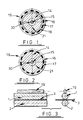
- FIG. 1 shows a preferred embodiment of the invention formed by first axially mounting a tubular porous support material 14 on a metal shaft 15.
- the porous support material should be an open-cell foam or other continuous pore structure having a pore volume of at least 40%, preferably in the range 80 to 99.9%. Materials with pore volume less than 40% have inadequate liquid-holding capacity and may have structures that restrict liquid movement through them. Materials with a pore volume over 99.9% have such an open, weak structure that, even with internal reinforcement, durability is too difficult to obtain.
- the porous support material should also be chemically compatible with and wettable by the liquids of use. The support material must also have sufficient rigidity, strength, and heat resistance that, when reinforced internally, permits operation at temperatures slightly over 200 C.
- Preferred materials are thermosetting polymer foams of melamine resin, polyimide resin, phenolic resin, or bismaleimidetriazine resin.
- a liquid permeation control layer 16 is prepared by adhering a porous material to the surface of the porous support material 14 using a thermosetting adhesive 17 applied to the surface by conventional means, for example, by gravure printing.
- a suitable porous material for the permeation control layer is porous polytetrafluoroethylene film, preferably porous expanded polytetrafluoroethylene film or, most preferably, porous expanded polytetrafluoroethylene film impregnated with a mixture of silicone oil and silicone rubber as described in Japanese Laid-Open Patent No. 62-178992.
- a reinforcing layer 18 is formed internally within the porous support 14 contiguous to the permeation control layer 16 by introducing a mixture of silicone oil and silicone rubber into the end of the porous support 14 and spinning the support about its axis, thus using centrifugal force to direct the mixture outwardly within the porous support to form a layer of uniform thickness contiguous with the inside surface of the permeation control layer 16, after which it is immobilized by crosslinking the silicone rubber.
- An oil supply layer 21 is then formed internally within the porous support 14 by introducing a second mixture of silicone oil and silicone rubber into the end of the porous support 14 and spinning the support about its axis, thus using centrifugal force to direct the mixture outwardly within the support to form a layer contiguous with the reinforcing layer 18 and leaving a small section 30 of the porous support 14 unfilled with the mixture. Gelation of the mixture forming the oil supply layer is then effected by crosslinking the silicone rubber.
- thermosetting resins in the open-cell, highly porous forms described above.
- the thermosetting resins although having desirable strength, rigidity, chemical and heat resistance properties would, in the open-cell highly porous forms needed for oil-holding capacity and oil delivery, be too weak for use without reinforcement.
- Discrete reinforcing layers in the porous support are required when the silicone oil to silicone rubber ratio is high, for example, 20:1. At such a concentration oil mobility is high but virtually no strengthening or toughening of the porous support is obtained and a separate reinforcing layer must be provided. As the silicone oil to silicone rubber ratio of the oil-supply layer becomes lower, the reinforcing effects of the crosslinked mixtures increase until, at a silicone oil to silicone rubber ratio of about 9:1, sufficient reinforcement to the porous support is obtained that a separate discrete reinforcing layer is unnecessary. In other words, at silicone oil to silicone rubber mixture ratios of about 9:1, it is possible to combine reinforcing and oil-supply functions in one layer.
- the liquid metering and coating device 19 of the invention is shown schematically as part of a toner image fixation mechanism of a PPC copying machine.
- the liquid metering and coating device 19 is shown in contact with the thermal fixation roll 1 against which a recording medium 3 carrying an unstabilized toner image is being forced by the pressure roll 2.
- a liquid metering and coating device 19 as shown in Figure 1 was prepared as follows:
- a mixture of two parts silicone oil (KF-96, manufactured by Shin-Etsu Chemical Co., Ltd. and used as a releasing agent) and eight parts silicone rubber (KE-106, manufactured by Shin-Etsu Chemical Co., Ltd.) was prepared.
- the porous expanded polytetrafluoroethylene film was impregnated with the silicone oil/silicone rubber mixture after which the excess mixture was removed from the film surface and the assembly heated at 150°C for 40 minutes, thus completing formation of the permeation control layer.
- the assembly was then heated at 150°C for 80 minutes to crosslink the silicone rubber and cause gelation in the oil-supply layer 21.
- the liquid metering and coating device was tested in a plain paper copying machine. Initially, the device applied oil at the rate of 0.1 microliter / A4 size copy. Oil application amounts of 0.1 to 0.2 microliters / A4 size copy were determined from sequential measurements of increments of 20,000 copies until 1,000,000 copies were made. No change in the appearance or shape of the device occurred.
- a liquid metering and coating device 19 having a combination reinforcing/oil-supply layer 22 of nine parts silicone oil to one part silicone rubber, and not having a discrete reinforcing layer, as shown in Figure 2 was formed from the same materials and by the methods described in Example 1 above.
- the liquid metering and coating device was tested in a plain paper copying machine. Initially, the device applied oil at the rate of 0.1 microliter / A4 size copy. Oil application amounts of 0/1 to 0.2 microliters / A4 size copy were determined from sequential measurements of increments of 20,000 copies until 500,000 copies were made. No change in the appearance or shape of the device occurred.
- the liquid metering and coating device was tested in a plain paper copying machine.
- the device applied oil at the rate of 0.2 microliters / A4 size copy.
- Oil application amounts of 0.2 to 0.3 microliters / A4 size copy were determined from sequential measurements of increments of 20,000 copies until 500,000 copies were made. No change in the appearance or shape of the device occurred.
Landscapes
- Physics & Mathematics (AREA)
- General Physics & Mathematics (AREA)
- Fixing For Electrophotography (AREA)
- Coating Apparatus (AREA)
Abstract
Description
- The present invention relates generally to materials and devices for coating controlled amounts of liquids on to rolls or other surfaces.
- In a plain-paper (PPC) copying machine toner images applied to the surface of paper or other recording medium are fixated by application of heat and pressure. In certain PPC copying machines fixation is accomplished by passing the image-bearing recording medium between a hot thermal-fixation roll and a pressure roll. When this type of thermal-fixation device is used the toner material is directly contacted by a roll surface and a portion of the toner adheres to the roll surface. With subsequent rotation of the roll the adhered toner material may be redeposited on the recording medium resulting in undesirable offset images, stains, or smears; or, in severe cases, the recording medium may stick to the adhered toner material on the roll and become wrapped around the roll.
- To counter these problems materials having good release properties such as silicone rubber or polytetrafluoroethylene are often used for the roll surfaces. Although improving performance of the thermal fixation devices, use of silicone rubber or polytetrafluoroethylene roll surfaces alone do not eliminate the problems. Another approach used to counter the problems is to include release agents with the toner materials to prevent them from adhering to the roll surface. These oilless toners also improve performance of the thermal-fixation devices but again, particularly in the case of high-speed type copying machines, do not completely eliminate the problems associated with toner pickup and transfer.
- Toner pickup by the rolls can be controlled by coating the surface of at least one of the rolls of a thermal fixation device with a liquid release agent, such as a silicone oil. It is important that the release liquid be applied uniformly and in precise quantities to the surface of the roll. Too little liquid, or non-uniform surface coverage, will not prevent the toner from being picked up and redeposited on the roll. On the other hand, excessive quantities of the release liquid may cause silicone rubber roll surfaces to swell and wrinkle, thus producing copies of unacceptable quality. Furthermore, procedures intended to accommodate excess liquids by wiping or scraping them from the roll surface do not always produce favorable results and, in some cases, the efforts result in static electricity that cause further problems.
- Devices to uniformly meter and coat a release liquid on copy machine roll surfaces are described in Japanese Laid-Open Patent No. 62-178992. These devices consist of an oil permeation control layer adhered to a thick porous material which serves as a wick or reservoir for supplying oil to the permeation control layer. The permeation control layer is typically a porous polytetrafluoroethylene film which has been impregnated with a mixture of silicone oil and silicone rubber followed by a heat treatment to crosslink the silicone rubber. The thick porous material to which the permeation control layer is adhered is typically porous polytetrafluoroethylene tubing or felts of Nomex (TM) fibers, glass fibers, carbon fibers, or polytetrafluoroethylene fibers.
- The devices described in Japanese Laid-Open Patent No. 62-178992 meter and uniformly coat roll surfaces with release liquids at rates of 0.3 to 1.0 microliters / A4 size paper copy. They have been used successfully in copying machines and provide satisfactory performance until approximately 80,000 to 180,000 copies have been made. At this time, usually due to deformation and failure of the thick porous material supporting the permeation control layer or to separation of the permeation control layer from the thick porous layer, they can no longer perform acceptably and must be replaced.
- This level of performance and durability is not satisfactory for many high-speed automated PPC copying machines for which release liquid metering and coating devices capable of delivering much smaller liquid quantities for much higher numbers of copies are needed.
- This invention provides a liquid metering and surface coating device which can satisfactorily perform the operation of applying a release liquid, for example, to the surface of toner image fixation rolls in PPC copying, with exceptional accuracy, uniformity, and durability.
- The device comprises a liquid permeation control layer adhered to a porous support; said support comprising an open-celled thermosetting polymer foam internally reinforced to obtain the strength, resilience, and heat resistance needed for high durability in use as part of a hot toner image fixation mechanism in a PPC copying machine; said porous internally reinforced support comprising materials having high compatibility with and wettability by the liquids to be distributed and having high liquid holding capacity so as to provide smooth continuous liquid replenishment to the permeation control layer.
-
- Figure 1 shows a cross-section of an embodiment of the invention.
- Figure 2 shows a cross-section of another embodiment of the invention.
- Figure 3 shows front and side schematic views of a toner fixation mechanism of a PPC copying machine incorporating an embodiment of the invention.
- Figure 1 shows a preferred embodiment of the invention formed by first axially mounting a tubular
porous support material 14 on ametal shaft 15. The porous support material should be an open-cell foam or other continuous pore structure having a pore volume of at least 40%, preferably in the range 80 to 99.9%. Materials with pore volume less than 40% have inadequate liquid-holding capacity and may have structures that restrict liquid movement through them. Materials with a pore volume over 99.9% have such an open, weak structure that, even with internal reinforcement, durability is too difficult to obtain. The porous support material should also be chemically compatible with and wettable by the liquids of use. The support material must also have sufficient rigidity, strength, and heat resistance that, when reinforced internally, permits operation at temperatures slightly over 200 C. Preferred materials are thermosetting polymer foams of melamine resin, polyimide resin, phenolic resin, or bismaleimidetriazine resin. - A liquid
permeation control layer 16 is prepared by adhering a porous material to the surface of theporous support material 14 using athermosetting adhesive 17 applied to the surface by conventional means, for example, by gravure printing. A suitable porous material for the permeation control layer is porous polytetrafluoroethylene film, preferably porous expanded polytetrafluoroethylene film or, most preferably, porous expanded polytetrafluoroethylene film impregnated with a mixture of silicone oil and silicone rubber as described in Japanese Laid-Open Patent No. 62-178992. - A reinforcing
layer 18 is formed internally within theporous support 14 contiguous to thepermeation control layer 16 by introducing a mixture of silicone oil and silicone rubber into the end of theporous support 14 and spinning the support about its axis, thus using centrifugal force to direct the mixture outwardly within the porous support to form a layer of uniform thickness contiguous with the inside surface of thepermeation control layer 16, after which it is immobilized by crosslinking the silicone rubber. - An
oil supply layer 21 is then formed internally within theporous support 14 by introducing a second mixture of silicone oil and silicone rubber into the end of theporous support 14 and spinning the support about its axis, thus using centrifugal force to direct the mixture outwardly within the support to form a layer contiguous with the reinforcinglayer 18 and leaving asmall section 30 of theporous support 14 unfilled with the mixture. Gelation of the mixture forming the oil supply layer is then effected by crosslinking the silicone rubber. - A key element leading to the invention was the discovery that significant strength can be developed in crosslinked mixtures of silicone oil and silicone rub- berwithout excessive loss of oil holding capacity or oil transfer properties. This discovery permits the use of the thermosetting resins in the open-cell, highly porous forms described above. The thermosetting resins, although having desirable strength, rigidity, chemical and heat resistance properties would, in the open-cell highly porous forms needed for oil-holding capacity and oil delivery, be too weak for use without reinforcement.
- The proportions of silicone oil and silicone rubber in the mixtures of the different layers will vary according to the amount of permeation required and to the structures and support materials with which they are used. Silicone oil to silicone rubber ratios may range from 50:1 to 1:20 and will be in the relationship:
a/x < = b/x < = c/x
where a, b, and c are the oil concentrations in the permeation control layer, reinforcing layer, and oil-supply layer respectively. - Discrete reinforcing layers in the porous support are required when the silicone oil to silicone rubber ratio is high, for example, 20:1. At such a concentration oil mobility is high but virtually no strengthening or toughening of the porous support is obtained and a separate reinforcing layer must be provided. As the silicone oil to silicone rubber ratio of the oil-supply layer becomes lower, the reinforcing effects of the crosslinked mixtures increase until, at a silicone oil to silicone rubber ratio of about 9:1, sufficient reinforcement to the porous support is obtained that a separate discrete reinforcing layer is unnecessary. In other words, at silicone oil to silicone rubber mixture ratios of about 9:1, it is possible to combine reinforcing and oil-supply functions in one layer.
- An embodiment of the invention combining reinforcing and oil-supply functions in a combination reinforcing/oil-supply layer 22, and not having a discrete reinforcing layer, but otherwise as described hereinabove, is shown in Figure 2.
- In Figure 3 the liquid metering and
coating device 19 of the invention is shown schematically as part of a toner image fixation mechanism of a PPC copying machine. The liquid metering andcoating device 19 is shown in contact with the thermal fixation roll 1 against which arecording medium 3 carrying an unstabilized toner image is being forced by thepressure roll 2. - The following examples further illustrate embodiments of the invention.
- A liquid metering and
coating device 19 as shown in Figure 1 was prepared as follows: - An 8 mm
diameter steel shaft 15 was inserted axially into a tubularporous support body 14 of melamine resin. The porous melamine resin body had an outer diameter of 27 mm, an inner diameter of 8 mm, and bulk density of 11 Kg/cubic meter. Thermosettingadhesive dots 17 having 0.5 mm diameters were gravure printed on theporous support body 14 after which formation of thepermeation control layer 16 was begun by wrapping a single layer of sintered porous expanded polytetrafluoroethylene film around theporous support body 14 and thermally fusing it in place with thethermosetting adhesive 17. The sintered porous expanded polytetrafluoroethylene film had a pore volume of 80%, a maximum pore size of 0.4 micrometers, and a thickness of 30 micrometers. - A mixture of two parts silicone oil (KF-96, manufactured by Shin-Etsu Chemical Co., Ltd. and used as a releasing agent) and eight parts silicone rubber (KE-106, manufactured by Shin-Etsu Chemical Co., Ltd.) was prepared. The porous expanded polytetrafluoroethylene film was impregnated with the silicone oil/silicone rubber mixture after which the excess mixture was removed from the film surface and the assembly heated at 150°C for 40 minutes, thus completing formation of the permeation control layer.
- A second mixture of the silicone oil and silicone rubber described above, in the ratio seven parts silicone oil to three parts silicone rubber, was poured into the end of the
porous support body 14 and, by spinning the assembly about its axis, was directed outwardly through the porous support body to form a reinforcinglayer 18 contiguous with thepermeation control layer 16. Formation of the reinforcinglayer 18 was completed by heating the assembly at 150°C for 80 minutes to crosslink the silicone rubber. - A third mixture of the silicone oil and silicone rubber described above, in the ratio nine parts silicone oil to one part silicone rubber, was poured into the end of the
porous support body 14 and, by spinning the assembly about its axis, was directed outwardly through the porous support body to form an oil-supply layer 21 contiguous with the reinforcinglayer 18 and leaving asmall section 30 of theporous support body 14 unfilled by the mixture. The assembly was then heated at 150°C for 80 minutes to crosslink the silicone rubber and cause gelation in the oil-supply layer 21. - The liquid metering and coating device was tested in a plain paper copying machine. Initially, the device applied oil at the rate of 0.1 microliter / A4 size copy. Oil application amounts of 0.1 to 0.2 microliters / A4 size copy were determined from sequential measurements of increments of 20,000 copies until 1,000,000 copies were made. No change in the appearance or shape of the device occurred.
- A liquid metering and
coating device 19 having a combination reinforcing/oil-supply layer 22 of nine parts silicone oil to one part silicone rubber, and not having a discrete reinforcing layer, as shown in Figure 2 was formed from the same materials and by the methods described in Example 1 above. - The liquid metering and coating device was tested in a plain paper copying machine. Initially, the device applied oil at the rate of 0.1 microliter / A4 size copy. Oil application amounts of 0/1 to 0.2 microliters / A4 size copy were determined from sequential measurements of increments of 20,000 copies until 500,000 copies were made. No change in the appearance or shape of the device occurred.
- A liquid metering and
coating device 19 having apermeation control layer 16 of sintered porous expanded polytetrafluoroethylene film only, but otherwise as described in Example 2 above, was formed. - The liquid metering and coating device was tested in a plain paper copying machine.
- Initially, the device applied oil at the rate of 0.2 microliters / A4 size copy. Oil application amounts of 0.2 to 0.3 microliters / A4 size copy were determined from sequential measurements of increments of 20,000 copies until 500,000 copies were made. No change in the appearance or shape of the device occurred.
Claims (5)
Applications Claiming Priority (2)
| Application Number | Priority Date | Filing Date | Title |
|---|---|---|---|
| JP02260513A JP3095765B2 (en) | 1990-10-01 | 1990-10-01 | Oil application roll for copier |
| JP260513/90 | 1990-10-01 |
Publications (3)
| Publication Number | Publication Date |
|---|---|
| EP0479564A2 true EP0479564A2 (en) | 1992-04-08 |
| EP0479564A3 EP0479564A3 (en) | 1992-10-14 |
| EP0479564B1 EP0479564B1 (en) | 1995-12-27 |
Family
ID=17349011
Family Applications (1)
| Application Number | Title | Priority Date | Filing Date |
|---|---|---|---|
| EP91309005A Expired - Lifetime EP0479564B1 (en) | 1990-10-01 | 1991-10-01 | Fluid metering and coating device |
Country Status (5)
| Country | Link |
|---|---|
| US (1) | US5232499A (en) |
| EP (1) | EP0479564B1 (en) |
| JP (1) | JP3095765B2 (en) |
| AU (1) | AU643322B2 (en) |
| DE (1) | DE69115825T2 (en) |
Cited By (10)
| Publication number | Priority date | Publication date | Assignee | Title |
|---|---|---|---|---|
| WO1993020483A1 (en) * | 1992-04-07 | 1993-10-14 | W.L. Gore & Associates (Uk) Ltd. | Oil reservoir |
| EP0616271A2 (en) * | 1993-03-19 | 1994-09-21 | Japan Gore-Tex, Inc. | A liquid metering and coating device |
| EP0619534A2 (en) * | 1993-04-08 | 1994-10-12 | Japan Gore-Tex, Inc. | An elastic fixing roll |
| EP0625735A1 (en) * | 1993-05-18 | 1994-11-23 | Japan Gore-Tex, Inc. | An elastic fixing roll |
| GB2265857B (en) * | 1992-04-07 | 1995-07-19 | Gore & Ass | Oil reservoir |
| EP0696766A1 (en) * | 1994-08-05 | 1996-02-14 | Japan Gore-Tex, Inc. | A liquid metering and coating apparatus |
| WO1997046918A1 (en) * | 1996-06-06 | 1997-12-11 | W.L. Gore & Associates, Inc. | Cleaner for critical imaging surfaces in various printer devices |
| US6143675A (en) * | 1995-06-07 | 2000-11-07 | W. L. Gore & Associates (Uk) Ltd. | Porous composite |
| US6212355B1 (en) | 1999-08-23 | 2001-04-03 | Tex Tech Industries | Oil metering supply apparatus and method for applying an evenly distributed release oil onto a fuser roller |
| WO2019115587A1 (en) * | 2017-12-14 | 2019-06-20 | Basf Se | Apparatus and process for impregnation of individual fibres, individual filaments or individual rovings |
Families Citing this family (28)
| Publication number | Priority date | Publication date | Assignee | Title |
|---|---|---|---|---|
| US5378281A (en) * | 1991-09-13 | 1995-01-03 | Kamata; Yoshiyuki | Pretreating apparatus for adhesion of plastic sheet materials |
| US5278617A (en) * | 1992-12-04 | 1994-01-11 | Xerox Corporation | Modified donor roll |
| US5478423A (en) * | 1993-09-28 | 1995-12-26 | W. L. Gore & Associates, Inc. | Method for making a printer release agent supply wick |
| AU8094194A (en) * | 1993-10-27 | 1995-05-22 | S.C. Johnson & Son, Inc. | Floor finish applicator |
| JP3337304B2 (en) * | 1994-02-23 | 2002-10-21 | 株式会社リコー | Fixing device |
| US5636012A (en) * | 1994-12-13 | 1997-06-03 | Konica Corporation | Toner image fixing device |
| US5974293A (en) * | 1994-12-15 | 1999-10-26 | Xerox Corporation | Donor brush with oil barrier layer |
| JPH08297427A (en) * | 1995-02-22 | 1996-11-12 | Japan Gore Tex Inc | Oil coating roll and oil-absorbing porous material used for that |
| US5800908A (en) * | 1995-06-07 | 1998-09-01 | W. L. Gore & Associates, Inc. | Oil delivery sheet material for use in various printer devices |
| US5779795A (en) * | 1995-08-04 | 1998-07-14 | W. L. Gore & Associates, Inc. | Low surface energy fluid metering and coating device |
| US5732317A (en) * | 1995-11-02 | 1998-03-24 | Eastman Kodak Company | Rotating wick device |
| JP2882767B2 (en) | 1995-12-28 | 1999-04-12 | 日東工業株式会社 | Oil coating roll for electrophotographic fixing and method for producing the same |
| DE69817160T2 (en) * | 1997-01-27 | 2004-06-09 | Bmp America Inc. | TEXTILES COATED WITH FLUOROCOLATED HYDROGEN PARTICLES FOR USE IN ELECTROSTATIC PRINTING DEVICES |
| US6750848B1 (en) | 1998-11-09 | 2004-06-15 | Timothy R. Pryor | More useful man machine interfaces and applications |
| US6168751B1 (en) | 1997-10-28 | 2001-01-02 | Ames Rubber Corporation | Method of making multilayer rolls having a thin fluoropolymer top coat |
| DE19757881A1 (en) * | 1997-12-24 | 1999-07-01 | Hausmann Joachim | Process and device for fiber impregnation |
| US6234625B1 (en) | 1998-06-26 | 2001-05-22 | Eastman Kodak Company | Printing apparatus with receiver treatment |
| JP4106170B2 (en) * | 1999-04-22 | 2008-06-25 | シンジーテック株式会社 | Oil application roller used in image forming apparatus |
| JP3910780B2 (en) * | 2000-04-20 | 2007-04-25 | 日東工業株式会社 | Image fixing unit |
| JP2002066413A (en) * | 2000-08-28 | 2002-03-05 | Nichias Corp | Oil coating apparatus |
| US6434358B1 (en) * | 2000-12-13 | 2002-08-13 | Lexmark International, Inc | Oil secreting supply roller for an electrophotographic printer, including a method for applying a toner repelling substance to a fuser roller |
| US6434357B1 (en) * | 2000-12-13 | 2002-08-13 | Lexmark International, Inc. | Oil exuding roller for an electrophotographic printer, including a method for its fabrication, and its function encompassed by a method for applying a toner repelling substance to a fuser roller |
| US7561841B2 (en) | 2005-12-21 | 2009-07-14 | Xerox Corporation | Cleaning system for a fuser apparatus |
| US7775324B2 (en) * | 2006-03-23 | 2010-08-17 | Thomas Peter Corden | Treadmill lubrication device |
| US8498559B2 (en) * | 2010-07-23 | 2013-07-30 | Xerox Corporation | Oil pressurized foam roll |
| US9069297B2 (en) | 2013-02-26 | 2015-06-30 | Lexmark International, Inc. | Self lubricating fuser and method of operation |
| US9075354B2 (en) | 2013-02-26 | 2015-07-07 | Lexmark International, Inc. | Self lubricating fuser and method of operation |
| US9146511B2 (en) * | 2013-04-25 | 2015-09-29 | Xerox Corporation | Fuser member |
Citations (5)
| Publication number | Priority date | Publication date | Assignee | Title |
|---|---|---|---|---|
| US4530140A (en) * | 1981-09-14 | 1985-07-23 | Minolta Camera K.K. | Offset preventive diffusing rollers for fixing rollers for electronic copying machines |
| JPS61148479A (en) * | 1984-12-21 | 1986-07-07 | Nitto Kogyo Kk | Supplying device for offset preventive oil of electronic copying machine |
| JPS61240266A (en) * | 1985-04-17 | 1986-10-25 | Sumitomo Electric Ind Ltd | Fixing device for copying machine or the like |
| JPS62178992A (en) * | 1986-02-03 | 1987-08-06 | Japan Gore Tex Inc | Oil applying mechanism for copying machine |
| JPS6431180A (en) * | 1987-07-27 | 1989-02-01 | Minolta Camera Kk | Nonadhesive elastic body roller for fixation |
Family Cites Families (11)
| Publication number | Priority date | Publication date | Assignee | Title |
|---|---|---|---|---|
| JPS5820033A (en) * | 1981-07-29 | 1983-02-05 | Toshiba Corp | Semiconductor integrated circuit |
| JPS59168479A (en) * | 1983-03-16 | 1984-09-22 | Canon Inc | Tube for attachment of roller for fixing device |
| FI840927A (en) * | 1984-03-07 | 1985-09-08 | Junkosha Co. Ltd. | FIXERINGSANORDNING FOER FAERGAEMNE I EN KOPIERINGSMASKIN. |
| JPS61151676A (en) * | 1984-12-26 | 1986-07-10 | Junkosha Co Ltd | Roller fixing device |
| JPS61183679A (en) * | 1985-02-09 | 1986-08-16 | Sumitomo Electric Ind Ltd | Mold releasing agent applying device |
| JPS61243836A (en) * | 1985-04-19 | 1986-10-30 | Yamauchi Rubber Ind Co Ltd | Production of silicone rubber roller |
| JPS61245178A (en) * | 1985-04-22 | 1986-10-31 | Sumitomo Electric Ind Ltd | Coating device for mold release agent |
| JPS63172186A (en) * | 1987-01-10 | 1988-07-15 | Sumitomo Electric Ind Ltd | Release agent coating roller |
| JPH01205188A (en) * | 1988-02-10 | 1989-08-17 | Minolta Camera Co Ltd | Fixing roller |
| JPH02308289A (en) * | 1989-05-24 | 1990-12-21 | Canon Inc | Image fixing device |
| JPH0812523B2 (en) * | 1989-05-31 | 1996-02-07 | キヤノン株式会社 | Fixing device |
-
1990
- 1990-10-01 JP JP02260513A patent/JP3095765B2/en not_active Expired - Fee Related
-
1991
- 1991-09-30 US US07/768,052 patent/US5232499A/en not_active Expired - Lifetime
- 1991-10-01 AU AU84898/91A patent/AU643322B2/en not_active Expired
- 1991-10-01 EP EP91309005A patent/EP0479564B1/en not_active Expired - Lifetime
- 1991-10-01 DE DE69115825T patent/DE69115825T2/en not_active Expired - Lifetime
Patent Citations (5)
| Publication number | Priority date | Publication date | Assignee | Title |
|---|---|---|---|---|
| US4530140A (en) * | 1981-09-14 | 1985-07-23 | Minolta Camera K.K. | Offset preventive diffusing rollers for fixing rollers for electronic copying machines |
| JPS61148479A (en) * | 1984-12-21 | 1986-07-07 | Nitto Kogyo Kk | Supplying device for offset preventive oil of electronic copying machine |
| JPS61240266A (en) * | 1985-04-17 | 1986-10-25 | Sumitomo Electric Ind Ltd | Fixing device for copying machine or the like |
| JPS62178992A (en) * | 1986-02-03 | 1987-08-06 | Japan Gore Tex Inc | Oil applying mechanism for copying machine |
| JPS6431180A (en) * | 1987-07-27 | 1989-02-01 | Minolta Camera Kk | Nonadhesive elastic body roller for fixation |
Non-Patent Citations (4)
| Title |
|---|
| PATENT ABSTRACTS OF JAPAN vol. 10, no. 348 (P-519)(2404) 22 November 1986 & JP-A-61 148 479 ( NITTO KOGYO K.K. ) 7 July 1986 * |
| PATENT ABSTRACTS OF JAPAN vol. 11, no. 87 (P-557)(2534) 17 March 1987 & JP-A-61 240 266 ( SUMITOMO ELECTRIC IND LTD ) 25 October 1986 * |
| PATENT ABSTRACTS OF JAPAN vol. 12, no. 25 (P-659)26 January 1988 & JP-A-62 178 992 ( JAPAN GORE TEX INC ) 6 August 1987 * |
| PATENT ABSTRACTS OF JAPAN vol. 13, no. 215 (P-874)19 May 1989 & JP-A-1 031 180 ( MINOLTA CAMERA ) 1 February 1989 * |
Cited By (16)
| Publication number | Priority date | Publication date | Assignee | Title |
|---|---|---|---|---|
| GB2265857B (en) * | 1992-04-07 | 1995-07-19 | Gore & Ass | Oil reservoir |
| US5534062A (en) * | 1992-04-07 | 1996-07-09 | W. L. Gore & Associates (Uk) Ltd. | Oil reservoir |
| WO1993020483A1 (en) * | 1992-04-07 | 1993-10-14 | W.L. Gore & Associates (Uk) Ltd. | Oil reservoir |
| EP0616271A2 (en) * | 1993-03-19 | 1994-09-21 | Japan Gore-Tex, Inc. | A liquid metering and coating device |
| EP0616271A3 (en) * | 1993-03-19 | 1998-03-04 | Japan Gore-Tex, Inc. | A liquid metering and coating device |
| EP0619534A2 (en) * | 1993-04-08 | 1994-10-12 | Japan Gore-Tex, Inc. | An elastic fixing roll |
| EP0619534A3 (en) * | 1993-04-08 | 1995-08-23 | Japan Gore Tex Inc | An elastic fixing roll. |
| EP0625735A1 (en) * | 1993-05-18 | 1994-11-23 | Japan Gore-Tex, Inc. | An elastic fixing roll |
| US5868839A (en) * | 1994-08-05 | 1999-02-09 | Japan Gore-Tex, Inc. | Liquid metering and coating assembly |
| EP0696766A1 (en) * | 1994-08-05 | 1996-02-14 | Japan Gore-Tex, Inc. | A liquid metering and coating apparatus |
| US6143675A (en) * | 1995-06-07 | 2000-11-07 | W. L. Gore & Associates (Uk) Ltd. | Porous composite |
| US6041211A (en) * | 1996-06-06 | 2000-03-21 | W. L. Gore & Associates, Inc. | Cleaning assembly for critical image surfaces in printer devices and method of using same |
| WO1997046918A1 (en) * | 1996-06-06 | 1997-12-11 | W.L. Gore & Associates, Inc. | Cleaner for critical imaging surfaces in various printer devices |
| US6212355B1 (en) | 1999-08-23 | 2001-04-03 | Tex Tech Industries | Oil metering supply apparatus and method for applying an evenly distributed release oil onto a fuser roller |
| WO2019115587A1 (en) * | 2017-12-14 | 2019-06-20 | Basf Se | Apparatus and process for impregnation of individual fibres, individual filaments or individual rovings |
| US11273578B2 (en) | 2017-12-14 | 2022-03-15 | Basf Se | Device and method for impregnating individual fibers, individual threads, or individual rovings |
Also Published As
| Publication number | Publication date |
|---|---|
| AU8489891A (en) | 1992-04-02 |
| EP0479564B1 (en) | 1995-12-27 |
| DE69115825D1 (en) | 1996-02-08 |
| JPH04139477A (en) | 1992-05-13 |
| AU643322B2 (en) | 1993-11-11 |
| DE69115825T2 (en) | 1996-05-15 |
| JP3095765B2 (en) | 2000-10-10 |
| US5232499A (en) | 1993-08-03 |
| EP0479564A3 (en) | 1992-10-14 |
Similar Documents
| Publication | Publication Date | Title |
|---|---|---|
| EP0479564B1 (en) | Fluid metering and coating device | |
| EP0616271B1 (en) | A liquid metering and coating device | |
| EP0842457B1 (en) | Low surface energy fluid metering and coating device | |
| EP0625735B1 (en) | An elastic fixing roll | |
| US3964431A (en) | Device for supplying an offset preventing liquid to a fixing roller | |
| US4887340A (en) | Elastic fixing roller | |
| US5788770A (en) | Oil delivery sheet material for use in various printer devices | |
| US6336972B1 (en) | Oil coating apparatus | |
| EP1069369B1 (en) | Oil application apparatus | |
| US5868839A (en) | Liquid metering and coating assembly | |
| CA1184236A (en) | Fixing apparatus | |
| EP0729080B1 (en) | Release liquid supply device and liquid absorbing material for use therein | |
| EP1243980A1 (en) | Oil coating roller, seal ring used for the roller, and fixing device using the seal ring | |
| US5534062A (en) | Oil reservoir | |
| US6212355B1 (en) | Oil metering supply apparatus and method for applying an evenly distributed release oil onto a fuser roller | |
| JPS62178992A (en) | Oil applying mechanism for copying machine | |
| JPH063398Y2 (en) | Pressure roller for fixing | |
| GB2265857A (en) | Oil reservoir | |
| JPH08190297A (en) | Apparatus and method for sticking of offset-preventive liquid to fuser roll |
Legal Events
| Date | Code | Title | Description |
|---|---|---|---|
| PUAI | Public reference made under article 153(3) epc to a published international application that has entered the european phase |
Free format text: ORIGINAL CODE: 0009012 |
|
| AK | Designated contracting states |
Kind code of ref document: A2 Designated state(s): DE FR GB IT SE |
|
| RIN1 | Information on inventor provided before grant (corrected) |
Inventor name: KIKUKAWA, HIROYASU Inventor name: KATO, HIROSHI |
|
| PUAL | Search report despatched |
Free format text: ORIGINAL CODE: 0009013 |
|
| AK | Designated contracting states |
Kind code of ref document: A3 Designated state(s): DE FR GB IT SE |
|
| 17P | Request for examination filed |
Effective date: 19930311 |
|
| 17Q | First examination report despatched |
Effective date: 19950321 |
|
| GRAA | (expected) grant |
Free format text: ORIGINAL CODE: 0009210 |
|
| AK | Designated contracting states |
Kind code of ref document: B1 Designated state(s): DE FR GB IT SE |
|
| ITF | It: translation for a ep patent filed | ||
| REF | Corresponds to: |
Ref document number: 69115825 Country of ref document: DE Date of ref document: 19960208 |
|
| ET | Fr: translation filed | ||
| PLBE | No opposition filed within time limit |
Free format text: ORIGINAL CODE: 0009261 |
|
| STAA | Information on the status of an ep patent application or granted ep patent |
Free format text: STATUS: NO OPPOSITION FILED WITHIN TIME LIMIT |
|
| 26N | No opposition filed | ||
| REG | Reference to a national code |
Ref country code: GB Ref legal event code: IF02 |
|
| PGFP | Annual fee paid to national office [announced via postgrant information from national office to epo] |
Ref country code: FR Payment date: 20101105 Year of fee payment: 20 |
|
| PGFP | Annual fee paid to national office [announced via postgrant information from national office to epo] |
Ref country code: DE Payment date: 20101027 Year of fee payment: 20 |
|
| PGFP | Annual fee paid to national office [announced via postgrant information from national office to epo] |
Ref country code: GB Payment date: 20101025 Year of fee payment: 20 Ref country code: SE Payment date: 20101027 Year of fee payment: 20 Ref country code: IT Payment date: 20101027 Year of fee payment: 20 |
|
| REG | Reference to a national code |
Ref country code: DE Ref legal event code: R071 Ref document number: 69115825 Country of ref document: DE |
|
| REG | Reference to a national code |
Ref country code: DE Ref legal event code: R071 Ref document number: 69115825 Country of ref document: DE |
|
| REG | Reference to a national code |
Ref country code: GB Ref legal event code: PE20 Expiry date: 20110930 |
|
| REG | Reference to a national code |
Ref country code: SE Ref legal event code: EUG |
|
| PG25 | Lapsed in a contracting state [announced via postgrant information from national office to epo] |
Ref country code: GB Free format text: LAPSE BECAUSE OF EXPIRATION OF PROTECTION Effective date: 20110930 |
|
| PG25 | Lapsed in a contracting state [announced via postgrant information from national office to epo] |
Ref country code: DE Free format text: LAPSE BECAUSE OF EXPIRATION OF PROTECTION Effective date: 20111002 |