EP0479543A2 - Gewinnung von seismischen Daten von einem Bohrloch - Google Patents
Gewinnung von seismischen Daten von einem Bohrloch Download PDFInfo
- Publication number
- EP0479543A2 EP0479543A2 EP91308959A EP91308959A EP0479543A2 EP 0479543 A2 EP0479543 A2 EP 0479543A2 EP 91308959 A EP91308959 A EP 91308959A EP 91308959 A EP91308959 A EP 91308959A EP 0479543 A2 EP0479543 A2 EP 0479543A2
- Authority
- EP
- European Patent Office
- Prior art keywords
- data
- memory
- well borehole
- seismic
- signal
- Prior art date
- Legal status (The legal status is an assumption and is not a legal conclusion. Google has not performed a legal analysis and makes no representation as to the accuracy of the status listed.)
- Withdrawn
Links
Images
Classifications
-
- G—PHYSICS
- G01—MEASURING; TESTING
- G01V—GEOPHYSICS; GRAVITATIONAL MEASUREMENTS; DETECTING MASSES OR OBJECTS; TAGS
- G01V1/00—Seismology; Seismic or acoustic prospecting or detecting
- G01V1/40—Seismology; Seismic or acoustic prospecting or detecting specially adapted for well-logging
- G01V1/42—Seismology; Seismic or acoustic prospecting or detecting specially adapted for well-logging using generators in one well and receivers elsewhere or vice versa
-
- Y—GENERAL TAGGING OF NEW TECHNOLOGICAL DEVELOPMENTS; GENERAL TAGGING OF CROSS-SECTIONAL TECHNOLOGIES SPANNING OVER SEVERAL SECTIONS OF THE IPC; TECHNICAL SUBJECTS COVERED BY FORMER USPC CROSS-REFERENCE ART COLLECTIONS [XRACs] AND DIGESTS
- Y10—TECHNICAL SUBJECTS COVERED BY FORMER USPC
- Y10S—TECHNICAL SUBJECTS COVERED BY FORMER USPC CROSS-REFERENCE ART COLLECTIONS [XRACs] AND DIGESTS
- Y10S367/00—Communications, electrical: acoustic wave systems and devices
- Y10S367/911—Particular well-logging apparatus
- Y10S367/912—Particular transducer
Definitions
- the present invention relates to a method and apparatus for obtaining seismic data from a well borehole.
- VSP logging One known well logging technique is generally identified as VSP logging and involves a process whereby a sound source such as a vibrator or explosive charge is operated from the surface, sonic shock waves are then transmitted from the surface through multiple layers of the earth's crust, and the shock waves are reflected at various interfaces.
- a sensor is positioned in a well near the shock source. The sonic signals travel downwardly and reflect back toward the surface where they are intercepted and data is recorded from various geophone locations along the well.
- a crosswell survey involves positioning a sound source in an adjacent well, perhaps spaced apart by a few hundred feet, or even a few thousand feet from a well in which a sensor is positioned (1 foot is 0.3m).
- a method of obtaining seismic data from a remote seismic source in a well borehole wherein the method comprises:
- the invention also includes apparatus for use in obtaining seismic data from a well borehole, which apparatus comprises:
- clusters of displacement transducers are arranged in mutually orthogonal directions to provide three coordinate resolution of the sonic signal of interest.
- the cluster can be placed in a housing supporting the three sensors for installation at a particular depth. This is replicated at selected spacings along the well, for instance separate recording stations at a spacing of twenty-five feet (7.62m). If only two or three sets of equipment are included, the data obtained from simultaneous operation is substantial, but it might possibly be transmitted to the surface through a conventional telemetry system; however, when the number of recording stations increases, data recovery is markedly increased far beyond what can be handled in logging cable telemetry.
- the present invention provides a telemetry mechanism which enables recovery of the data.
- It also provides a common bus system from the stations which are deployed or spread along the well to transmit the data from the respective sensors to a main telemetry unit, and thereafter enables transmission to the surface.
- the telemetry system in the main unit will interrogate each of the appended seismic recording stations and obtain the necessary data. This is sequentially carried out until all the data has been transmitted to a memory in the main unit.
- data is transmitted from the main unit by telemetry to the surface. This latter transmission is particularly the more difficult transmission because it normally requires transmission over a much longer cable and it is limited to a maximum data rate.
- each 3-axis recording station is provided with its own self-contained data acquisition system.
- Each one is thus provided with an amplifier, a filter, and an analog to digital converter (ADC) which are operated under control of a central processing unit (CPU) so that data is written into a memory in an organized fashion.
- ADC analog to digital converter
- That memory associated with that recording station is periodically interrogated and transmission is made by the station telemetry to the main unit which is provided with a separate telemetry system and main memory.
- the data is temporarily written in the main memory and is transmitted by the main telemetry system through the logging cable.
- the logging cable can be several thousand feet (1000 feet is 305m) in length, and this great length provides some limitation on the data transfer rate appropriate for operation.
- the apparatus of the invention can be summarized as a replicated seismic recording station spread comprised of M (a whole number integer) stations which are identical in construction. Each station is preferably provided with multiple listening devices, typically three orthogonal displacement transducers and an omnidirectional hydrophone (pressure transducer). In addition, a gyro can be provided which provides an indication of the angular position in space of the recording station. All of this structure can be installed in a single housing along with a locking arm which locks the device rigidly against the sidewall of the well borehole. When it is locked in position, it is able to receive seismic shock waves from a remote explosive or tone source generator which are transmitted through the various formations with appropriate reflections and refractions thereby providing useful data.
- M a whole number integer
- Each station is preferably provided with multiple listening devices, typically three orthogonal displacement transducers and an omnidirectional hydrophone (pressure transducer).
- a gyro can be provided which provides an indication of the angular position in space of the recording station. All of
- the analog signals output by the pressure and displacement transducers in the structure are appropriately amplified, filtered, converted to digital values, all in a timed sequence and recorded in localized memory. Thereafter, a telemetry unit transmits from the localized memory to a main memory and the main memory, in conjunction with a main telemetry system, transmits data up the logging cable for recovery at the surface.
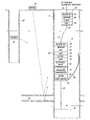
- the numeral 10 identifies the main telemetry unit. It operates in conjunction with a replicated seismic recording station generally indicated at 15 which is installed in the well borehole supported from the main unit 10.
- the string of equipment is positioned in a well supported from a logging cable 16 which is typically an armoured cable wrapped with multiple layers to provide strength and protection for one or more electrical conductors within the cable 16.
- the conductors make up the necessary data communication pathway from the main telemetry unit 10. All of this equipment is installed in a well 17 which is shown to be an open hole but which can also be a cased well. Whether open or cased, the logging cable 16 is lowered in the well until the main unit 10 is at some depth.
- the replicated recording station 15 is suspended below the main unit by a specified distance.
- the representative distance used in this disclosure is twenty-five feet (7.6m) but it will be understood that this is merely an example and that the spacing can be different.
- the number of stations can be increased until the length becomes either unwieldy or the spread of recording stations is longer than is needed.
- a typical maximum value is about twenty-five recording stations although that is arbitrary and the total number can be increased above that number.
- a seismic signal generator is identified at 18.
- the sound generators 18 or 19 can be any type of known sound generators including a tone generator, an explosive charge which is detonated to provide a shock wave or thumping devices which impact the ground. Whatever the case, they form an acoustic wave which is transmitted into the earth. It can be an impulse as occurs with an explosive charge, or it might be a fixed or variable frequency from some low to some high frequency. Devices are known which are able to sweep from just a few hertz across some audio band, e.g., from ten to two hundred hertz. By contrast with the impulse, the signal may be a continuous wave (CW) transmission.
- CW continuous wave
- Cross well surveys can use a variety of sources, and suggestions of sources include impulse or shock sources or sweep devices having frequency ranges up to a selected maximum such as one or two kilohertz. Whatever the circumstance, where are formations in the crust exemplified by the formation 21 having upper and lower interfaces with adjacent formations.
- the impulse or CW transmission of acoustic waves results in transmisson of acoustic energy into the formations and the signals are ultimately directed toward the recording station 15.
- the signals are received at the recording station 15 and are converted into electrical signals by the pressure sensors and displacement sensors in the apparatus 15. This data is converted from analog signals into digital signals, and coupled with other information such as location of the recording station at 15, the data can be analyzed and converted to provide meaningful information regarding the formation 21 and other formations in the earth.
- a surface source in a VSP routine provides small signal while crosswell transmission from the source 19 provides a larger amplitude signal at the geophone station 15.
- the path of travel as exemplified in the drawing from the sound source 18 is much longer; the path of travel is generally more direct from the sound source 19 as illustrated. Accordingly, it is necessary to use automatic gain control amplifiers, hereinafter AGC so that the signals can be handled even though they may vary from a few microvolts up to a few millivolts.
- the amplifier may also be a variable fixed gain device or perhaps an instantaneous floating point amplifier.
- the main telemetry unit 10 is provided with a suitable telemetr transmitter 24, a fairly large memory 25, a clock and CPU 26.
- the clock is provided with a trigger pulse on the logging cable 16 which initiates operation as will be described.
- the logging cable 16 terminates at the main unit.
- There is a short cable 27 which extends from the main unit 10 to the first geophone station 15. This cable 27 is again duplicated below the recording station to the next station 15 therebelow. As will be appreciated, the number can be increased. It is not necessary that the main telemetry unit 10 be fixedly clamped against the sidewall of the well.
- Station 15 It is also essential that the recording station 15 be clamped so long as displacement type listening devices are used.
- Station 15 thus includes an extended arm 28 which contacts the opposite wall and forces the recording station fixedly against the wall. This positions the recording station so that it is fixed and stationary during signal formation and transmission.
- the recording station includes a telemetry unit 30 and a memory 31.
- the memory is organized so that it can record and store data of a specified word length, and has a specified maximum storage capacity.
- a representative capacity might be anywhere from 32K to 512K words.
- a microprocessor comprising a CPU 32 is also included.
- a typical CPU can be provided by an 80188 processor.
- There is an ADC 33 which provides digitized values from analog signals.
- the ADC output can range from eight bits to perhaps sixteen bits or even eighteen or twenty bits. Additional bits associated with the digitized values include the appropriate sign bits, pity bits, error check bits and addresses in memory. Again, this can be modified depending on the memory storage space available.
- a filter 34 which is provided with an analog signal which is filtered and then applied to the ADC 33.
- An AGC amplifier 35 is also included. It provides gain at an adjustable level for amplification of the signals.
- An omnidirectional hydrophone 37 is included and it responds to pressure waves traveling through the earth.
- the numeral 38 identifies a gyro which may optionally be included to provide spatial orientation in the earth. The gyro thus provides a reference so that the structure can be oriented. It is referenced to the vertical and also north. It is a source of orientation information so that adjustments in space can be made during data reduction.
- the recording station 15, and other stations which are identical are each identified by a unique station number such as a serial number. That number is stored in the memory 25 so that a control signal can be transmitted to establish control over operation of the recording station 15.
- the CPU 26 therefore forms a control signal in accordance with a timing sequence which provides the necessary instructions for operation for the particular recording station.
- the sound source 18 is operated at a particular instant. Assume further that the recording station 15 is 10,000 feet (3050m) deep in the well and the horizon 21 of interest is 15,000 feet (4570m) in depth. A substantial interval is required for the sonic shock wave to travel from the sound source 18 to the horizon 21 for reflection to the recording station 15.
- the speed of sound through the earth is fairly well known although it might vary somewhat dependent on the nature of the formations. However, it is sufficiently well known that a delay in the equipment is permitted. Thus, while the sound may be generated at a particular instant. by actuation of the sound source 18, the recording station 15 is not switched on until time for its operation.
- an impulse may require a few seconds, perhaps eight or ten seconds for that signal to die away and become substantially nil.
- a sonic vibration generating device it might be operated for a period of ten seconds (some finite interval); this would require the recording station to be operated for at least an interval of that length although the onset will be delayed to take into account the time lag in transit from the sound source 18 to the recording station 15. This can be (in one instance) a time delay of four seconds to initiate operation of the station 15; the data should be recorded perhaps five seconds longer than the duration of the pulse from the sound source 18. In another example, it might operate for fifteen seconds. During the recording interval, the data at the sensors is sampled periodically.
- One suitable sampling rate might be 1,000 samples per second, while another sampling rate might be a total of 2,000 samples for the entire recording sequence.
- the total number of samples during operation can range anywhere from perhaps 512 to 16K or more samples. These samples are taken at regularly spaced intervals such as one sample per second, four per second, etc.
- the main unit 10 is normally deferred in operation for the necessary transit time and then it is operated to obtain n samples where n is a whole number integer and represent the number of samples, for instance, 16K samples or perhaps 512 samples, etc. Operation is therefore initiated, the N samples are thus then after a delay interval D where D is measured typically in seconds, even to an accuracy of millionths of a second.
- a prompt signal is provided from the CPU 26 at the requisite instant in time after an enable signal is provided on the conductor 16 for operation of the telemetry equipment. Operation is started in the recording station 15, and the sonic signal is received by the three displacement transducers and one pressure transducer and then an analog signal input to the amplifier 35. Recalling that the input signals can vary widely from just a few microvolts, the four analog signals are output to the variable gain amp 35, and the signals are amplified by specified gain.
- the four signals are preferably handled on a multiplexed sequence.
- the four signals can be provided to four dedicated ADC circuits for data conversion.
- the four analog signals are in sequence amplified by a specified level of gain where the gain is indicated by the AGC setting from the amplifier 35, the signals are then filtered by the filter 34 to remove frequency content above a certain frequency level, and the signal is then converted into digital form by the ADC 33. That data is stored as a particular word after transmission from the ADC into the CPU 32 and then to the memory 31.
- the entry comprising the data word is made up of several data which include the gain level setting, the sign, the measured variable, appropriate parity and error check bits, and other data as necessary to convey the value of this variable.
- these words are written in a particular sequence from the CPU 32 into the memory 31 and are stored in a particular sequence in the memory.
- a fixed protocol is established.
- the protocol can be exemplified by first providing the fixed data as a set of initial conditions. Items preferably included in the fixed or initial data which is stored prior to measured variable data includes at least the following.
- One item of fixed data is a signal from the arm control 39 which states that the arm has been fully extended, locked in position and that the recording station 15 is firmly held in place.
- the gyro 38 provides data indicating the position in space of the recording station, typically represented as the three resolved components of position such as angle with respect to vertical, angle with respect to a north-south axis, and angle with respect to an east-west axis. This can have the form of three numbers which identify the orientation is space.
- Another element of fixed data is the initial setting of the amplifier 35.
- Another element of fixed data is the serial number identifying the recording station 15 in particular so that the device and its data can be coordinated.
- the four analog signals are then sampled. These values are provided from the respective analog transducers to the amplifier 35 and are filtered by the filter 34 and converted into digital values by an ADC 33. Assume, for purposes of discussion, that the samples occur at a rate to total 8,000 samples. In each sample, assume that it is helpful to obtain an indication of the analog value.
- the displacement sensors are organized on an XYZ system so that the variables from the three sensors are represented as x, x 2 , ... Xn where n equals the number of samples obtained in the specified interval B.
- the signal from the pressure is h i ... h n .
- the sequence of data delivered for storage in the memory might well be h 1 , X1 , Y1 , Z1 and is repeated for h 2 , ... etc.
- the data can be stored in an interlaced fashion; however, storage without interlacing has an advantage, namely, that one source only can be retrieved from memory quickly. If only the pressure data is desired, it can be retrieved easily by interrogating its assigned block of memory.
- Each analog signal is converted into digital form and they are then delivered to the memory 31 for storage in a particular storage sequence. It is not necessary to repeat the fixed information except once for each set of samples obtained from the input analog signals.
- the fixed data is determined only once and is stored in the memory 31 while the sampled data is sampled over the n samples where n typically is in the range of about 512 to about 16K samples. It will be understood that the variables are the signals of h, x, y and z.
- the present system is installed where there are multiple recording stations 15.
- M the number of stations, and of course this requires that M be a whole number positive integer.
- the spacing between the various stations M from the main telemetry unit 10 is quite close. If the cable 27 is only twenty-five feet (7.6m) in length and that is replicated for the various recording stations 15, then the total span of cable below the unit 10 is only 25 times M feet (1 foot is 0.30m). Twenty-five stations would represent a spread of 625 feet (191 m) in total cable lengh with the closest being only twenty-five feet (7.6m) below the unit 10. This short travel distance eases the telemetry requisements from the most remote of the recording stations 15 to the unit 10.
- transmission over 1,000 feet (305m) permits a transmission rate at a specified high data transfer rate.
- the data transfer rate from the station 15 to the main unit 10 might readily be perhaps 256 words per second, or even more. Data transfer rates over one million bits per second or higher contemplated, again depending on word length which in turn is dependent on the precision of the ADC 33 and the number of companion bits completing a single word. This data is thus transferred from a particular station 15 afterthe set of data points n has been recorded in the memory 31.
- the CPU 26 When the CPU 26 provides a prompt signal on the conductor 27 to the geophone station 15, the 8,192 words are then transferred from the memory 31 through the cable 27, are formatted by the CPU 26, and assigned to a specified memory location in the memory 25 for storage in a desired sequence. This is done in a sequence controlled by the CPU 26 for all of the M recording stations 15 and so they in turn transmit the data for collection and storage in the memory 25.
- the memory 25 must be sufficiently large to store this amount of data from M stations 15.
- an impulse shock wave 18 is provided and the impulse shock wave is repeated approximately twenty seconds later.
- the first set of data from the first impulse is recorded over a period of time (e,g., eight seconds) while the data is being created and is stored in the memories 31 of the M stations 15.
- the M stations can be cleared of data in the several memories 31 so that all that data is written in the memory 25 to leave the memory units 31 cleared of data.
- the memories 31 can be used to dynamically receive the next transaction, i.e., the following impulse from the sound source 18 and the resultant seismic waves transmitted through the formations to the M stations 15.
- the data transfer rate on the short cable 27 is quite rapid in comparison with the permitted data transfer rate up the cable 16. Perhaps some representative values will make this more clear.
- the transfer rate over the cable 27 even where the span of M stations is as much as 1,000 feet (305m) in length can approach about 10 megabits/second. That rate can be safely and routinely accommodated with substantially error free transmission.
- the data transfer rate on the cable 16 is constrained by the substantial length of the cable 16.
- the cable 16 can readily be as long as 25,000 feet (7620m) in length to accommodate wells of great depth with substantial cable spooled on the supply drum or reel. This length limits the data transfer rate perhaps to 100K bps. This is the transfer rate assuming a single conductor pair.
- the data transfer rate might be increased, perhaps to greater than 256K bps.
- the CPU 26 thus prompts the memory 25 to deliver data from the memory 25 through the telemetry 24 on receiving a hand shake signal from the surface telemetry receiver indicating that it is ready.
- the transfer of data can be initiated at any point in time up the cable 16 so that data is delivered from the memory 25 independent of the transactions going on at the memories 31 in the respective recording stations 15.
- B 1 represent the batch of data from the memory 25 which derives from the first sonic transmission from the sound sources 18 or 19, and B 2 represents the second batch of data.
- the sound sources 18 or 19 may be operated only once or may be operated many times so that the total record is comprised of the routess B 1' B 2 , ... B k where k is a positive integer and represents the total number of cycles of operation of the sound sources.
- Stacking is a technique sometimes used to improve the quality of the data. Assume that the recording station 15 is held at a specific location and that a sonic impulse from an explosive is transmitted from the sound source 18. That is recorded for an interval of T seconds to assure recording of the onset, and trailing end of the signal. Typically, T is relatively short, and can be just a few seconds, typically not more than about twenty seconds. As previously mentioned, the interval of T seconds is divided by n where evenly spaced samples are taken, and the number of samples is represented by n as previously mentioned. In any event, stacking is accomplished by positioning the recording station 15 at a specified depth, operating the sound impulse device 18 and forming a first operating the sound impulse device 18 and forming a first record B 1 at the M recording stations 15.
- This data was defined as the data batch B 1 .
- the foregoing is repeated without moving the sound source 18 and without moving the station 15. This is repeated until K equals perhaps four, nine or sixteen.
- the signals B 1 to B k are summed and an average is taken. More specifically, the signals average reduces the relative significance of randomly occurring noise and otherwise provides reenforcement of coherent aspects of the received signals.
- the sound source is moved in a region defining a circle of perhaps 50 feet (15.2m) diameter while mapping the formation at a depth of 15,000 feet (4570m), and where the recording station 15 is 10,000 feet (3050m) deep in the well 17, such seismic source relocation does not materially change the angle of incidence of the radiated seismic wave directed to the horizon 21.
- the data transfer rates given above are examples of data transfer rates, and are not necessarily limitations on the transfer rate. This system does, however, the advantage of the fact that the data transfer rate up the cable 27 can ordinaly be much faster because the distance is quite short in comparison with the logging cable 16. In the latter instance, the transfer rate is normally much slower because precautions must be taken to assure clarity of reception at the surface.
- the memory 25 can be built sufficiently large that it holds several batches such as b 1 ... b k so that k repeated cycles of operation of the sound device 18 permits all this data to be stored in memory without partial transfer to the surface.
- the data can be reduced at the surface by applying several procedures. For instance, the foregoing described stacking so that the sound source 18 is operated for up to K times and the signals are then stacked. That is, for the K signals from the X sensor, the signals X1 , X2 ... Xn are thus recorded and averaged with the repeated recordings until the K recordings have been stacked for the X sensor and also the Y and Z sensors. Prior to stacking, it may be desirable to provide relative rotation between sensors.
- the data from the three sensors can be trigonometrically converted so that all sensors are brought to a common axis such as a reference vertical axis, north-south and also east-west axis. The three axis rotation of the sensor data is believed to be a known procedure. Data can be reduced by the use of various data compression components or data compression algorithms.
- the sound source 19 is used in the same fashion as the sound source 18. Because of the differences in geometry, there are some differences in the source 19 impinges along a more direct path and therefore is normally a larger signal. It can measure in the hundreds of microvolts. By contrast, the signal from the sensors resulting from the sound source 18 can readily be in the microvolt range and require substantially more amplification by the amplifier 35. The differences in signal levels are ordinarily accommodated by changes in the gain setting of the amplifier 35.
- Variations in the present equipment are generally accommodations of scale.
- the number of recording stations 15 can be varied as M is increased or reduced, and the spacing from station to station, while normally uniform, can be varied also.
- the data transfer rates on the cable 27 and 16 are likewise different maximum transfer rates so that the transmission rate on the cable 16 may well require overlapping operation of the telemetry 24 with the several telemetry units 30 in the M stations 15.
- the mechanical structure may have multiple mechanical resonant frequencies scattered above about 100 hertz.
- several smaller mechanical structures which are coupled by cables are simpler in design, smaller, and hence, have much higher resonant frequencies.
- the resonant frequency can be as high as several hundred hertz, perhaps 1000 hertz which markedly enhances the frequency band that can be received without resonating.
Landscapes
- Physics & Mathematics (AREA)
- Life Sciences & Earth Sciences (AREA)
- Engineering & Computer Science (AREA)
- Acoustics & Sound (AREA)
- Environmental & Geological Engineering (AREA)
- Geology (AREA)
- Remote Sensing (AREA)
- General Life Sciences & Earth Sciences (AREA)
- General Physics & Mathematics (AREA)
- Geophysics (AREA)
- Geophysics And Detection Of Objects (AREA)
Applications Claiming Priority (2)
| Application Number | Priority Date | Filing Date | Title |
|---|---|---|---|
| US07/590,843 US5157392A (en) | 1990-10-01 | 1990-10-01 | Telemetry network for downhole multistation seismic recording tools |
| US590843 | 1996-01-24 |
Publications (2)
| Publication Number | Publication Date |
|---|---|
| EP0479543A2 true EP0479543A2 (de) | 1992-04-08 |
| EP0479543A3 EP0479543A3 (en) | 1993-05-12 |
Family
ID=24363953
Family Applications (1)
| Application Number | Title | Priority Date | Filing Date |
|---|---|---|---|
| EP19910308959 Withdrawn EP0479543A3 (en) | 1990-10-01 | 1991-09-30 | Obtaining seismic data from well borehole |
Country Status (5)
| Country | Link |
|---|---|
| US (1) | US5157392A (de) |
| EP (1) | EP0479543A3 (de) |
| BR (1) | BR9104233A (de) |
| CA (1) | CA2052479A1 (de) |
| MX (1) | MX9101388A (de) |
Cited By (4)
| Publication number | Priority date | Publication date | Assignee | Title |
|---|---|---|---|---|
| GB2290869A (en) * | 1994-06-28 | 1996-01-10 | Western Atlas Int Inc | Slickline conveyed wellbore seismic receiver |
| US5585556A (en) * | 1994-12-05 | 1996-12-17 | Norsk Hydro A.S. | Method and apparatus for performing measurements while drilling for oil and gas |
| WO1998012577A1 (en) * | 1996-09-20 | 1998-03-26 | Geco-Prakla (Uk) Limited | Seismic sensor units |
| WO2002025317A1 (en) * | 2000-09-22 | 2002-03-28 | Services Petroliers Schlumberger | Methods, systems and tools for borehole logging |
Families Citing this family (17)
| Publication number | Priority date | Publication date | Assignee | Title |
|---|---|---|---|---|
| GB2312063B (en) * | 1996-04-09 | 1998-12-30 | Anadrill Int Sa | Signal recognition system for wellbore telemetry |
| US6703838B2 (en) * | 1998-04-13 | 2004-03-09 | Schlumberger Technology Corporation | Method and apparatus for measuring characteristics of geological formations |
| US6294917B1 (en) | 1999-09-13 | 2001-09-25 | Electromagnetic Instruments, Inc. | Electromagnetic induction method and apparatus for the measurement of the electrical resistivity of geologic formations surrounding boreholes cased with a conductive liner |
| US6308137B1 (en) * | 1999-10-29 | 2001-10-23 | Schlumberger Technology Corporation | Method and apparatus for communication with a downhole tool |
| US6885918B2 (en) * | 2000-06-15 | 2005-04-26 | Geo-X Systems, Ltd. | Seismic monitoring and control method |
| US6977867B2 (en) * | 2001-06-05 | 2005-12-20 | Geo-X Systems, Ltd. | Seismic data acquisition system |
| US6957147B2 (en) * | 2002-03-12 | 2005-10-18 | Sercel, Inc. | Data management for seismic acquisition using variable compression ratio as a function of background noise |
| US7139218B2 (en) * | 2003-08-13 | 2006-11-21 | Intelliserv, Inc. | Distributed downhole drilling network |
| CA2485761C (en) * | 2003-10-24 | 2015-11-24 | Bernd Milkereit | Resonance scattering seismic method |
| US20060081412A1 (en) * | 2004-03-16 | 2006-04-20 | Pinnacle Technologies, Inc. | System and method for combined microseismic and tiltmeter analysis |
| US20060013065A1 (en) * | 2004-07-16 | 2006-01-19 | Sensorwise, Inc. | Seismic Data Acquisition System and Method for Downhole Use |
| US7453768B2 (en) * | 2004-09-01 | 2008-11-18 | Hall David R | High-speed, downhole, cross well measurement system |
| US20060067162A1 (en) * | 2004-09-29 | 2006-03-30 | Blankinship Thomas J | Ultrasonic cement scanner |
| US8951190B2 (en) * | 2005-09-28 | 2015-02-10 | Zin Technologies, Inc. | Transfer function control for biometric monitoring system |
| US7969819B2 (en) * | 2006-05-09 | 2011-06-28 | Schlumberger Technology Corporation | Method for taking time-synchronized seismic measurements |
| US8401796B2 (en) * | 2008-09-29 | 2013-03-19 | Schlumberger Technology Corporation | Methods and systems for acoustically monitoring formations |
| US9784097B2 (en) | 2015-03-30 | 2017-10-10 | Baker Hughes Incorporated | Compressed telemetry for time series downhole data using variable scaling and grouped words |
Family Cites Families (14)
| Publication number | Priority date | Publication date | Assignee | Title |
|---|---|---|---|---|
| US3315224A (en) * | 1964-09-01 | 1967-04-18 | Exxon Production Research Co | Remote control system for borehole logging devices |
| US4216536A (en) * | 1978-10-10 | 1980-08-05 | Exploration Logging, Inc. | Transmitting well logging data |
| US4718011A (en) * | 1982-11-01 | 1988-01-05 | Western Atlas International, Inc. | Well logging data acquisition, telemetry and control method and system |
| US4684947A (en) * | 1983-09-08 | 1987-08-04 | Halliburton Company | Simultaneous digitizing apparatus for an acoustic tool |
| AU3269184A (en) * | 1983-09-08 | 1985-03-14 | Halliburton Company | Simultaneous digitizing of all receivers in acoustic tool |
| FR2561394B1 (fr) * | 1984-02-28 | 1987-03-20 | Inst Francais Du Petrole | Dispositif de reception d'ondes acoustiques dans un puits |
| WO1988004131A2 (en) * | 1986-11-19 | 1988-06-16 | The Commonwealth Of Australia | Distributed array hydrophone |
| FR2613496B1 (fr) * | 1987-04-02 | 1989-07-21 | Inst Francais Du Petrole | Dispositif pour l'acquisition de donnees sismiques dans un forage et leur transmission a un systeme central de commande et d'enregistrement |
| US4800981A (en) * | 1987-09-11 | 1989-01-31 | Gyrodata, Inc. | Stabilized reference geophone system for use in downhole environment |
| US4897646A (en) * | 1988-12-29 | 1990-01-30 | Atlantic Richfield Company | Method and apparatus for reducing the effective bandwidth of ultrasonic waveform for transmission over a logging cable |
| GB2230091A (en) * | 1989-03-23 | 1990-10-10 | Roy Baria | A two-module seismic borehole logging sonde |
| US5010333A (en) * | 1989-05-17 | 1991-04-23 | Halliburton Logging Services, Inc. | Advanced digital telemetry system for monocable transmission featuring multilevel correlative coding and adaptive transversal filter equalizer |
| FR2656110B1 (fr) * | 1989-12-19 | 1992-05-07 | Inst Francais Du Petrole | Source sismique vibrante utilisable notamment dans des puits. |
| US4999817A (en) * | 1990-02-22 | 1991-03-12 | Halliburton Logging Services, Inc. | Programmable gain control for rotating transducer ultrasonic tools |
-
1990
- 1990-10-01 US US07/590,843 patent/US5157392A/en not_active Expired - Lifetime
-
1991
- 1991-09-30 CA CA002052479A patent/CA2052479A1/en not_active Abandoned
- 1991-09-30 EP EP19910308959 patent/EP0479543A3/en not_active Withdrawn
- 1991-10-01 BR BR919104233A patent/BR9104233A/pt not_active Application Discontinuation
- 1991-10-01 MX MX9101388A patent/MX9101388A/es unknown
Cited By (12)
| Publication number | Priority date | Publication date | Assignee | Title |
|---|---|---|---|---|
| GB2290869A (en) * | 1994-06-28 | 1996-01-10 | Western Atlas Int Inc | Slickline conveyed wellbore seismic receiver |
| GB2290869B (en) * | 1994-06-28 | 1998-07-15 | Western Atlas Int Inc | Slickline conveyed wellbore seismic receiver |
| NL1000683C2 (nl) * | 1994-06-28 | 1998-11-03 | Western Atlas Int | Inrichting voor het registreren van een geofysisch onderzoek in een boorput. |
| US5585556A (en) * | 1994-12-05 | 1996-12-17 | Norsk Hydro A.S. | Method and apparatus for performing measurements while drilling for oil and gas |
| EP0716319A3 (de) * | 1994-12-05 | 1997-05-28 | Norsk Hydro As | Verfahren und Anordnung zur Messung während des Bohrens für Öl und Gaz |
| WO1998012577A1 (en) * | 1996-09-20 | 1998-03-26 | Geco-Prakla (Uk) Limited | Seismic sensor units |
| GB2332275A (en) * | 1996-09-20 | 1999-06-16 | Schlumberger Holdings | Seismic sensor units |
| GB2332275B (en) * | 1996-09-20 | 2001-02-14 | Schlumberger Holdings | Seismic sensor units |
| WO2002025317A1 (en) * | 2000-09-22 | 2002-03-28 | Services Petroliers Schlumberger | Methods, systems and tools for borehole logging |
| GB2382653A (en) * | 2000-09-22 | 2003-06-04 | Schlumberger Holdings | Methods, systems and tools for borehole logging |
| US6630890B1 (en) | 2000-09-22 | 2003-10-07 | Schlumberger Technology Corporation | Methods, systems and tools for borehole logging |
| GB2382653B (en) * | 2000-09-22 | 2004-11-03 | Schlumberger Holdings | Methods, systems and tools for borehole logging |
Also Published As
| Publication number | Publication date |
|---|---|
| MX9101388A (es) | 1992-06-05 |
| EP0479543A3 (en) | 1993-05-12 |
| BR9104233A (pt) | 1992-06-02 |
| CA2052479A1 (en) | 1992-04-02 |
| US5157392A (en) | 1992-10-20 |
Similar Documents
| Publication | Publication Date | Title |
|---|---|---|
| US5157392A (en) | Telemetry network for downhole multistation seismic recording tools | |
| US4807200A (en) | Method and apparatus for gathering seismic data and selectively controlling isolated distributed recorders in an isolated distributed recording system | |
| US5790473A (en) | High fidelity vibratory source seismic method for use in vertical seismic profile data gathering with a plurality of vibratory seismic energy sources | |
| US5555220A (en) | Slickline conveyed wellbore seismic receiver | |
| US4493063A (en) | Method and apparatus for seismic geophysical exploration | |
| US8902700B2 (en) | Borehole seismic acquisition system | |
| US7668047B2 (en) | Method for correcting seismic data timing functions utilizing orientation data | |
| US6568486B1 (en) | Multipole acoustic logging with azimuthal spatial transform filtering | |
| Hedlin et al. | The time-frequency characteristics of quarry blasts and calibration explosions recorded in Kazakhstan, USSR | |
| JPS62162987A (ja) | 適応型地震計グル−プ記録装置 | |
| US7388811B2 (en) | Method for separating microseismic signals from seismic signals emitted by one or several sources | |
| US6181642B1 (en) | Apparatus and method for borehole seismic exploration | |
| US4302825A (en) | Rotating eccentric weight apparatus and method for generating coded shear wave signals | |
| US11016213B2 (en) | Gradient-based 4D seabed acquisition positioning | |
| US5042611A (en) | Method and apparatus for cross-well seismic surveying | |
| CN112083475A (zh) | 地震数据采集系统的地震数据采集方法 | |
| US5005666A (en) | Attenuation of borehole tube-waves | |
| US11898901B2 (en) | Method and system for mapping fiber optic distributed acoustic sensing measurements to particle motion | |
| GB2533479A (en) | Downhole acoustic wave sensing with optical fiber | |
| US4879696A (en) | Method and apparatus for initiating seismic data storage in an isolated distributed recording system | |
| US4327814A (en) | Rotating eccentric weight apparatus and method for generating coded shear wave signals | |
| JPS59136671A (ja) | 現場における地震デ−タ処理能力を有する無線式デイジタル地震記録装置 | |
| US10072497B2 (en) | Downhole acoustic wave sensing with optical fiber | |
| US3760347A (en) | High resolution reflection shooting | |
| GB2318185A (en) | Borehole seismic exploration |
Legal Events
| Date | Code | Title | Description |
|---|---|---|---|
| PUAI | Public reference made under article 153(3) epc to a published international application that has entered the european phase |
Free format text: ORIGINAL CODE: 0009012 |
|
| AK | Designated contracting states |
Kind code of ref document: A2 Designated state(s): DE FR GB NL |
|
| PUAL | Search report despatched |
Free format text: ORIGINAL CODE: 0009013 |
|
| AK | Designated contracting states |
Kind code of ref document: A3 Designated state(s): DE FR GB NL |
|
| STAA | Information on the status of an ep patent application or granted ep patent |
Free format text: STATUS: THE APPLICATION IS DEEMED TO BE WITHDRAWN |
|
| 18D | Application deemed to be withdrawn |
Effective date: 19931113 |