EP0478968A2 - Servo controller for a forward/reverse mechanism - Google Patents
Servo controller for a forward/reverse mechanism Download PDFInfo
- Publication number
- EP0478968A2 EP0478968A2 EP91114816A EP91114816A EP0478968A2 EP 0478968 A2 EP0478968 A2 EP 0478968A2 EP 91114816 A EP91114816 A EP 91114816A EP 91114816 A EP91114816 A EP 91114816A EP 0478968 A2 EP0478968 A2 EP 0478968A2
- Authority
- EP
- European Patent Office
- Prior art keywords
- fluid
- piston
- reverse
- chamber
- pressure
- Prior art date
- Legal status (The legal status is an assumption and is not a legal conclusion. Google has not performed a legal analysis and makes no representation as to the accuracy of the status listed.)
- Withdrawn
Links
- 230000007246 mechanism Effects 0.000 title claims description 8
- 239000012530 fluid Substances 0.000 claims abstract description 67
- 230000005540 biological transmission Effects 0.000 claims abstract description 27
- 238000004891 communication Methods 0.000 claims abstract description 10
- 238000000034 method Methods 0.000 description 3
- 230000007935 neutral effect Effects 0.000 description 2
- 238000007789 sealing Methods 0.000 description 2
- 230000006835 compression Effects 0.000 description 1
- 238000007906 compression Methods 0.000 description 1
- 230000007423 decrease Effects 0.000 description 1
- 238000010586 diagram Methods 0.000 description 1
- 238000006073 displacement reaction Methods 0.000 description 1
- 230000009977 dual effect Effects 0.000 description 1
- 238000011156 evaluation Methods 0.000 description 1
- 230000035939 shock Effects 0.000 description 1
Images


Classifications
-
- F—MECHANICAL ENGINEERING; LIGHTING; HEATING; WEAPONS; BLASTING
- F16—ENGINEERING ELEMENTS AND UNITS; GENERAL MEASURES FOR PRODUCING AND MAINTAINING EFFECTIVE FUNCTIONING OF MACHINES OR INSTALLATIONS; THERMAL INSULATION IN GENERAL
- F16D—COUPLINGS FOR TRANSMITTING ROTATION; CLUTCHES; BRAKES
- F16D67/00—Combinations of couplings and brakes; Combinations of clutches and brakes
-
- F—MECHANICAL ENGINEERING; LIGHTING; HEATING; WEAPONS; BLASTING
- F16—ENGINEERING ELEMENTS AND UNITS; GENERAL MEASURES FOR PRODUCING AND MAINTAINING EFFECTIVE FUNCTIONING OF MACHINES OR INSTALLATIONS; THERMAL INSULATION IN GENERAL
- F16H—GEARING
- F16H63/00—Control outputs from the control unit to change-speed- or reversing-gearings for conveying rotary motion or to other devices than the final output mechanism
- F16H63/02—Final output mechanisms therefor; Actuating means for the final output mechanisms
- F16H63/30—Constructional features of the final output mechanisms
- F16H63/3023—Constructional features of the final output mechanisms the final output mechanisms comprising elements moved by fluid pressure
-
- F—MECHANICAL ENGINEERING; LIGHTING; HEATING; WEAPONS; BLASTING
- F16—ENGINEERING ELEMENTS AND UNITS; GENERAL MEASURES FOR PRODUCING AND MAINTAINING EFFECTIVE FUNCTIONING OF MACHINES OR INSTALLATIONS; THERMAL INSULATION IN GENERAL
- F16H—GEARING
- F16H61/00—Control functions within control units of change-speed- or reversing-gearings for conveying rotary motion ; Control of exclusively fluid gearing, friction gearing, gearings with endless flexible members or other particular types of gearing
- F16H61/02—Control functions within control units of change-speed- or reversing-gearings for conveying rotary motion ; Control of exclusively fluid gearing, friction gearing, gearings with endless flexible members or other particular types of gearing characterised by the signals used
- F16H61/0202—Control functions within control units of change-speed- or reversing-gearings for conveying rotary motion ; Control of exclusively fluid gearing, friction gearing, gearings with endless flexible members or other particular types of gearing characterised by the signals used the signals being electric
- F16H61/0204—Control functions within control units of change-speed- or reversing-gearings for conveying rotary motion ; Control of exclusively fluid gearing, friction gearing, gearings with endless flexible members or other particular types of gearing characterised by the signals used the signals being electric for gearshift control, e.g. control functions for performing shifting or generation of shift signal
- F16H61/0246—Control functions within control units of change-speed- or reversing-gearings for conveying rotary motion ; Control of exclusively fluid gearing, friction gearing, gearings with endless flexible members or other particular types of gearing characterised by the signals used the signals being electric for gearshift control, e.g. control functions for performing shifting or generation of shift signal characterised by initiating reverse gearshift
-
- F—MECHANICAL ENGINEERING; LIGHTING; HEATING; WEAPONS; BLASTING
- F16—ENGINEERING ELEMENTS AND UNITS; GENERAL MEASURES FOR PRODUCING AND MAINTAINING EFFECTIVE FUNCTIONING OF MACHINES OR INSTALLATIONS; THERMAL INSULATION IN GENERAL
- F16H—GEARING
- F16H61/00—Control functions within control units of change-speed- or reversing-gearings for conveying rotary motion ; Control of exclusively fluid gearing, friction gearing, gearings with endless flexible members or other particular types of gearing
- F16H61/02—Control functions within control units of change-speed- or reversing-gearings for conveying rotary motion ; Control of exclusively fluid gearing, friction gearing, gearings with endless flexible members or other particular types of gearing characterised by the signals used
- F16H61/0202—Control functions within control units of change-speed- or reversing-gearings for conveying rotary motion ; Control of exclusively fluid gearing, friction gearing, gearings with endless flexible members or other particular types of gearing characterised by the signals used the signals being electric
- F16H61/0251—Elements specially adapted for electric control units, e.g. valves for converting electrical signals to fluid signals
- F16H2061/0255—Solenoid valve using PWM or duty-cycle control
-
- F—MECHANICAL ENGINEERING; LIGHTING; HEATING; WEAPONS; BLASTING
- F16—ENGINEERING ELEMENTS AND UNITS; GENERAL MEASURES FOR PRODUCING AND MAINTAINING EFFECTIVE FUNCTIONING OF MACHINES OR INSTALLATIONS; THERMAL INSULATION IN GENERAL
- F16H—GEARING
- F16H61/00—Control functions within control units of change-speed- or reversing-gearings for conveying rotary motion ; Control of exclusively fluid gearing, friction gearing, gearings with endless flexible members or other particular types of gearing
- F16H61/68—Control functions within control units of change-speed- or reversing-gearings for conveying rotary motion ; Control of exclusively fluid gearing, friction gearing, gearings with endless flexible members or other particular types of gearing specially adapted for stepped gearings
- F16H61/682—Control functions within control units of change-speed- or reversing-gearings for conveying rotary motion ; Control of exclusively fluid gearing, friction gearing, gearings with endless flexible members or other particular types of gearing specially adapted for stepped gearings with interruption of drive
-
- Y—GENERAL TAGGING OF NEW TECHNOLOGICAL DEVELOPMENTS; GENERAL TAGGING OF CROSS-SECTIONAL TECHNOLOGIES SPANNING OVER SEVERAL SECTIONS OF THE IPC; TECHNICAL SUBJECTS COVERED BY FORMER USPC CROSS-REFERENCE ART COLLECTIONS [XRACs] AND DIGESTS
- Y10—TECHNICAL SUBJECTS COVERED BY FORMER USPC
- Y10T—TECHNICAL SUBJECTS COVERED BY FORMER US CLASSIFICATION
- Y10T74/00—Machine element or mechanism
- Y10T74/19—Gearing
- Y10T74/19219—Interchangeably locked
- Y10T74/19377—Slidable keys or clutches
- Y10T74/19414—Single clutch shaft
- Y10T74/19484—Single speed forward and reverse
- Y10T74/19488—Spur gears
Definitions
- This invention relates to servo mechanisms, and more particularly, to servo mechanisms for controlling the shifting of a transmission between a forward ratio and a reverse ratio.
- a forward/reverse servo controller in accordance with the present invention is characterised by the features specified in the characterising portion of claim 1.
- the present invention provides a control system and a mechanical forward/reverse clutch mechanism which ensures that a minimum speed differential, between a reverse gear member and a transmission shaft, is present prior to engaging the mechanical clutch between the transmission shaft and the reverse gear member.
- a shift control structure includes a servo member operatively connected with a portion of the mechanical clutch to provide for the shifting of the clutch.
- the servo includes a piston which cooperates with a housing to provide two fluid chambers which are selectively disposed for controlled fluid communication.
- the chambers are disconnected and in the reverse select position, the chambers are interconnected.
- the servo is urged to the forward select position by a spring which has sufficient precompression to resist the movement of the piston to the reverse select position prior to the fluid pressure in one of the chambers being increased above a desired threshold level.
- the fluid pressure which is supplied to the chamber is preferably provided by an electro-hydraulic control system which includes a microprocessor and a line pressure regulator.
- the microprocessor evaluates various vehicle parameters including engine speed, engine torque and vehicle speed. These parameters are evaluated by the microprocessor in a manner to establish a voltage signal to a pulse-width-modulated solenoid valve which controls the line pressure for the transmission hydraulic components in accordance with the duty cycle of the signal.
- the line pressure will not be sufficient to cause the piston to move against the spring. Accordingly, a forward/reverse shift will not occur and, as a general rule, the transmission will be placed in neutral by exhausting the various friction clutches.
- the microprocessor continuously monitors the operating parameters and the operating requests, such that when the vehicle speed, for example, has been reduced below a threshold value, the line pressure will be increased sufficiently to cause the servo piston to move to the reverse select position and therefore selectively clutch the transmission shaft to the reverse gear.
- the two chambers are fluidly interconnected and a fluid pressure in the second chamber is directed to a friction clutch and a control valve to establish or otherwise enforce the engagement of the friction clutch which will condition the transmission for reverse drive operation.
- a forward/reverse servo controller hereinafter referred to as servo 10, generally designated 10, which includes a casing or housing 12, an end cover 14, a piston 16 and a compression spring 18.
- the piston 16 is slidably disposed in the housing 12 and is urged rightward to the position shown in Figure 1 by the spring 18 which is compressed between the housing 12 and the end cover 14.
- the piston 16 has three circumferentially extending surfaces 20, 22 and 24.
- Circumferential surface 20 is slidably sealingly engaged in a bore 26 formed in the housing 12 and forms the outer surface for a piston rod 28, which has secured thereto a shift fork 30 by means of a threaded fastener 32.
- the circumferential surface 22 sealingly engages a surface 34 formed on the housing 12 and cooperates therewith to define a first fluid chamber 36.
- the circumferential surface 24 has disposed thereon a seal member 38 which cooperates with a surface 40 formed on the housing 12 to define a second fluid chamber 42 and a third fluid chamber 44.
- the second fluid chamber 42 is formed on the same side of the piston 16 as the first fluid chamber 36 and the third fluid chamber 44 is disposed on the opposite side of the piston 16.
- the circumferential surface 22 is in fluid communication with a radial passage 46, an axial passage 48 and another radial passage 50.
- the radial passage 50 is open to exhaust in the position shown in Figure 1, which thereby exhausts the fluid pressure in the second fluid chamber 42.
- the radial passage 50 is sealed by the sealing engagement between the circumferential surface 20 and bore 26.
- the radial passage 50 is disposed to be closed from atmosphere when the circumferential surface 22 is moved out of sealing engagement with the surface 34.
- the shift fork 30 is operatively connected to an annular clutch sleeve 52 which has a splined inner diameter 54.
- the splined inner diameter 54 is adapted to mesh continuously with a splined outer diameter 56 of a clutch hub 58, which in turn, is drivingly connected through a splined connection 60 with a transmission shaft 62.
- the splined inner diameter 54 of clutch sleeve 52 is also selectively engageable with a spline 64 formed on a forward gear 66, as seen in Figure 1, and with a spline 68 formed on a reverse gear 70, as seen in Figure 2.
- the forward and reverse gears 66 and 70 respectively are rotatably supported on the transmission shaft 62 by bearing members 72 and 74, respectively.
- the forward gear 66 is drivingly connected with the transmission shaft 62 when the servo 10 is in the forward select position shown in Figure 1. It should also be obvious that in this position, the reverse gear 70 is freely rotatable on the transmission shaft 62. It should likewise be apparent that when the servo 10 is moved to the reverse select position shown in Figure 2, that the reverse gear 70 is drivingly connected to the transmission shaft 62 while the forward gear 66 is freely rotatable on the transmission shaft 62.
- the forward and reverse gears 66 and 70 respectively, and clutch hub 58 are controlled to their axial positions on the transmission shaft 62 by a pair of thrust bearings 76 and 78 which are disposed between a sleeve shaft 80 and bearing 82, respectively.
- the first fluid chamber 36 is in fluid communication with a reverse shift signal passage 84 which receives a selective signal from a conventional shift controller 86.
- the second fluid chamber 42 is in fluid communication with a clutch fill passage 88 which is in fluid communication through a one-way or check valve 90 with a clutch valve passage 92.
- the clutch valve passage 92 is selectively pressurizable to control the engagement of a conventional, fluid operated, friction clutch 94.
- the fluid pressure in the friction clutch 94 is controlled by a conventional pulse-width-modulator type solenoid valve 96 (PWM).
- PWM pulse-width-modulator type solenoid valve 96
- the check valve 90 will prevent fluid flow from the clutch valve passage 92 to exhaust through the passages in the piston rod 28 when the forward select position is established.
- the friction clutch 94 can also be used for a forward ratio.
- the third fluid chamber 44 is in fluid communicatoin with a pressure passage 98 which is pressurized by the shift controller 86 and at least the first or lowest forward speed transmission operation.
- the shift controller 86 receives fluid pressure from a line pressure regulator valve 100 which is supplied by a conventional positive displacement pump 102.
- the line pressure regulator valve 100 is a conventional valve which is controlled by a conventional pulse-width-modulated solenoid valve 104 (PWM) to establish a controlled pressure level in a passage 106 which is connected with the shift controller 86.
- PWM pulse-width-modulated solenoid valve
- the pulse-width-modulated solenoid valves 96 and 104 are controlled by a conventional microprocessor or digital computer 108.
- the microprocessor 108 is effective to receive input signals, such as vehicle speed 110, engine speed 112, engine torque 114 and operating temperature 116. Obviously, other vehicle parameters can be input to the microprocessor 108 depending upon the program which is to be executed by the microprocessor 108.
- the microprocessor 108 is effective to provide output signals, in accordance with its programming, and input signals which can be utilized to control the pulse-width-modulated solenoid valves 104 and 96, as well as shift control functions, which are represented by a variety of output signals 118.
- the microprocessor 108 is effective to control the line pressure regulator valve 100 to establish at least two distinct pressure levels in the passage 106 and therefore in the reverse shift signal passage 84.
- the pressure level in passage 84 can be controlled at a low level, for example, 450 kpa, and at a high level, for example, 900 kpa.
- the fluid pressure in fluid chamber 36 is not sufficient to overcome the precompression force in spring 18 and therefore servo 10 will remain in the forward select position shown in Figure 1.
- the pressure level in reverse shift signal passage 84 is at the higher level, the fluid pressure in the fluid chamber 36 is sufficient to cause movement of the servo 10 from the forward select position of Figure 1 to the reverse position of Figure 2.
- the fluid in fluid chamber 36 is connected to the fluid in chamber 42 and via clutch fill and clutch valve passages 88 and 92, to the friction clutch 94.
- the friction clutch 94 will in turn be selectively engaged at a pressure level established by the pulse-width-modulated solenoid valve 96.
- the fluid pressure in reverse shift signal passage 84 can, if desired, be reduced to the low level since the combined area of the first and second fluid chambers 36 and 42 will be sufficient at the low pressure level to resist the force in spring 18.
- the pressure level in reverse shift signal passage 84 is controlled such that if the operator commands or requests a forward to reverse shift, the command will not be acted upon unless certain vehicle parameters are at or below a predetermined threshold.
- the microprocessor 108 operates in accordance with its programming to establish the pressure level in passage 106 and therefore reverse shift signal passage 84.
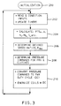
- the process of the algorithms for the microprocessor 108 is shown in Figures 3 to 6 and is somewhat self-explanatory. As seen in Figure 3, the microprocessor undergoes an initialization process at start up (step 200) which establishes the various constants in the parameters needed within the system. The microprocessor 108 then evaluates or interrogates the input signals (step 202) and calculates (step 204) various operating parameters.
- the microprocessor 108 then evaluates any operator commands which might be requesting a ratio change (step 206). Following the evaluation of these commands, the microprocessor 108 establishes (step 208) the pressure levels for the active clutches and then provides for these pressure levels by energizing (step 210) the required pulse-width-modulated solenoid valves 96, 104. This process is repeated on a conventional interrupt basis.
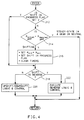
- the microprocessor 108 will follow the programming steps shown in Figure 4 in which it is determined whether the shift command was a forward to reverse command. This involves determining if a shift is in progress (step 212), and where not, determining if the requested gear is the gear actually in use (step 214). If it is, the routine of Figure 4 is left. If not, then the requested gear reading is reset, the shift in progress flag is set, and the timers are cleared at step 216. Then, or if a shift is in progress (step 212), determining if a shift to reverse is required (step 218). If not, the routine of Figure 4 is left after the logic and control sequence are upshifted/downshifted at step 220. If a forward/reverse command is present, the microprocessor performs the control steps (step 222) shown in Figure 5.
- the microprocessor 108 evaluates the vehicle speed to determined if, in fact, the speed is below a threshold value (step 224). If the vehicle speed is above the threshold value, the microprocessor sets a reverse inhibit flag (step 226) and commands a neutral condition (step 228) within the transmission.
- the microprocessor 108 then executes the commands, as shown in Figure 6, and with a reverse inhibit flag set (step 230), the pulse-width-modulated solenoid valve 96 will be set to establish a zero or exhaust pressure level (step 232) and the pulse-width-modulated solenoid valve 104 will be set to establish a low level pressure at passage 106 (step 234).
- the microprocessor 108 will complete the steps shown in Figure 3 and proceed to re-evaluate the system.
- the microprocessor 108 will perform the steps shown in Figure 5 in which the direction (in reverse) flag is set (step 236), the reverse inhibit flag is cleared (step 238) and a command for reverse shift is set (step 240). With this condition, the microprocessor 108 will evaluate the steps shown in Figure 6 of normal clutch pressure control (step 242) and line pressure (step 244) which will result in the higher pressure level being established in passage 106 and reverse shift signal passage 84. The microprocessor 108 will then adjust the duty cycles of the pulse-width-modulated solenoid valves 96 and 104 accordingly, so that a forward to reverse shift will occur.
Abstract
Description
- This invention relates to servo mechanisms, and more particularly, to servo mechanisms for controlling the shifting of a transmission between a forward ratio and a reverse ratio.
- The use of countershaft type transmissions as automatic shifting transmissions is increasing. Such transmissions, as is well known, are generally structurally similar to manually shifted transmissions wherein the synchronizer type clutches have been replaced with fluid operated type clutches. The one remaining mechanical clutch in these systems is generally utilized during forward or reverse operation to establish drive connection between the lowest forward ratio gear and the output shaft and the reverse ratio gear and its meshing idler. Also, these clutches are generally dog type or jaw clutches which do not incorporate a synchronizer. Therefore, it is somewhat important that the gears and the shaft be either rotating at the same speed or that both are stationary. An example of the prior art is shown in US Patent No. 3,557,918.
- A forward/reverse servo controller in accordance with the present invention is characterised by the features specified in the characterising portion of claim 1.
- The present invention provides a control system and a mechanical forward/reverse clutch mechanism which ensures that a minimum speed differential, between a reverse gear member and a transmission shaft, is present prior to engaging the mechanical clutch between the transmission shaft and the reverse gear member.
- A shift control structure includes a servo member operatively connected with a portion of the mechanical clutch to provide for the shifting of the clutch. The servo includes a piston which cooperates with a housing to provide two fluid chambers which are selectively disposed for controlled fluid communication.
- In the forward select position, the chambers are disconnected and in the reverse select position, the chambers are interconnected. The servo is urged to the forward select position by a spring which has sufficient precompression to resist the movement of the piston to the reverse select position prior to the fluid pressure in one of the chambers being increased above a desired threshold level.
- The fluid pressure which is supplied to the chamber is preferably provided by an electro-hydraulic control system which includes a microprocessor and a line pressure regulator. The microprocessor evaluates various vehicle parameters including engine speed, engine torque and vehicle speed. These parameters are evaluated by the microprocessor in a manner to establish a voltage signal to a pulse-width-modulated solenoid valve which controls the line pressure for the transmission hydraulic components in accordance with the duty cycle of the signal.
- If the vehicle speed, for example, is above a certain value and the forward to reverse shift is commanded by the operator, the line pressure will not be sufficient to cause the piston to move against the spring. Accordingly, a forward/reverse shift will not occur and, as a general rule, the transmission will be placed in neutral by exhausting the various friction clutches.
- The microprocessor, as is well known, continuously monitors the operating parameters and the operating requests, such that when the vehicle speed, for example, has been reduced below a threshold value, the line pressure will be increased sufficiently to cause the servo piston to move to the reverse select position and therefore selectively clutch the transmission shaft to the reverse gear. After the reverse select position has been attained, the two chambers are fluidly interconnected and a fluid pressure in the second chamber is directed to a friction clutch and a control valve to establish or otherwise enforce the engagement of the friction clutch which will condition the transmission for reverse drive operation.
- It is therefore an object of this invention to provide an improved forward/reverse servo controller in which a forward to reverse shift is not possible when at least one vehicle operating parameter is above a predetermined threshold value.
- It is another object of this invention to provide an improved forward/reverse servo controller having a dual area piston in which one area thereof is in fluid communication with the line pressure which is controlled to at least two pressure levels, the first of which is not sufficient to cause movement of the piston and the second of which is sufficient to cause such movement, and further wherein, the line pressure level is controlled by a vehicle operating parameter which maintains the line pressure at the low level until a predetermined threshold value is present.
- The present invention will now be described, by way of example, with reference to the following description, and the accompanying drawings, in which:-
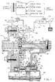
- Figure 1 is a cross-sectional view of a portion of a transmission gear mechanism and servo controller and a schematic representation of an electro-hydraulic control mechanism;
- Figure 2 is a view similar to Figure 1, wherein the shift control mechanism is shown in an alternate position; and
- Figures 3 to 6 are block diagrams of a portion of the operating sequence of a microprocessor utilized to control the fluid pressure and shift control functions of the transmission.
- Referring to the drawings, and more particularly to Figures 1 and 2, there is seen a forward/reverse servo controller, hereinafter referred to as
servo 10, generally designated 10, which includes a casing orhousing 12, anend cover 14, apiston 16 and acompression spring 18. Thepiston 16 is slidably disposed in thehousing 12 and is urged rightward to the position shown in Figure 1 by thespring 18 which is compressed between thehousing 12 and theend cover 14. - The
piston 16 has three circumferentially extendingsurfaces Circumferential surface 20 is slidably sealingly engaged in abore 26 formed in thehousing 12 and forms the outer surface for apiston rod 28, which has secured thereto ashift fork 30 by means of a threadedfastener 32. Thecircumferential surface 22 sealingly engages asurface 34 formed on thehousing 12 and cooperates therewith to define afirst fluid chamber 36. Thecircumferential surface 24 has disposed thereon aseal member 38 which cooperates with asurface 40 formed on thehousing 12 to define asecond fluid chamber 42 and athird fluid chamber 44. Thesecond fluid chamber 42 is formed on the same side of thepiston 16 as thefirst fluid chamber 36 and thethird fluid chamber 44 is disposed on the opposite side of thepiston 16. - The
circumferential surface 22 is in fluid communication with aradial passage 46, anaxial passage 48 and anotherradial passage 50. Theradial passage 50 is open to exhaust in the position shown in Figure 1, which thereby exhausts the fluid pressure in thesecond fluid chamber 42. - In the position shown in Figure 2, the
radial passage 50 is sealed by the sealing engagement between thecircumferential surface 20 and bore 26. In fact, theradial passage 50 is disposed to be closed from atmosphere when thecircumferential surface 22 is moved out of sealing engagement with thesurface 34. - The
shift fork 30 is operatively connected to anannular clutch sleeve 52 which has a splinedinner diameter 54. The splinedinner diameter 54 is adapted to mesh continuously with a splinedouter diameter 56 of aclutch hub 58, which in turn, is drivingly connected through asplined connection 60 with atransmission shaft 62. - The splined
inner diameter 54 ofclutch sleeve 52 is also selectively engageable with aspline 64 formed on aforward gear 66, as seen in Figure 1, and with aspline 68 formed on areverse gear 70, as seen in Figure 2. The forward andreverse gears transmission shaft 62 by bearingmembers - From the above description, it should be apparent that the
forward gear 66 is drivingly connected with thetransmission shaft 62 when theservo 10 is in the forward select position shown in Figure 1. It should also be obvious that in this position, thereverse gear 70 is freely rotatable on thetransmission shaft 62. It should likewise be apparent that when theservo 10 is moved to the reverse select position shown in Figure 2, that thereverse gear 70 is drivingly connected to thetransmission shaft 62 while theforward gear 66 is freely rotatable on thetransmission shaft 62. The forward andreverse gears clutch hub 58 are controlled to their axial positions on thetransmission shaft 62 by a pair ofthrust bearings sleeve shaft 80 and bearing 82, respectively. - The
first fluid chamber 36 is in fluid communication with a reverseshift signal passage 84 which receives a selective signal from aconventional shift controller 86. Thesecond fluid chamber 42 is in fluid communication with aclutch fill passage 88 which is in fluid communication through a one-way orcheck valve 90 with aclutch valve passage 92. Theclutch valve passage 92 is selectively pressurizable to control the engagement of a conventional, fluid operated,friction clutch 94. The fluid pressure in thefriction clutch 94 is controlled by a conventional pulse-width-modulator type solenoid valve 96 (PWM). Thecheck valve 90 will prevent fluid flow from theclutch valve passage 92 to exhaust through the passages in thepiston rod 28 when the forward select position is established. Thus, thefriction clutch 94 can also be used for a forward ratio. - The
third fluid chamber 44 is in fluid communicatoin with apressure passage 98 which is pressurized by theshift controller 86 and at least the first or lowest forward speed transmission operation. Theshift controller 86 receives fluid pressure from a linepressure regulator valve 100 which is supplied by a conventionalpositive displacement pump 102. The linepressure regulator valve 100 is a conventional valve which is controlled by a conventional pulse-width-modulated solenoid valve 104 (PWM) to establish a controlled pressure level in apassage 106 which is connected with theshift controller 86. - The pulse-width-modulated
solenoid valves digital computer 108. Themicroprocessor 108 is effective to receive input signals, such asvehicle speed 110,engine speed 112,engine torque 114 andoperating temperature 116. Obviously, other vehicle parameters can be input to themicroprocessor 108 depending upon the program which is to be executed by themicroprocessor 108. - As is well known, the
microprocessor 108 is effective to provide output signals, in accordance with its programming, and input signals which can be utilized to control the pulse-width-modulatedsolenoid valves output signals 118. - The
microprocessor 108 is effective to control the linepressure regulator valve 100 to establish at least two distinct pressure levels in thepassage 106 and therefore in the reverseshift signal passage 84. As an example, the pressure level inpassage 84 can be controlled at a low level, for example, 450 kpa, and at a high level, for example, 900 kpa. At the low level, the fluid pressure influid chamber 36 is not sufficient to overcome the precompression force inspring 18 and thereforeservo 10 will remain in the forward select position shown in Figure 1. However, when the pressure level in reverseshift signal passage 84 is at the higher level, the fluid pressure in thefluid chamber 36 is sufficient to cause movement of theservo 10 from the forward select position of Figure 1 to the reverse position of Figure 2. - When the
circumferential surface 22 clears thesurface 34, the fluid influid chamber 36 is connected to the fluid inchamber 42 and via clutch fill andclutch valve passages friction clutch 94. Thefriction clutch 94 will in turn be selectively engaged at a pressure level established by the pulse-width-modulatedsolenoid valve 96. When thecircumferential surface 22 has cleared thesurface 34 and the first and secondfluid chambers shift signal passage 84 can, if desired, be reduced to the low level since the combined area of the first and secondfluid chambers spring 18. - The pressure level in reverse
shift signal passage 84 is controlled such that if the operator commands or requests a forward to reverse shift, the command will not be acted upon unless certain vehicle parameters are at or below a predetermined threshold. Themicroprocessor 108 operates in accordance with its programming to establish the pressure level inpassage 106 and therefore reverseshift signal passage 84. - The process of the algorithms for the
microprocessor 108 is shown in Figures 3 to 6 and is somewhat self-explanatory. As seen in Figure 3, the microprocessor undergoes an initialization process at start up (step 200) which establishes the various constants in the parameters needed within the system. Themicroprocessor 108 then evaluates or interrogates the input signals (step 202) and calculates (step 204) various operating parameters. - The
microprocessor 108 then evaluates any operator commands which might be requesting a ratio change (step 206). Following the evaluation of these commands, themicroprocessor 108 establishes (step 208) the pressure levels for the active clutches and then provides for these pressure levels by energizing (step 210) the required pulse-width-modulatedsolenoid valves - If a shift has been commanded by the operator at
step 206, themicroprocessor 108 will follow the programming steps shown in Figure 4 in which it is determined whether the shift command was a forward to reverse command. This involves determining if a shift is in progress (step 212), and where not, determining if the requested gear is the gear actually in use (step 214). If it is, the routine of Figure 4 is left. If not, then the requested gear reading is reset, the shift in progress flag is set, and the timers are cleared atstep 216. Then, or if a shift is in progress (step 212), determining if a shift to reverse is required (step 218). If not, the routine of Figure 4 is left after the logic and control sequence are upshifted/downshifted atstep 220. If a forward/reverse command is present, the microprocessor performs the control steps (step 222) shown in Figure 5. - As seen in Figure 5, the
microprocessor 108 evaluates the vehicle speed to determined if, in fact, the speed is below a threshold value (step 224). If the vehicle speed is above the threshold value, the microprocessor sets a reverse inhibit flag (step 226) and commands a neutral condition (step 228) within the transmission. - The
microprocessor 108 then executes the commands, as shown in Figure 6, and with a reverse inhibit flag set (step 230), the pulse-width-modulatedsolenoid valve 96 will be set to establish a zero or exhaust pressure level (step 232) and the pulse-width-modulatedsolenoid valve 104 will be set to establish a low level pressure at passage 106 (step 234). Themicroprocessor 108 will complete the steps shown in Figure 3 and proceed to re-evaluate the system. - If the operator has commanded a forward/reverse shift (step 218), and vehicle speed decreases below the threshold value (step 224), the
microprocessor 108 will perform the steps shown in Figure 5 in which the direction (in reverse) flag is set (step 236), the reverse inhibit flag is cleared (step 238) and a command for reverse shift is set (step 240). With this condition, themicroprocessor 108 will evaluate the steps shown in Figure 6 of normal clutch pressure control (step 242) and line pressure (step 244) which will result in the higher pressure level being established inpassage 106 and reverseshift signal passage 84. Themicroprocessor 108 will then adjust the duty cycles of the pulse-width-modulatedsolenoid valves - It should be appreciated from the foregoing discussion and description of operation that the splined connections between the
clutch sleeve 52 and thereverse gear 70 will not undergo significant shock loading during a forward to reverse shift since theservo 10 will prevent such shifting until the proper vehicle parameters are present.
Claims (3)
- A forward/reverse servo controller in a shift mechanism comprising a transmission shaft (62); a forward gear (66); a reverse gear (70); clutch means (52,58) including a shift fork (30) movable to a first position for connecting the forward gear to the transmission shaft and to a second position for connecting the reverse gear to the transmission shaft; a fluid operated piston (16) for controlling movement of the shift fork between the first and second positions; and housing means (12,14) for enclosing the piston and cooperating therewith to form a first fluid chamber (36) on one side of the piston, and a second fluid chamber (42) on the one side of the piston; characterised by spring means (18) disposed between the housing means and the piston for urging the piston to move the shift fork to the first position and to position the piston in the housing means with the first chamber sealed from fluid communication with the second chamber; and fluid pressure source means (100,102) selectively connectible with the first chamber for providing a fluid pressure controlled at a first pressure level insufficient to move the piston against the spring means and controlled at a second level pressure sufficient to move the piston against the spring means to move the shift fork to the second position and to establish fluid communication between the first and second fluid chambers, and the first pressure level then being sufficient to maintain the piston and the shift fork in the second position.
- A forward/reverse servo controller as claimed in Claim 1, further including fluid operated clutch means (94) for establishing a reverse ratio; the second fluid chamber (42) being in fluid communication with the fluid operated clutch means, and the fluid operated clutch means being engaged by fluid pressure delivered through the second fluid chamber from the first fluid chamber (36).
- A forward/reverse servo controller as claimed in Claim 1 or Claim 2, wherein the housing means (12,14) cooperates with the piston (16) to form a third fluid chamber (44) on an opposite side of the piston to the first and second fluid chambers (36,42); the fluid pressure source means being selectively connectible with the third fluid chamber for providing a controlled pressure to the third fluid chamber to assist the spring means (18) to move the piston and the shift fork (30) to the first position.
Applications Claiming Priority (2)
| Application Number | Priority Date | Filing Date | Title |
|---|---|---|---|
| US593728 | 1990-10-05 | ||
| US07/593,728 US5046592A (en) | 1990-10-05 | 1990-10-05 | Servo shift control for a forward/reverse mechanism |
Publications (2)
| Publication Number | Publication Date |
|---|---|
| EP0478968A2 true EP0478968A2 (en) | 1992-04-08 |
| EP0478968A3 EP0478968A3 (en) | 1992-12-23 |
Family
ID=24375903
Family Applications (1)
| Application Number | Title | Priority Date | Filing Date |
|---|---|---|---|
| EP19910114816 Withdrawn EP0478968A3 (en) | 1990-10-05 | 1991-09-03 | Servo controller for a forward/reverse mechanism |
Country Status (5)
| Country | Link |
|---|---|
| US (1) | US5046592A (en) |
| EP (1) | EP0478968A3 (en) |
| JP (1) | JPH0674332A (en) |
| KR (1) | KR940001995B1 (en) |
| CA (1) | CA2043634C (en) |
Cited By (1)
| Publication number | Priority date | Publication date | Assignee | Title |
|---|---|---|---|---|
| EP0681120A1 (en) * | 1994-05-05 | 1995-11-08 | Eaton Corporation | Reverse engagement interlock control |
Families Citing this family (12)
| Publication number | Priority date | Publication date | Assignee | Title |
|---|---|---|---|---|
| US5476164A (en) * | 1994-09-12 | 1995-12-19 | Regal-Beloit Corporation | Solenoid actuated mechanical clutch |
| AT401964B (en) * | 1995-04-26 | 1997-01-27 | Steyr Daimler Puch Ag | HYDRAULIC ACTUATOR AND CLUTCH EQUIPPED WITH IT |
| US6450051B1 (en) * | 2000-09-01 | 2002-09-17 | Zf Meritor, Llc | Spring loaded transmission auxiliary piston |
| US7048104B2 (en) * | 2003-09-12 | 2006-05-23 | Ford Global Technologies, Llc | Selective bypass of solenoid-controlled supply to friction elements of an automatic transmission |
| US8661925B2 (en) * | 2007-04-30 | 2014-03-04 | Parker Hannifin Corporation | Hydraulically operated shifter for power take-off |
| DE102014011176A1 (en) * | 2014-07-31 | 2016-02-04 | Fte Automotive Gmbh | Hydraulic actuator for actuating actuators in a motor vehicle transmission |
| DE102014218311A1 (en) * | 2014-09-12 | 2016-03-17 | Volkswagen Aktiengesellschaft | Intermediate gear arrangement for a motor vehicle transmission |
| US9631723B2 (en) | 2015-01-26 | 2017-04-25 | Ford Global Technologies, Llc | Vehicle and method to control rolling engagements |
| CN105065653B (en) * | 2015-07-15 | 2017-09-01 | 徐州南普机电科技有限公司 | A kind of gear selection mechanism of electric car two speed transmission |
| DE102015221999A1 (en) * | 2015-11-09 | 2017-05-11 | Zf Friedrichshafen Ag | Arrangement for actuating at least one switching element |
| US10330191B2 (en) * | 2016-02-22 | 2019-06-25 | Deere & Company | Double disconnect transmission reverser with disconnect synchronizer |
| US10612650B2 (en) | 2016-02-22 | 2020-04-07 | Deere & Company | Double disconnect transmission reverser with disconnect synchronizer |
Citations (2)
| Publication number | Priority date | Publication date | Assignee | Title |
|---|---|---|---|---|
| GB1142506A (en) * | 1966-04-04 | 1969-02-12 | Dewandre Co Ltd C | Improvements in or relating to air pressure actuators for gear change mechanisms |
| US3557918A (en) * | 1969-02-26 | 1971-01-26 | Honda Motor Co Ltd | Apparatus for controlling the operation of a shift member and input clutch in a gear type transmission |
Family Cites Families (10)
| Publication number | Priority date | Publication date | Assignee | Title |
|---|---|---|---|---|
| US2189679A (en) * | 1935-06-25 | 1940-02-06 | Bendix Westinghouse Automotive | Gear shifting mechanism |
| US2137959A (en) * | 1936-01-03 | 1938-11-22 | Bendix Westinghouse Automotive | Gear shifting mechanism |
| US2137953A (en) * | 1936-11-04 | 1938-11-22 | Bendix Westinghouse Automotive | Control mechanism |
| CH238203A (en) * | 1942-09-21 | 1945-06-30 | Boehringer Gmbh Geb | Drive device. |
| US3001413A (en) * | 1957-06-26 | 1961-09-26 | Daimler Benz Ag | Transmission including disengaging clutch construction |
| US3386543A (en) * | 1965-09-08 | 1968-06-04 | Kearney & Trecker Corp | Machine tool transmission and control mechanism |
| BE691051A (en) * | 1965-12-23 | 1967-05-16 | ||
| DE2104934A1 (en) * | 1971-02-03 | 1972-08-17 | Bosch Gmbh Robert | Control device for actuating a vehicle friction clutch |
| SE8403347L (en) * | 1984-06-21 | 1985-12-22 | Volvo Ab | MOTOR VEHICLE COUPLING FOR A MECHANICAL, STEP SWITCHED AUTOMATIC GEAR |
| JPH0619192B2 (en) * | 1985-05-07 | 1994-03-16 | 自動車機器株式会社 | Automatic clutch device |
-
1990
- 1990-10-05 US US07/593,728 patent/US5046592A/en not_active Expired - Lifetime
-
1991
- 1991-06-05 CA CA002043634A patent/CA2043634C/en not_active Expired - Fee Related
- 1991-09-03 EP EP19910114816 patent/EP0478968A3/en not_active Withdrawn
- 1991-09-27 KR KR1019910016889A patent/KR940001995B1/en not_active IP Right Cessation
- 1991-10-04 JP JP3258034A patent/JPH0674332A/en active Pending
Patent Citations (2)
| Publication number | Priority date | Publication date | Assignee | Title |
|---|---|---|---|---|
| GB1142506A (en) * | 1966-04-04 | 1969-02-12 | Dewandre Co Ltd C | Improvements in or relating to air pressure actuators for gear change mechanisms |
| US3557918A (en) * | 1969-02-26 | 1971-01-26 | Honda Motor Co Ltd | Apparatus for controlling the operation of a shift member and input clutch in a gear type transmission |
Cited By (1)
| Publication number | Priority date | Publication date | Assignee | Title |
|---|---|---|---|---|
| EP0681120A1 (en) * | 1994-05-05 | 1995-11-08 | Eaton Corporation | Reverse engagement interlock control |
Also Published As
| Publication number | Publication date |
|---|---|
| KR920008374A (en) | 1992-05-27 |
| EP0478968A3 (en) | 1992-12-23 |
| CA2043634A1 (en) | 1992-04-06 |
| KR940001995B1 (en) | 1994-03-12 |
| US5046592A (en) | 1991-09-10 |
| CA2043634C (en) | 1994-10-04 |
| JPH0674332A (en) | 1994-03-15 |
Similar Documents
| Publication | Publication Date | Title |
|---|---|---|
| US4547178A (en) | Control system for an automatic transmission for a vehicle | |
| US4867732A (en) | Control device for belt-and-pulley type continuously variable transmission for a vehicle | |
| KR920005482B1 (en) | Control apparatus for automatic transmission gear system for vehicle | |
| EP3217041B1 (en) | Lubricating system for engagement mechanism | |
| US5046592A (en) | Servo shift control for a forward/reverse mechanism | |
| US5345843A (en) | Speed change control apparatus and method for an automotive automatic transmission | |
| EP1271006B1 (en) | Automatic transmission control system | |
| US3688607A (en) | Transmission and control | |
| EP1205690B1 (en) | Control apparatus of an automated manual transmission | |
| US10738883B2 (en) | Controller of power transmission system for vehicle | |
| KR20080027738A (en) | Variable speed control device for automatic transmission | |
| JPH11230332A (en) | Fluid auxiliary shift device and method of mechanical transmission | |
| EP0051918B1 (en) | Variable-ratio drive mechanisms | |
| US4738159A (en) | Four-wheel drive automatic transmission | |
| US5643123A (en) | Electronic and hydraulic control system of a 4-speed automatic transmission for automotive vehicle and method for controlling hydraulic pressure | |
| US4785690A (en) | Pressure regulating system for use in an automatic transmission | |
| US5143191A (en) | Coupling force control system for fluid coupling | |
| US5186294A (en) | Control method for the engagement of a torque converter clutch | |
| US5157993A (en) | Hybrid continuously variable transmission with electronically controlled clutch | |
| US4787471A (en) | Power transmitting system for a four-wheel drive vehicle | |
| US4623053A (en) | Control device for a direct-coupling hydraulic clutch in a hydraulic torque converter | |
| EP0477545B1 (en) | Shift control system for an automatic transmission | |
| US3618727A (en) | Overlap valve | |
| GB2152162A (en) | Control system for an automatic continuously variable transmission for a vehicle | |
| EP0684910B1 (en) | A hydraulic control system for automatic transmission |
Legal Events
| Date | Code | Title | Description |
|---|---|---|---|
| PUAI | Public reference made under article 153(3) epc to a published international application that has entered the european phase |
Free format text: ORIGINAL CODE: 0009012 |
|
| AK | Designated contracting states |
Kind code of ref document: A2 Designated state(s): DE FR GB |
|
| PUAL | Search report despatched |
Free format text: ORIGINAL CODE: 0009013 |
|
| AK | Designated contracting states |
Kind code of ref document: A3 Designated state(s): DE FR GB |
|
| 17P | Request for examination filed |
Effective date: 19921124 |
|
| 17Q | First examination report despatched |
Effective date: 19940420 |
|
| STAA | Information on the status of an ep patent application or granted ep patent |
Free format text: STATUS: THE APPLICATION IS DEEMED TO BE WITHDRAWN |
|
| 18D | Application deemed to be withdrawn |
Effective date: 19950404 |