EP0478967B1 - Self-adjusting hydraulic valve tappet - Google Patents
Self-adjusting hydraulic valve tappet Download PDFInfo
- Publication number
- EP0478967B1 EP0478967B1 EP91114807A EP91114807A EP0478967B1 EP 0478967 B1 EP0478967 B1 EP 0478967B1 EP 91114807 A EP91114807 A EP 91114807A EP 91114807 A EP91114807 A EP 91114807A EP 0478967 B1 EP0478967 B1 EP 0478967B1
- Authority
- EP
- European Patent Office
- Prior art keywords
- bore
- wall
- hollow cylindrical
- guide sleeve
- valve tappet
- Prior art date
- Legal status (The legal status is an assumption and is not a legal conclusion. Google has not performed a legal analysis and makes no representation as to the accuracy of the status listed.)
- Expired - Lifetime
Links
- 239000003921 oil Substances 0.000 claims description 34
- 238000002485 combustion reaction Methods 0.000 claims description 6
- 239000010687 lubricating oil Substances 0.000 claims description 3
- 230000002093 peripheral effect Effects 0.000 claims description 2
- 239000000463 material Substances 0.000 claims 2
- 238000006073 displacement reaction Methods 0.000 claims 1
- 239000002245 particle Substances 0.000 description 2
- 239000002861 polymer material Substances 0.000 description 2
- 238000009423 ventilation Methods 0.000 description 2
- 238000009434 installation Methods 0.000 description 1
- 239000002184 metal Substances 0.000 description 1
Images


Classifications
-
- F—MECHANICAL ENGINEERING; LIGHTING; HEATING; WEAPONS; BLASTING
- F01—MACHINES OR ENGINES IN GENERAL; ENGINE PLANTS IN GENERAL; STEAM ENGINES
- F01L—CYCLICALLY OPERATING VALVES FOR MACHINES OR ENGINES
- F01L1/00—Valve-gear or valve arrangements, e.g. lift-valve gear
- F01L1/20—Adjusting or compensating clearance
- F01L1/22—Adjusting or compensating clearance automatically, e.g. mechanically
- F01L1/24—Adjusting or compensating clearance automatically, e.g. mechanically by fluid means, e.g. hydraulically
- F01L1/245—Hydraulic tappets
- F01L1/25—Hydraulic tappets between cam and valve stem
-
- Y—GENERAL TAGGING OF NEW TECHNOLOGICAL DEVELOPMENTS; GENERAL TAGGING OF CROSS-SECTIONAL TECHNOLOGIES SPANNING OVER SEVERAL SECTIONS OF THE IPC; TECHNICAL SUBJECTS COVERED BY FORMER USPC CROSS-REFERENCE ART COLLECTIONS [XRACs] AND DIGESTS
- Y10—TECHNICAL SUBJECTS COVERED BY FORMER USPC
- Y10T—TECHNICAL SUBJECTS COVERED BY FORMER US CLASSIFICATION
- Y10T74/00—Machine element or mechanism
- Y10T74/21—Elements
- Y10T74/2101—Cams
- Y10T74/2107—Follower
Definitions
- the invention relates to an automatically hydraulically adjusting valve lifter according to DE-A-37 13 351, which is arranged in a guide bore of a cylinder head of an internal combustion engine, and which consists of a cup-shaped housing which comprises a hollow cylindrical wall which at one end through a floor is closed, against which a control cam runs from the outside, and which has a cylindrical guide sleeve which is concentric with the hollow cylindrical wall and which, at its end facing away from the floor, opens into the center of a disk part which merges with its outer circumference into the hollow cylindrical wall of the housing, wherein the actual hydraulic lash adjuster is guided in a longitudinally displaceable manner in the guide sleeve, and an annular oil storage space is delimited by the hollow cylindrical wall, the cylindrical guide sleeve, the bottom and the disk part, which is delimited by a in the hollow cylindrical wall ng arranged hole is supplied with oil from the lubricating oil circuit of the internal combustion engine, and which has a vent hole in a boundary wall.
- the invention has for its object to provide a vent hole with a comparatively large cross-section in a generic tappet, in which consequently there is no risk of clogging, but care should be taken to ensure that the leakage of oil remains within narrow limits.
- This object is achieved by the invention in that at a point of a wall delimiting the oil reservoir, which at least during the phase in which the control cam rests with its base circle against the bottom of the valve tappet, is in sliding contact with an adjacent component, which in the Wall and the component delimiting vent hole is provided, and an oil channel extending from the vent hole is provided, which is guided into the vicinity of the floor.
- the throttle in the form of the sliding gap which is connected downstream of the bore, which can have a relatively large cross section, ensures that air in the pressure chamber is unimpeded, but oil can only escape to an extremely small extent because of its higher viscosity.
- the bore can be provided, for example, in the hollow cylindrical wall and open into the sliding gap between this wall and the guide bore of the cylinder head.
- a channel can be provided in the interior of the oil reservoir, which connects to the bore and ends near the bottom.
- a particularly expedient embodiment also results from the fact that the cylindrical guide sleeve and the disk part are formed by a one-piece component, on the outer edge of which a cylindrical collar is integrally formed, which fits tightly against the inner wall of the hollow cylindrical wall, but at the peripheral points, at which the oil inlet hole and the ventilation hole are provided in the wall, forming a longitudinal channel open near the floor at a distance from the wall.
- Such a component can either be designed as a sheet metal part or as a molded part made of polymer material.
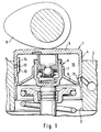
- Figure 1 shows a hydraulic tappet 1, which is arranged in a guide bore 2 of the cylinder head 3 of an internal combustion engine, and which consists of a housing which comprises a hollow cylindrical wall 4 which is closed at the upper end by a bottom 5 against which outside of the control cam 6 starts.
- the cup tappet has in its interior a cylindrical guide sleeve 7 which is concentric with the hollow cylindrical wall 4 and opens at its end facing away from the base 5 into the center of a disk part 8 which merges with the outer circumference into the hollow cylindrical wall 4 of the housing.
- the actual hydraulic play compensation element 9 is guided in a longitudinally displaceable manner in the guide sleeve 7.
- the hollow cylindrical wall 4, the cylindrical guide sleeve 7, the base 5 and the disk part 8, and partly the hydraulic lash adjuster 9, define an annular oil reservoir 10 which supplies oil from the lubricating oil circuit of the internal combustion engine through a bore 11 arranged in the hollow cylindrical wall 4 is.
- a vent hole 12 is provided in the hollow cylindrical wall 4, preferably diametrically opposite the oil inlet hole 11, which opens into the sliding gap between the hollow cylindrical wall 4 on the one hand and the guide hole 2 on the other.
- This vent hole 12 is provided at such a point that it is in sliding contact with the guide hole 2, particularly during the phase in which the control cam 6 bears with its base circle against the bottom 5 of the valve lifter 1.
- a molded part 13 is mounted in the interior of the oil reservoir 10, which covers the vent hole 12 and forms a channel 14 which is open near the bottom.
- FIG. 2 differs from that of Figure 1 essentially in that the cylindrical guide sleeve 7 and the disc base 8 are formed as a one-piece component, on the outer edge of which a cylindrical collar 15 is integrally formed, which is close to the Creates inner wall of the hollow cylindrical wall 4, but at the circumferential points at which the oil inlet bore 11 and the vent bore 12 are provided in the wall 4, runs at a distance from the wall, forming a longitudinal groove 16 ending near the bottom.
- a component 17 made of polymer material is inserted into the inside of the plunger, which component forms the cylindrical guide sleeve and the disk part at the same time.
- the hydraulic lash adjuster 9 is guided in this component 17 by an inserted metallic guide bushing 18.
- Oil storage space 10 ends and thus prevents the oil storage space from running empty at a standstill.
- the component 17 forms a channel 20 that is open toward the bottom 5.
- FIG. 4 differs from the previous one only in that here the vent hole 21 is provided in the guide bush 18 and thus opens into the sliding gap between this guide bush 18 on the one hand and the hydraulic play compensation element 9 on the other hand.
- a duct 22 leading to the bottom 5 connects to the vent hole 21 provided in the guide bushing 18 in the component 17.
Description
Die Erfindung betrifft einen sich selbsttätig hydraulisch einstellenden Ventilstößel gemäß DE-A-37 13 351, der in einer Führungsbohrung eines Zylinderkopfes einer Brennkraftmaschine angeordnet ist, und der aus einem tassenförmigen Gehäuse besteht, welches eine hohlzylindrische Wandung umfaßt, die am einen Ende durch einen Boden verschlossen ist, gegen den von außen ein Steuernocken anläuft, und welches eine zu der hohlzylindrischen Wandung konzentrische zylindrische Führungshülse aufweist, die an ihrem dem Boden abgewandten Ende in das Zentrum eines Scheibenteiles mündet, welches mit seinem Außenumfang in die hohlzylindrische Wandung des Gehäuses übergeht, wobei in der Führungshülse das eigentliche hydraulische Spielausgleichselement längsverschieblich geführt ist, und wobei durch die hohlzylindrische Wandung, die zylindrische Führungshülse, den Boden und das Scheibenteil ein ringförmiger Ölvorratsraum begrenzt ist, der durch eine in der hohlzylindrischen Wandung angeordnete Bohrung mit Öl aus dem Schmierölkreislauf der Brennkraftmaschine versorgt ist, und der in einer Begrenzungswand eine Entlüftungsbohrung aufweist.The invention relates to an automatically hydraulically adjusting valve lifter according to DE-A-37 13 351, which is arranged in a guide bore of a cylinder head of an internal combustion engine, and which consists of a cup-shaped housing which comprises a hollow cylindrical wall which at one end through a floor is closed, against which a control cam runs from the outside, and which has a cylindrical guide sleeve which is concentric with the hollow cylindrical wall and which, at its end facing away from the floor, opens into the center of a disk part which merges with its outer circumference into the hollow cylindrical wall of the housing, wherein the actual hydraulic lash adjuster is guided in a longitudinally displaceable manner in the guide sleeve, and an annular oil storage space is delimited by the hollow cylindrical wall, the cylindrical guide sleeve, the bottom and the disk part, which is delimited by a in the hollow cylindrical wall ng arranged hole is supplied with oil from the lubricating oil circuit of the internal combustion engine, and which has a vent hole in a boundary wall.
Bei solchen und ähnlichen hydraulischen Ventilstößeln ist es bereits bekannt geworden, aus dem Ölvorratsraum nach außen führende Entlüftungsbohrungen vorzusehen. Dabei hat man in der Regel Bohrungen mit extrem geringem Querschnitt vorgesehen, um zu verhindern, daß durch diese Bohrungen neben Luft auch eine größere Menge Öl austritt. Aus dem Vorratsraum austretendes Öl muß durch aus dem Ölkreislauf nachfließendes Öl ersetzt werden, wobei jedoch gleichzeitig auch Schmutzpartikel und Luftanteile in den Ölvorratsraum gelangen.With such and similar hydraulic valve lifters, it has already become known to provide ventilation bores leading out of the oil reservoir. In general, holes with an extremely small cross-section have been provided in order to prevent a large amount of oil from escaping through these holes in addition to air. Oil emerging from the storage room must be replaced by oil flowing out of the oil circuit Oil are replaced, but at the same time dirt particles and air components get into the oil reservoir.
Man hat z. B. vorgeschlagen, eine aus dem Ölvorratsraum nach außen führende Bohrung so anzuordnen, daß sie während des Ventilhubes durch die Führungsbohrung im Gehäuse abgedeckt ist, während sie in der Phase, in welcher der Steuernocken mit seinem Grundkreis gegen den Boden des Ventilstößels anliegt, freilag. Dies führte dazu, daß während dieser Grundkreisphase durch diese Bohrung in erheblichem Maße Öl austreten konnte. Hätte man dies verhindern wollen und die Bohrung sehr klein gemacht, dann hätte die Gefahr bestanden, daß sich diese enge Bohrung nach kurzer Zeit mit Schmutzpartikeln zusetzt (GB-PS 10 64 338).You have z. B. proposed to arrange a leading from the oil reservoir to the outside hole so that it is covered during the valve stroke by the guide hole in the housing, while it is exposed in the phase in which the control cam bears with its base circle against the bottom of the valve lifter. As a result, oil was able to escape to a considerable extent through this bore during this basic circle phase. If one had wanted to prevent this and made the bore very small, there would have been the danger that this narrow bore would clog with dirt particles after a short time (GB-
Demgegenüber liegt der Erfindung die Aufgabe zugrunde, bei einem gattungsgemäßen Stößel eine Entlüftungsbohrung mit vergleichsweise großem Querschnitt vorzusehen, bei der folglich die Gefahr der Verstopfung nicht besteht, wobei aber dafür gesorgt sein soll, daß dennoch der Austritt von Öl in engen Grenzen bleibt.In contrast, the invention has for its object to provide a vent hole with a comparatively large cross-section in a generic tappet, in which consequently there is no risk of clogging, but care should be taken to ensure that the leakage of oil remains within narrow limits.
Diese Aufgabe löst die Erfindung dadurch, daß an einer Stelle einer den Ölvorratsraum begrenzenden Wand, die wenigstens während der Phase, in welcher der Steuernocken mit seinem Grundkreis gegen den Boden des Ventilstößels anliegt, in Gleitkontakt mit einem angrenzenden Bauteil steht, die in den durch die Wand und das Bauteil begrenzten Gleitspalt mündende Entlüftungsbohrung vorgesehen ist, und ein von der Entlüftungsbohrung ausgehender Ölkanal vorgesehen ist, der bis in die Nähe des Bodens geführt ist.This object is achieved by the invention in that at a point of a wall delimiting the oil reservoir, which at least during the phase in which the control cam rests with its base circle against the bottom of the valve tappet, is in sliding contact with an adjacent component, which in the Wall and the component delimiting vent hole is provided, and an oil channel extending from the vent hole is provided, which is guided into the vicinity of the floor.
Auf diese Weise wird durch die der Bohrung, die relativ großen Querschnitt aufweisen kann, nachgeschaltete Drossel in Form des Gleitspaltes erreicht, daß zwar im Druckraum befindliche Luft ungehindert, Öl wegen seiner höheren Zähigkeit jedoch nur in äußerst geringem Maße austreten kann.In this way, the throttle in the form of the sliding gap, which is connected downstream of the bore, which can have a relatively large cross section, ensures that air in the pressure chamber is unimpeded, but oil can only escape to an extremely small extent because of its higher viscosity.
Zur Erreichung dieses Zieles kann die Bohrung beispielsweise in der hohlzylindrischen Wandung vorgesehen sein und in den Gleitspalt zwischen dieser Wandung und der Führungsbohrung des Zylinderkopfes münden. Es ist aber auch möglich, die Bohrung in der Wandung der zylindrischen Führungshülse vorzusehen und in den Gleitspalt zwischen dieser und dem hydraulischen Spielausgleichselement münden zu lassen. In allen Fällen ist es wünschenswert die Bohrung an einer Stelle des Ölvorratsraumes anzuordnen, die sich in der Nähe des Bodens befindet. Dies ist nicht allen Fällen ohne weiteres möglich, denn wenn man die Bohrung in der hohlzylindrischen Wandung des Tassenstößels vorsieht dann kann sie sich während der Grundkreisphase außerhalb des Gleitspaltes zwischen dieser Wandung und der Führungsbohrung des Zylinderkopfes befinden. In diesem Falle muß die Bohrung in einer größeren Entfernung vom Boden des Stößels angeordnet werden. Um dennoch zu gewährleisten, daß die Luft, die sich während dieser Grundkreisphase, in der sich der Stößel in Ruhe befindet, im oberen bodennahen Bereich ansammelt, sicher abgeführt wird, kann man im Innern des Ölvorratsraumes einen Kanal vorsehen, der sich an die Bohrung anschließt und in der Nähe des Bodens endet.To achieve this goal, the bore can be provided, for example, in the hollow cylindrical wall and open into the sliding gap between this wall and the guide bore of the cylinder head. However, it is also possible to provide the bore in the wall of the cylindrical guide sleeve and to let it open into the sliding gap between the latter and the hydraulic play compensation element. In all cases, it is desirable to locate the hole at a location in the oil reservoir that is near the bottom. This is not readily possible in all cases, because if the bore is provided in the hollow cylindrical wall of the tappet, it can be located outside the sliding gap between this wall and the guide bore of the cylinder head during the base circle phase. In this case, the hole must be located a greater distance from the bottom of the ram. In order to ensure that the air that accumulates in the upper area near the floor during this base circle phase, in which the plunger is at rest, can be safely discharged, a channel can be provided in the interior of the oil reservoir, which connects to the bore and ends near the bottom.
Dies ist in einfacher Weise dadurch möglich, daß die Bohrung an der Innenfläche der hohlzylindrischen Wandung von einem sich in Längsrichtung erstreckenden rinnenförmigen Bauteil überdeckt ist, das an seinem bodenfernen Ende verschlossen und am oberen, bodennahen Ende offen ist.This is possible in a simple manner in that the bore on the inner surface of the hollow cylindrical wall is covered by a longitudinally extending channel-shaped component which is closed at its end remote from the floor and open at the upper end near the floor.
Eine besonders zweckmäßige Ausführung ergibt sich auch dadurch, daß die zylindrische Führungshülse und das Scheibenteil durch ein einstückiges Bauteil gebildet sind, an dessen äußeren Rand einstückig ein zylindrischer Kragen angeformt ist, der sich dicht an die Innenwand der hohlzylindrischen Wandung anlegt, jedoch an den Umfangsstellen, an denen in der Wandung die Ölzulaufbohrung und die Entlüftungsbohrung vorgesehen sind, unter Bildung einer in Bodennähe offenen Längsrinne im Abstand von der Wandung verläuft.A particularly expedient embodiment also results from the fact that the cylindrical guide sleeve and the disk part are formed by a one-piece component, on the outer edge of which a cylindrical collar is integrally formed, which fits tightly against the inner wall of the hollow cylindrical wall, but at the peripheral points, at which the oil inlet hole and the ventilation hole are provided in the wall, forming a longitudinal channel open near the floor at a distance from the wall.
Ein solches Bauteil kann entweder als Blechziehteil, oder auch als Spritzteil aus polymerem Werkstoff ausgebildet sein.Such a component can either be designed as a sheet metal part or as a molded part made of polymer material.
In den Zeichnungen sind Ausführungsbeispiele der Erfindung dargestellt. Es zeigen:
- Fig. 1
- einen Längsschnitt durch einen Ventilstößel in seiner Einbausituation zwischen einem Steuernocken und dem Ventilschaft,
- Fig. 2 bis 4
- Längsschnitte durch Varianten von hydraulischen Ventilstößeln gemäß der Erfindung.
- Fig. 1
- 2 shows a longitudinal section through a valve tappet in its installation situation between a control cam and the valve stem,
- 2 to 4
- Longitudinal sections through variants of hydraulic valve lifters according to the invention.
Die Figur 1 zeigt einen hydraulischen Tassenstößel 1, der in einer Führungsbohrung 2 des Zylinderkopfes 3 einer Brennkraftmaschine angeordnet ist, und der aus einem Gehäuse besteht, welches eine hohlzylindrische Wandung 4 umfaßt, die am oberen Ende durch einen Boden 5 verschlossen ist, gegen den von außen der Steuernocken 6 anläuft. Der Tassenstößel weist in seinem Innern eine zu der hohlzylindrischen Wandung 4 konzentrische zylindrische Führungshülse 7 auf, die an ihren dem Boden 5 abgewandten Ende in das Zentrum eines Scheibenteiles 8 mündet, welches mit seinem Außenumfang in die hohlzylindrische Wandung 4 des Gehäuses übergeht. In der Führungshülse 7 ist das eigentliche hydraulische Spielausgleichselement 9 längsverschieblich geführt. Durch die hohlzylindrische Wandung 4 die zylindrische Führungshülse 7, den Boden 5 und das Scheibenteil 8, sowie teilweise das hydraulische Spielausgleichselement 9 ist ein ringförmiger Ölvorratsraum 10 begrenzt, der durch eine in der hohlzylindrischen Wandung 4 angeordnete Bohrung 11 mit Öl aus dem Schmierölkreislauf der Brennkraftmaschine versorgt ist. Weiterhin ist in der hohlzylindrischen Wandung 4, vorzugsweise diametral gegenüber der Ölzulaufbohrung 11, eine Entlüftungsbohrung 12 vorgesehen, die in den Gleitspalt zwischen der hohlzylindrischen Wandung 4 einerseits und der Führungsbohrung 2 andererseits mündet. Diese Entlüftungsbohrung 12 ist an einer solchen Stelle angebracht, daß sie insbesondere auch während der Phase, in welcher der Steuernocken 6 mit seinem Grundkreis gegen den Boden 5 des Ventilstößels 1 anliegt, in Gleitkontakt mit der Führungsbohrung 2 steht.Figure 1 shows a hydraulic tappet 1, which is arranged in a
Um die Luft, die sich während der Grundkreisphase in Nähe des Bodens 5 ansammelt, sicher abführen zu können, obwohl sich die Entlüftungsbohrung 12 in einem Abstand davon befindet, ist im Innern des Ölvorratsraumes 10 ein Formteil 13 angebracht, welches die Entlüftungsbohrung 12 überdeckt und einen in Bodennähe offenen Kanal 14 bildet.In order to be able to safely discharge the air that accumulates in the vicinity of the
Die in Figur 2 dargestellte Variante unterscheidet sich von der nach Figur 1 im wesentlichen dadurch, daß die zylindrische Führungshülse 7 und das Scheibentel 8 als einstückiges Bauteil gebildet sind, an dessen äußeren Rand einstückig ein zylindrischer Kragen 15 einstückig angeformt ist, der sich dicht an die Innenwand der hohlzylindrischen Wandung 4 anlegt, jedoch an den Umfangsstellen, an denen in der Wandung 4 die Ölzulaufbohrung 11 und die Entlüftungsbohrung 12 vorgesehen sind, unter Bildung einer in Bodennähe endenden Längsrinne 16 im Abstand von der Wandung verläuft.The variant shown in Figure 2 differs from that of Figure 1 essentially in that the
Bei den in den Figuren 3 und 4 dargestellten Varianten ist in das Innere des Stößels ein Bauteil 17 aus polymerem Werkstoff eingesetzt, welches die zylindrische Führungshülse und das Scheibenteil gleichzeitig bildet. Die Führung des hydraulischen Spielausgleichselementes 9 in diesem Bauteil 17 erfolgt durch eine eingesetzte metallische Führungsbuchse 18. Bei der in Figur 3 dargestellten Ausführung weist das Bauteil 17 im Anschluß an die Ölzulaufbohrung 11 einen schräg nach oben gerichteten Kanal 19 auf, der im oberen Bereich des ringförmigen Ölvorratsraumes 10 endet und der damit ein Leerlaufen des Ölvorratsraumes im Stillstand verhindert. Im Bereich der Entlüftungsbohrung 12 bildet das Bauteil 17 einen in Richtung zum Boden 5 hin offenen Kanal 20.In the variants shown in FIGS. 3 and 4, a
Die in Figur 4 dargestellte Ausführung unterscheidet sich von der vorhergehenden lediglich dadurch, daß hier die Entlüftungsbohrung 21 in der Führungsbuchse 18 vorgesehen ist und damit in den Gleitspalt zwischen dieser Führungsbuchse 18 einerseits und dem hydraulischen Spielausgleichselement 9 andererseits mündet. An die in der Führungsbuchse 18 vorgesehene Entlüftungsbohrung 21 schließt sich in dem Bauteil 17 ein zum Boden 5 hin geführter Kanal 22 an.The embodiment shown in FIG. 4 differs from the previous one only in that here the
Claims (7)
- Self-adjusting hydraulic valve tappet (1) arranged in a guide bore (2) of a cylinder head (3) of an internal combustion engine and comprising a cup-shaped housing with a hollow cylindrical wall (4) closed at one end by a bottom (5) against which a control cam (6) runs on the outside, the housing comprising a cylindrical guide sleeve (7, 18) which is concentric with the hollow cylindrical wall and, at its end facing away from the bottom (5), opens into the centre of a disc part (8, 17) whose outer periphery merges into the hollow cylindrical wall (4) of the housing, the actual hydraulic clearance compensation element (9) being guided for longitudinal displacement in the guide sleeve (7, 18), and an annular oil reservoir (10) being delimited by the hollow cylindrical wall (4), the cylindrical guide sleeve (7, 18), the bottom (5) and the disc part (8, 17), which oil reservoir (10) is supplied with oil from the lubricating oil circuit of the internal combustion engine through a bore (11) arranged in the hollow cylindrical wall (4) and comprises a deaeration bore (12, 21) in one delimiting wall, characterised in that, at a point of a wall delimiting the oil reservoir (10) and which is in sliding contact with an adjacent component (3, 9) at least during the phase in which the base circle of the control cam (6) bears against the bottom (5) of the valve tappet (1), there is provided the deaeration bore (12, 21) which opens into the sliding gap defined by the wall and the component (3, 9), and an oil canal (14, 16, 20, 22) is provided which starts from the deaeration bore (12, 21) and extends upto the vicinity of the bottom (5).
- Valve tappet according to claim 1, characterised in that the bore (12) is provided in the hollow cylindrical wall (4) and opens into the sliding gap between this wall (4) and the guide bore (2) of the cylinder head (3).
- Valve tappet according to claim 1, characterised in that the bore (21) is provided in the wall of the cylindrical guide sleeve (18) and opens into the sliding gap between this and the hydraulic clearance compensation element (9).
- Valve tappet according to claim 2, characterised in that, on the inner surface of the hollow cylindrical wall (4), the bore (12) is overlapped by a duct-shaped component (13) extending in the longitudinal direction which is closed at its end away from the bottom and open at its upper end near the bottom.
- Valve tappet according to claim 2, characterised in that the cylindrical guide sleeve (7) and the disc part (8) are constituted by a one-piece component at the outer edge of whereof a cylindrical collar (15) is integrally formed which bears closely against the inner surface of the hollow cylindrical wall (4) but, at the peripheral points where the oil supply bore (11) and the deaeration bore (12) are provided in the wall (4), extends at a distance from the wall (4) thus forming a longitudinal duct (16) opening in the vicinity of the bottom.
- Valve tappet according to claim 2, characterised in that the cylindrical guide sleeve and the disc part are formed by a common component (17) made of a polymeric material which is inserted in a liquid-tight manner into the bore of the hollow cylindrical wall (4) and comprises canals (19, 20) which connect the oil supply bore (11) on the one hand, and the deaeration bore (12) on the other hand, with the region of the oil reservoir (10) near the bottom.
- Valve tappet according to claim 3, characterised in that, in the cylindrical guide sleeve (18), there is provided a deaeration bore (21) which is connected with the region of the oil reservoir near the bottom by a canal (22) arranged in a component (17) made of a polymeric material which forms the cylindrical guide sleeve and the disc part.
Applications Claiming Priority (2)
| Application Number | Priority Date | Filing Date | Title |
|---|---|---|---|
| DE4030987 | 1990-10-01 | ||
| DE4030987A DE4030987A1 (en) | 1990-10-01 | 1990-10-01 | AUTOMATICALLY HYDRAULICALLY ADJUSTING VALVE |
Publications (2)
| Publication Number | Publication Date |
|---|---|
| EP0478967A1 EP0478967A1 (en) | 1992-04-08 |
| EP0478967B1 true EP0478967B1 (en) | 1994-12-07 |
Family
ID=6415335
Family Applications (1)
| Application Number | Title | Priority Date | Filing Date |
|---|---|---|---|
| EP91114807A Expired - Lifetime EP0478967B1 (en) | 1990-10-01 | 1991-09-03 | Self-adjusting hydraulic valve tappet |
Country Status (6)
| Country | Link |
|---|---|
| US (1) | US5117787A (en) |
| EP (1) | EP0478967B1 (en) |
| JP (1) | JPH04234510A (en) |
| BR (1) | BR9104185A (en) |
| DE (2) | DE4030987A1 (en) |
| ES (1) | ES2064839T3 (en) |
Families Citing this family (6)
| Publication number | Priority date | Publication date | Assignee | Title |
|---|---|---|---|---|
| US5280771A (en) * | 1992-09-23 | 1994-01-25 | Eaton Corporation | Direct acting hydraulic tappet |
| US5743224A (en) * | 1993-09-14 | 1998-04-28 | Unisia Jecs Corporation | Valve lifter surface and processing method thereof |
| DE9408473U1 (en) * | 1994-05-21 | 1994-07-21 | Schaeffler Waelzlager Kg | Cup-shaped pestle |
| DE19724563A1 (en) * | 1997-06-11 | 1998-12-17 | Schaeffler Waelzlager Ohg | Cup-shaped valve tappet for gas exchange valve |
| US7992541B2 (en) * | 2006-03-14 | 2011-08-09 | Ford Global Technologies, Llc | System and method for controlling auto-ignition |
| CN103628941B (en) * | 2012-08-24 | 2016-08-17 | 上海通用汽车有限公司 | The hydraulic tappet that valve clearance is automatically adjusted |
Family Cites Families (12)
| Publication number | Priority date | Publication date | Assignee | Title |
|---|---|---|---|---|
| DE659536C (en) * | 1933-11-26 | 1938-05-05 | Eaton Mfg Co | Self-adjusting valve drive |
| DE3421420A1 (en) * | 1983-08-16 | 1985-03-07 | IRM-Antriebstechnik GmbH, 7057 Winnenden | Oil feed with return prevention device for bucket tappets with hydraulic valve clearance adjustment |
| DE3500425A1 (en) * | 1985-01-09 | 1986-07-10 | Motomak Motorenbau, Maschinen- u. Werkzeugfabrik, Konstruktionen GmbH, 8070 Ingolstadt | HYDRAULIC CUPS FOR COMBUSTION ENGINES |
| JPH0746723Y2 (en) * | 1985-06-20 | 1995-10-25 | 日産自動車株式会社 | Hydraulic valve lifter |
| DE3623638C2 (en) * | 1986-07-12 | 1994-02-24 | Schaeffler Waelzlager Kg | Automatically hydraulic valve lifter |
| DE3639911A1 (en) * | 1986-11-22 | 1988-06-01 | Schaeffler Waelzlager Kg | AUTOMATICALLY HYDRAULICALLY ADJUSTING VALVE |
| DE3706006A1 (en) * | 1987-02-25 | 1988-09-08 | Schaeffler Waelzlager Kg | HYDRAULIC GAME COMPENSATION ELEMENT FOR VALVE CONTROLS ON COMBUSTION ENGINES |
| DE3713751A1 (en) * | 1987-04-24 | 1988-11-03 | Opel Adam Ag | Hydraulic clearance adjusting element |
| DE3812333A1 (en) * | 1988-04-14 | 1989-10-26 | Schaeffler Waelzlager Kg | AUTOMATICALLY HYDRAULICALLY ADJUSTING VALVE |
| JPH0727364Y2 (en) * | 1988-05-27 | 1995-06-21 | 株式会社ユニシアジェックス | Hydraulic valve lifter |
| GB8910102D0 (en) * | 1989-05-03 | 1989-06-21 | Jaguar Cars | Hydraulic tappets |
| JPH033905A (en) * | 1989-05-16 | 1991-01-10 | Volkswagen Ag <Vw> | Vertical valve system , especially valve drive device for load alternating valve for internal combustion engine |
-
1990
- 1990-10-01 DE DE4030987A patent/DE4030987A1/en not_active Withdrawn
-
1991
- 1991-08-07 US US07/741,644 patent/US5117787A/en not_active Expired - Fee Related
- 1991-09-03 EP EP91114807A patent/EP0478967B1/en not_active Expired - Lifetime
- 1991-09-03 DE DE59103788T patent/DE59103788D1/en not_active Expired - Fee Related
- 1991-09-03 ES ES91114807T patent/ES2064839T3/en not_active Expired - Lifetime
- 1991-09-24 JP JP3243009A patent/JPH04234510A/en active Pending
- 1991-09-27 BR BR919104185A patent/BR9104185A/en not_active IP Right Cessation
Also Published As
| Publication number | Publication date |
|---|---|
| JPH04234510A (en) | 1992-08-24 |
| DE4030987A1 (en) | 1992-04-02 |
| DE59103788D1 (en) | 1995-01-19 |
| US5117787A (en) | 1992-06-02 |
| BR9104185A (en) | 1992-06-02 |
| EP0478967A1 (en) | 1992-04-08 |
| ES2064839T3 (en) | 1995-02-01 |
Similar Documents
| Publication | Publication Date | Title |
|---|---|---|
| DE3006644C2 (en) | ||
| DE3150083C2 (en) | ||
| DE19507321A1 (en) | Fuel supply device for an internal combustion engine | |
| DE2652154A1 (en) | HYDRAULIC BACKLASH ADJUSTMENT FOR COMBUSTION ENGINES | |
| DE7626878U1 (en) | COMBUSTION MACHINE | |
| EP0179323B1 (en) | Automatic hydraulic lash-adjusting tappet | |
| EP0386474B1 (en) | Self-adjusting hydraulic valve tappet | |
| DE19681239B4 (en) | Plunger for the valve train of an internal combustion engine | |
| DE3412175A1 (en) | CUP-SHAPED HOUSING OF A SELF-ACTUATING HYDRAULICALLY ADJUSTING VALVE TOLDER FOR INTERNAL COMBUSTION ENGINES WITH OVERHEAD CAMSHAFT | |
| DE19618468C1 (en) | Hydraulically actuated fuel injection valve for combustion engine | |
| DE2425352A1 (en) | PRESSURE VALVE FOR SHOCK ABSORBER | |
| EP0340461B1 (en) | Hydraulic clearance compensation element | |
| EP0478967B1 (en) | Self-adjusting hydraulic valve tappet | |
| DE69813092T2 (en) | Improved metering valve for hemispherical pistons or tappet holders | |
| EP0257354B1 (en) | Self-adjusting hydraulic valve tappet | |
| DE3101305A1 (en) | HYDRAULIC SUPPORT DEVICE FOR A LEVER BEARING OF A VALVE DRIVE OF AN INTERNAL COMBUSTION ENGINE | |
| DE3812333A1 (en) | AUTOMATICALLY HYDRAULICALLY ADJUSTING VALVE | |
| DE102006045017A1 (en) | Double flow hydraulic supporting unit for adjustable cam follower, has path led axially upwards from passage to pressure piston into deviating section between bases of pot shaped sections | |
| DE4124484C1 (en) | ||
| DE1914693B2 (en) | Hydraulically adjusted valve tappet for OHC IC engines - with oil reservoir fed from main lubricating system enclosing compensating unit | |
| DE19942983B4 (en) | Hydraulic clearance compensation element | |
| DE102004010174A1 (en) | Compression compound, for especially fuel injection valve, consists of metal part upon which is fitted plastic part by press fit, with encompassing ribs formed one behind other in axial direction on outer wall of metal part | |
| DE4106800A1 (en) | HYDRAULIC VALVE TUNEL FOR INTERNAL COMBUSTION ENGINES | |
| DE10257046A1 (en) | Rotary valve seal | |
| DE3713751A1 (en) | Hydraulic clearance adjusting element |
Legal Events
| Date | Code | Title | Description |
|---|---|---|---|
| PUAI | Public reference made under article 153(3) epc to a published international application that has entered the european phase |
Free format text: ORIGINAL CODE: 0009012 |
|
| 17P | Request for examination filed |
Effective date: 19910903 |
|
| AK | Designated contracting states |
Kind code of ref document: A1 Designated state(s): DE ES FR GB IT |
|
| 17Q | First examination report despatched |
Effective date: 19930401 |
|
| GRAA | (expected) grant |
Free format text: ORIGINAL CODE: 0009210 |
|
| ITF | It: translation for a ep patent filed |
Owner name: DE DOMINICIS & MAYER S.R.L. |
|
| AK | Designated contracting states |
Kind code of ref document: B1 Designated state(s): DE ES FR GB IT |
|
| REF | Corresponds to: |
Ref document number: 59103788 Country of ref document: DE Date of ref document: 19950119 |
|
| REG | Reference to a national code |
Ref country code: ES Ref legal event code: FG2A Ref document number: 2064839 Country of ref document: ES Kind code of ref document: T3 |
|
| GBT | Gb: translation of ep patent filed (gb section 77(6)(a)/1977) |
Effective date: 19950111 |
|
| ET | Fr: translation filed | ||
| PGFP | Annual fee paid to national office [announced via postgrant information from national office to epo] |
Ref country code: GB Payment date: 19950817 Year of fee payment: 5 |
|
| PG25 | Lapsed in a contracting state [announced via postgrant information from national office to epo] |
Ref country code: ES Free format text: LAPSE BECAUSE OF NON-PAYMENT OF DUE FEES Effective date: 19950904 |
|
| PGFP | Annual fee paid to national office [announced via postgrant information from national office to epo] |
Ref country code: FR Payment date: 19950904 Year of fee payment: 5 |
|
| PLBE | No opposition filed within time limit |
Free format text: ORIGINAL CODE: 0009261 |
|
| STAA | Information on the status of an ep patent application or granted ep patent |
Free format text: STATUS: NO OPPOSITION FILED WITHIN TIME LIMIT |
|
| 26N | No opposition filed | ||
| PG25 | Lapsed in a contracting state [announced via postgrant information from national office to epo] |
Ref country code: GB Effective date: 19960903 |
|
| PG25 | Lapsed in a contracting state [announced via postgrant information from national office to epo] |
Ref country code: FR Effective date: 19960930 |
|
| GBPC | Gb: european patent ceased through non-payment of renewal fee |
Effective date: 19960903 |
|
| REG | Reference to a national code |
Ref country code: FR Ref legal event code: ST |
|
| REG | Reference to a national code |
Ref country code: FR Ref legal event code: ST |
|
| PGFP | Annual fee paid to national office [announced via postgrant information from national office to epo] |
Ref country code: DE Payment date: 20010912 Year of fee payment: 11 |
|
| PG25 | Lapsed in a contracting state [announced via postgrant information from national office to epo] |
Ref country code: DE Free format text: LAPSE BECAUSE OF NON-PAYMENT OF DUE FEES Effective date: 20030401 |
|
| REG | Reference to a national code |
Ref country code: ES Ref legal event code: FD2A Effective date: 19961011 |
|
| PG25 | Lapsed in a contracting state [announced via postgrant information from national office to epo] |
Ref country code: IT Free format text: LAPSE BECAUSE OF NON-PAYMENT OF DUE FEES;WARNING: LAPSES OF ITALIAN PATENTS WITH EFFECTIVE DATE BEFORE 2007 MAY HAVE OCCURRED AT ANY TIME BEFORE 2007. THE CORRECT EFFECTIVE DATE MAY BE DIFFERENT FROM THE ONE RECORDED. Effective date: 20050903 |