EP0478529A2 - Dispositif pour contrôler les paramètres d'un système de propulsion déterminé par vibrations de torsion - Google Patents
Dispositif pour contrôler les paramètres d'un système de propulsion déterminé par vibrations de torsion Download PDFInfo
- Publication number
- EP0478529A2 EP0478529A2 EP91890182A EP91890182A EP0478529A2 EP 0478529 A2 EP0478529 A2 EP 0478529A2 EP 91890182 A EP91890182 A EP 91890182A EP 91890182 A EP91890182 A EP 91890182A EP 0478529 A2 EP0478529 A2 EP 0478529A2
- Authority
- EP
- European Patent Office
- Prior art keywords
- damper
- outer part
- computer
- limit value
- spring elements
- Prior art date
- Legal status (The legal status is an assumption and is not a legal conclusion. Google has not performed a legal analysis and makes no representation as to the accuracy of the status listed.)
- Withdrawn
Links
- 230000008878 coupling Effects 0.000 claims abstract description 8
- 238000010168 coupling process Methods 0.000 claims abstract description 8
- 238000005859 coupling reaction Methods 0.000 claims abstract description 8
- 238000012544 monitoring process Methods 0.000 claims abstract description 8
- 238000012806 monitoring device Methods 0.000 claims description 9
- 230000001939 inductive effect Effects 0.000 claims description 3
- 230000003287 optical effect Effects 0.000 claims description 2
- 238000005259 measurement Methods 0.000 description 3
- 230000001960 triggered effect Effects 0.000 description 2
- 229910000831 Steel Inorganic materials 0.000 description 1
- 230000005540 biological transmission Effects 0.000 description 1
- 230000006835 compression Effects 0.000 description 1
- 238000007906 compression Methods 0.000 description 1
- 238000013016 damping Methods 0.000 description 1
- 230000007812 deficiency Effects 0.000 description 1
- 230000001419 dependent effect Effects 0.000 description 1
- 238000006073 displacement reaction Methods 0.000 description 1
- 230000000694 effects Effects 0.000 description 1
- 238000007689 inspection Methods 0.000 description 1
- 239000010959 steel Substances 0.000 description 1
- 238000011179 visual inspection Methods 0.000 description 1
Images
Classifications
-
- G—PHYSICS
- G01—MEASURING; TESTING
- G01H—MEASUREMENT OF MECHANICAL VIBRATIONS OR ULTRASONIC, SONIC OR INFRASONIC WAVES
- G01H1/00—Measuring characteristics of vibrations in solids by using direct conduction to the detector
- G01H1/003—Measuring characteristics of vibrations in solids by using direct conduction to the detector of rotating machines
-
- G—PHYSICS
- G01—MEASURING; TESTING
- G01L—MEASURING FORCE, STRESS, TORQUE, WORK, MECHANICAL POWER, MECHANICAL EFFICIENCY, OR FLUID PRESSURE
- G01L9/00—Measuring steady of quasi-steady pressure of fluid or fluent solid material by electric or magnetic pressure-sensitive elements; Transmitting or indicating the displacement of mechanical pressure-sensitive elements, used to measure the steady or quasi-steady pressure of a fluid or fluent solid material, by electric or magnetic means
Definitions
- the invention relates to a monitoring device for monitoring torsional vibration-related state variables of a torsional vibration damper or a torsionally flexible clutch comprising drive system, which damper or which clutch arranged between relatively rotatable inner and outer parts spring elements arranged.
- Torsional vibration dampers and torsionally flexible couplings should therefore keep the torsional vibrations and thus the rotating alternating voltages low in these systems, and since operational reliability is then dependent on the perfect functioning of the dampers. Depends on couplings, their monitoring is a prerequisite for achieving the desired total service life of the systems.
- the invention is therefore based on the object to remedy these deficiencies and to provide a monitoring device of the type described, which ensures a rational and, above all, constant monitoring of the operational safety of dampers and clutches on the one hand and the rotational alternating voltages that occur in the drive train on the other hand.
- the invention solves this problem in that at least one sensor connected to a computer for determining the absolute rotation of the inner and outer part is assigned to the inner part and the outer part of the damper or the clutch, which computer on the one hand the read measured values of the Part connected to the output shaft, preferably the inner part, is subtracted from one another as the actual dimension for the alternating voltage of the output shaft with a stored voltage limit value and / or on the other hand the read measured values from the inner and outer part and the difference value as the actual dimension for the spring travel of the spring elements with a stored spring travel Compares the limit value and triggers an alarm signal or the like when one and / or another limit value is exceeded.
- the alternating rotary voltages in the output shaft are proportional to the absolute value of the rotation of this shaft at the free shaft end, i.e. at the front end of the crankshaft or at the associated damper or clutch part, at least in the range of the vibration states occurring in these drive systems can be easily demonstrated by calculation, this absolute twist can be used to draw conclusions about the rotational alternating voltages that occur, for which a transducer determining this twist without contact and a corresponding computer are sufficient.
- the encoder which is fixed to the machine or the housing, is easy to install and to wire with the computer, so that constant monitoring of the alternating voltages can be achieved in a simple manner. If a critical limit value is stored in the computer that can be determined by calculation or measurement, an alarm signal can be triggered automatically when this limit value is exceeded and attention is drawn to the fact that this limit value is exceeded.
- the spring deflection be it the deflection of steel springs, the compression of rubber springs or the like
- the spring deflection in which the spring deflection, be it the deflection of steel springs, the compression of rubber springs or the like, to eliminate the risk of breakage or damage, must not exceed a certain limit second transducer, in addition to the absolute torsional values of the inner part, detects the absolute torsional values of the outer part, the difference of which can be used as a measure of the relative rotation between the inner and outer part and thus as a measure of the spring travel proportional to it.
- the computer can therefore continuously form this difference value and compare it with a correspondingly stored limit value, previously calculated or experimentally determined, so that the operating state of the damper or the clutch can also be checked here.
- the monitoring device according to the invention therefore permits constant monitoring of both the operating state of the damper or the clutch and compliance with the permissible rotational change voltage in the output parts.
- inductive sensors or optical sensors are provided as measuring sensors, which interact with a ring of recesses or the like or a ring-shaped line pattern on the corresponding inner or outer part, so that exact data can be read into the computer in a contact-free manner.
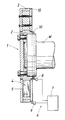
- a drive system indicated only with the free end of a crankshaft W comprises a torsional vibration damper 1, which consists of an inner part 2 which is flange-mounted on the crankshaft W in a rotationally fixed manner and an outer part 3 which is rotatably mounted relative to the inner part.
- Spring elements 4 are clamped between the inner and outer parts 2, 3 for torque transmission, with oil filled into the chambers 5 formed between the inner and outer parts 2, 3 and spring elements 4 due to its displacement when the inner and outer parts 2, 3 and the associated spring element deflection gives the desired damping.
- a monitoring device 6 which has a computer 7 and at least two sensors 8, 9.
- the transducers 8, 9, which are designed as inductive or optoelectrical transmitters, are each assigned to the inner part 2 and the outer part 3 and act to determine the absolute rotation of the associated part with an only indicated ring of recesses 10, for example bores arranged along a circle, tooth gaps of a gear wheel or the like, or together with a wreath-like line pattern.
- the monitoring device 6 therefore makes it possible, in a simple, rational and safe manner, to continuously monitor a drive system for state variables caused by torsional vibrations, so that overloading of the drive parts is not to be feared and the prerequisites for complying with the expected lifetimes can be created.
Landscapes
- Physics & Mathematics (AREA)
- General Physics & Mathematics (AREA)
- Measurement Of Mechanical Vibrations Or Ultrasonic Waves (AREA)
- Testing Of Devices, Machine Parts, Or Other Structures Thereof (AREA)
- Force Measurement Appropriate To Specific Purposes (AREA)
Applications Claiming Priority (2)
| Application Number | Priority Date | Filing Date | Title |
|---|---|---|---|
| AT0193490A AT396633B (de) | 1990-09-25 | 1990-09-25 | Überwachungseinrichtung zur überwachung drehschwingungsbedingter zustandsgrössen einer antriebsanlage |
| AT1934/90 | 1990-09-25 |
Publications (2)
| Publication Number | Publication Date |
|---|---|
| EP0478529A2 true EP0478529A2 (fr) | 1992-04-01 |
| EP0478529A3 EP0478529A3 (en) | 1993-03-03 |
Family
ID=3524184
Family Applications (1)
| Application Number | Title | Priority Date | Filing Date |
|---|---|---|---|
| EP19910890182 Withdrawn EP0478529A3 (en) | 1990-09-25 | 1991-08-16 | Arrangement for the control of condition parameters of a drive determined by torsional vibrations |
Country Status (4)
| Country | Link |
|---|---|
| EP (1) | EP0478529A3 (fr) |
| JP (1) | JPH04273032A (fr) |
| KR (1) | KR920006731A (fr) |
| AT (1) | AT396633B (fr) |
Cited By (3)
| Publication number | Priority date | Publication date | Assignee | Title |
|---|---|---|---|---|
| EP2143973A1 (fr) | 2008-07-11 | 2010-01-13 | KNORR-BREMSE SYSTEME FÜR NUTZFAHRZEUGE GmbH | Système de surveillance et procédé pour surveiller des amortisseurs de torsion |
| WO2016164952A1 (fr) * | 2015-04-14 | 2016-10-20 | Kristl, Seibt & Co. Gesellschaft M.B.H. | Procédé et dispositif de surveillance d'une liaison d'arbre pourvue d'un élément d'amortissement |
| EP3779234A1 (fr) | 2019-08-13 | 2021-02-17 | Liebherr Machines Bulle SA | Procédé de surveillance d'un amortisseur de vibrations torsionnelles |
Families Citing this family (3)
| Publication number | Priority date | Publication date | Assignee | Title |
|---|---|---|---|---|
| AT502432B1 (de) * | 2005-05-17 | 2008-04-15 | Geislinger Gmbh | Verfahren zum überprüfen eines drehschwingungsdämpfers |
| EP3093641B1 (fr) * | 2015-05-11 | 2017-06-28 | Siemens Aktiengesellschaft | Procédé de détermination d'une force de traction axiale appliquée à un composant |
| KR102481336B1 (ko) * | 2015-06-15 | 2022-12-26 | 현대두산인프라코어(주) | 플라이휠 |
Citations (7)
| Publication number | Priority date | Publication date | Assignee | Title |
|---|---|---|---|---|
| US3125983A (en) * | 1964-03-24 | Torsional vibration alarm | ||
| US3577802A (en) * | 1969-03-07 | 1971-05-04 | Houdaille Industries Inc | Leaf spring tuned viscous vibration damper |
| US4148222A (en) * | 1977-12-22 | 1979-04-10 | General Electric Company | Apparatus and method for measuring torsional vibration |
| GB1570534A (en) * | 1977-01-26 | 1980-07-02 | Wallace Murray Corp | Measurement of torsional vibration |
| US4592241A (en) * | 1982-09-08 | 1986-06-03 | Nippon Soken | Torque detector |
| EP0191560A2 (fr) * | 1985-02-02 | 1986-08-20 | LUCAS INDUSTRIES public limited company | Dispositif de surveillance du couple de rotation |
| US4808817A (en) * | 1987-11-23 | 1989-02-28 | Sundstrand Corporation | Rotational acceleration detector with microdot coding |
Family Cites Families (1)
| Publication number | Priority date | Publication date | Assignee | Title |
|---|---|---|---|---|
| DE3112714C1 (de) * | 1981-03-31 | 1982-11-11 | Jean Walterscheid Gmbh, 5204 Lohmar | Vorrichtung zum Messen und UEberwachen des Antriebes an einem landwirtschaftlichen Anbau- oder Anhaengegeraet |
-
1990
- 1990-09-25 AT AT0193490A patent/AT396633B/de not_active IP Right Cessation
-
1991
- 1991-08-16 EP EP19910890182 patent/EP0478529A3/de not_active Withdrawn
- 1991-09-06 JP JP3303720A patent/JPH04273032A/ja active Pending
- 1991-09-18 KR KR1019910016254A patent/KR920006731A/ko not_active Application Discontinuation
Patent Citations (7)
| Publication number | Priority date | Publication date | Assignee | Title |
|---|---|---|---|---|
| US3125983A (en) * | 1964-03-24 | Torsional vibration alarm | ||
| US3577802A (en) * | 1969-03-07 | 1971-05-04 | Houdaille Industries Inc | Leaf spring tuned viscous vibration damper |
| GB1570534A (en) * | 1977-01-26 | 1980-07-02 | Wallace Murray Corp | Measurement of torsional vibration |
| US4148222A (en) * | 1977-12-22 | 1979-04-10 | General Electric Company | Apparatus and method for measuring torsional vibration |
| US4592241A (en) * | 1982-09-08 | 1986-06-03 | Nippon Soken | Torque detector |
| EP0191560A2 (fr) * | 1985-02-02 | 1986-08-20 | LUCAS INDUSTRIES public limited company | Dispositif de surveillance du couple de rotation |
| US4808817A (en) * | 1987-11-23 | 1989-02-28 | Sundstrand Corporation | Rotational acceleration detector with microdot coding |
Cited By (3)
| Publication number | Priority date | Publication date | Assignee | Title |
|---|---|---|---|---|
| EP2143973A1 (fr) | 2008-07-11 | 2010-01-13 | KNORR-BREMSE SYSTEME FÜR NUTZFAHRZEUGE GmbH | Système de surveillance et procédé pour surveiller des amortisseurs de torsion |
| WO2016164952A1 (fr) * | 2015-04-14 | 2016-10-20 | Kristl, Seibt & Co. Gesellschaft M.B.H. | Procédé et dispositif de surveillance d'une liaison d'arbre pourvue d'un élément d'amortissement |
| EP3779234A1 (fr) | 2019-08-13 | 2021-02-17 | Liebherr Machines Bulle SA | Procédé de surveillance d'un amortisseur de vibrations torsionnelles |
Also Published As
| Publication number | Publication date |
|---|---|
| JPH04273032A (ja) | 1992-09-29 |
| ATA193490A (de) | 1991-08-15 |
| EP0478529A3 (en) | 1993-03-03 |
| KR920006731A (ko) | 1992-04-28 |
| AT396633B (de) | 1993-10-25 |
Similar Documents
| Publication | Publication Date | Title |
|---|---|---|
| EP2115412B1 (fr) | Procédé et dispositif pour surveiller une chaîne cinématique présentant un accouplement très élastique | |
| EP0347764B1 (fr) | Dispositif pour mesurer le moment de torsion d'une armature mobile par un vérin | |
| EP3766646B1 (fr) | Train d'engrenage de type roue cycloïdale pourvu de dispositif de détection de couple | |
| DE2935406A1 (de) | Messvorrichtung | |
| DE2709569A1 (de) | Zentrifuge mit einer einrichtung zum aufspueren und anzeigen von torsionsschwingungen | |
| CH643092A5 (de) | Vorrichtung zum messen des von einem elektromotor ausgeuebten drehmomentes. | |
| EP3963303B1 (fr) | Procédé de surveillance d'un entraînement par courroie | |
| AT396633B (de) | Überwachungseinrichtung zur überwachung drehschwingungsbedingter zustandsgrössen einer antriebsanlage | |
| EP3833514B1 (fr) | Bras de robot muni d'au moins un capteur de couple d'articulation | |
| DE602004008745T2 (de) | Förderbandantrieb und betriebsverfahren | |
| EP1931890B1 (fr) | Systeme de controle de duree de vie | |
| DE102018126698B4 (de) | Riemenaustausch-Ermittlungsvorrichtung und Austauschermittlungsverfahren | |
| EP0634007B1 (fr) | Dispositif pour mesurer le couple dans un engrenage afin de transmettre un mouvement rotatif | |
| DE102016116391B3 (de) | Verfahren zum Überwachen einer Schneckenzentrifuge | |
| DE2811809C2 (de) | Meßumformer zum Messen von Verdrehwinkeln zwischen zwei Meßstellen eines ein Drehmoment übertragenden Maschinenelementes | |
| DE19835334C2 (de) | Antriebsstrang für ein unter Tage eingesetztes Betriebsmittel mit umlaufendem Kettenstrang | |
| EP0053357A1 (fr) | Dispositif pour mesurer le couple de torsion | |
| DE2637954B2 (de) | Schraubmaschine für Schienenbefestigungsschrauben | |
| DE102022003812B4 (de) | Eine Stoßbelastungs-Drehmomentschutzeinrichtung mit elektrischer Steuerfunktion | |
| DE10210148A1 (de) | Drehmomentmeßvorrichtung und Hilfskraftlenkung für ein Kraftfahrzeug | |
| DE102017106311A1 (de) | Wechselflansch mit Sensorik für ein Getriebe | |
| DE3150324A1 (de) | Anordnung zum erfassen der materialermuedung eines festen koerpers | |
| DE2147974A1 (de) | Drehmoment-aufnehmer | |
| EP3032233A1 (fr) | Dispositif de détermination de couple et entraînement destiné à actionner un élément de machine | |
| DE102017200569B4 (de) | Messanordnung zum Erfassen einer Drehmomentbelastung |
Legal Events
| Date | Code | Title | Description |
|---|---|---|---|
| PUAI | Public reference made under article 153(3) epc to a published international application that has entered the european phase |
Free format text: ORIGINAL CODE: 0009012 |
|
| AK | Designated contracting states |
Kind code of ref document: A2 Designated state(s): BE CH DE DK ES FR GB GR IT LI LU NL SE |
|
| PUAL | Search report despatched |
Free format text: ORIGINAL CODE: 0009013 |
|
| AK | Designated contracting states |
Kind code of ref document: A3 Designated state(s): BE CH DE DK ES FR GB GR IT LI LU NL SE |
|
| STAA | Information on the status of an ep patent application or granted ep patent |
Free format text: STATUS: THE APPLICATION IS DEEMED TO BE WITHDRAWN |
|
| 18D | Application deemed to be withdrawn |
Effective date: 19930906 |