EP0478468B1 - Regenerative centrifugal compressor - Google Patents
Regenerative centrifugal compressor Download PDFInfo
- Publication number
- EP0478468B1 EP0478468B1 EP91420303A EP91420303A EP0478468B1 EP 0478468 B1 EP0478468 B1 EP 0478468B1 EP 91420303 A EP91420303 A EP 91420303A EP 91420303 A EP91420303 A EP 91420303A EP 0478468 B1 EP0478468 B1 EP 0478468B1
- Authority
- EP
- European Patent Office
- Prior art keywords
- blades
- inlet
- regenerative
- compressor
- generally
- Prior art date
- Legal status (The legal status is an assumption and is not a legal conclusion. Google has not performed a legal analysis and makes no representation as to the accuracy of the status listed.)
- Expired - Lifetime
Links
- 230000001172 regenerating effect Effects 0.000 title claims description 24
- 230000006835 compression Effects 0.000 claims description 31
- 238000007906 compression Methods 0.000 claims description 31
- 229920001343 polytetrafluoroethylene Polymers 0.000 claims description 4
- 239000004810 polytetrafluoroethylene Substances 0.000 claims description 4
- 229920003002 synthetic resin Polymers 0.000 claims description 4
- 239000000057 synthetic resin Substances 0.000 claims description 4
- 239000000463 material Substances 0.000 claims description 3
- 239000002783 friction material Substances 0.000 claims description 2
- 230000037361 pathway Effects 0.000 claims description 2
- 238000007789 sealing Methods 0.000 claims 2
- 239000007789 gas Substances 0.000 description 10
- 239000004809 Teflon Substances 0.000 description 3
- 229920006362 Teflon® Polymers 0.000 description 3
- XKRFYHLGVUSROY-UHFFFAOYSA-N Argon Chemical compound [Ar] XKRFYHLGVUSROY-UHFFFAOYSA-N 0.000 description 2
- 239000012530 fluid Substances 0.000 description 2
- VNWKTOKETHGBQD-UHFFFAOYSA-N methane Chemical compound C VNWKTOKETHGBQD-UHFFFAOYSA-N 0.000 description 2
- XAGFODPZIPBFFR-UHFFFAOYSA-N aluminium Chemical compound [Al] XAGFODPZIPBFFR-UHFFFAOYSA-N 0.000 description 1
- 229910052782 aluminium Inorganic materials 0.000 description 1
- 229910052786 argon Inorganic materials 0.000 description 1
- 230000000694 effects Effects 0.000 description 1
- 239000007788 liquid Substances 0.000 description 1
- 238000012423 maintenance Methods 0.000 description 1
- 238000012986 modification Methods 0.000 description 1
- 230000004048 modification Effects 0.000 description 1
- 239000003345 natural gas Substances 0.000 description 1
- 230000002093 peripheral effect Effects 0.000 description 1
- -1 polytetrafluoroethylene Polymers 0.000 description 1
- 238000005086 pumping Methods 0.000 description 1
- 239000007787 solid Substances 0.000 description 1
Images




Classifications
-
- F—MECHANICAL ENGINEERING; LIGHTING; HEATING; WEAPONS; BLASTING
- F04—POSITIVE - DISPLACEMENT MACHINES FOR LIQUIDS; PUMPS FOR LIQUIDS OR ELASTIC FLUIDS
- F04D—NON-POSITIVE-DISPLACEMENT PUMPS
- F04D17/00—Radial-flow pumps, e.g. centrifugal pumps; Helico-centrifugal pumps
- F04D17/08—Centrifugal pumps
- F04D17/10—Centrifugal pumps for compressing or evacuating
- F04D17/12—Multi-stage pumps
-
- F—MECHANICAL ENGINEERING; LIGHTING; HEATING; WEAPONS; BLASTING
- F04—POSITIVE - DISPLACEMENT MACHINES FOR LIQUIDS; PUMPS FOR LIQUIDS OR ELASTIC FLUIDS
- F04D—NON-POSITIVE-DISPLACEMENT PUMPS
- F04D29/00—Details, component parts, or accessories
- F04D29/08—Sealings
- F04D29/16—Sealings between pressure and suction sides
- F04D29/161—Sealings between pressure and suction sides especially adapted for elastic fluid pumps
-
- F—MECHANICAL ENGINEERING; LIGHTING; HEATING; WEAPONS; BLASTING
- F04—POSITIVE - DISPLACEMENT MACHINES FOR LIQUIDS; PUMPS FOR LIQUIDS OR ELASTIC FLUIDS
- F04D—NON-POSITIVE-DISPLACEMENT PUMPS
- F04D23/00—Other rotary non-positive-displacement pumps
- F04D23/008—Regenerative pumps
Definitions
- This invention is directed to regenerative centrifugal pumps or blowers, and is more particularly concerned with improved regenerative devices having greater efficiency and power.
- Regenerative compressors are rotor-dynamic fluid handling machines that, with a single bladded impeller disk, achieve a compression ratio that is the equivalent of several centrifugal stages having the same blade tip speed.
- the impeller disk can have a set of blades or vanes projecting axially at one or both sides of the disk rim.
- a housing encases the impeller disk and defines annular compression chambers between an inlet port and an outlet or discharge port.
- a stripper seal is provided between the outlet port and the inlet port. This stripper seal achieves a close clearance over the blades so that only the gas present between the vanes passes from the outlet port back into the inlet port end of the compression chamber.
- Each annular compression chamber has a cross section that is more or less circular, and a solid core can be provided at the tip of the vanes or blades.
- the blades drive gasses in the chamber radially outward, and the gasses are guided by the core and the chamber walls back to the radially inward or intake edge of the impeller blades, which then again propel the gases outwards.
- the gasses follow a generally helical path encountering the impeller blades several times in the course of their journey through the compression chamber.
- Each passage through the vanes or blades compresses the gasses, and is the equivalent of a single stage of conventional centrifugal compression (see for example US-A-4 279 570 FR-A-2 305 619).
- the compressor has an impeller or rotor disk that is rotationally supported in a housing.
- the housing defines a pair of annular compression chambers, with the two rows of blades each travelling through a respective one of the compression chambers.
- the housing has an air or gas inlet port and an exhaust or outlet port, with the compression chambers extending from the inlet port to the outlet port in the rotation direction of the impeller disk.
- inlet baffles guide the intake air (or other gas) around the blades and compression chamber to enter the chamber at the low pressure, i.e. radially inward, side of the impeller blades.
- the compression chambers are generally round in cross section, and each includes an annular core that extends within the compression chamber alongside the axial tips of the impeller blades to define a torsional pathway for the gasses discharged from the blades.
- Each core extends from the inlet port, where its end is integrally formed with the inlet baffle, to the outlet port.
- the core favorably is of generally D-shaped cross section.
- the stripper seal extends from the outlet port to the inlet port in the rotation direction of the impeller.
- the stripper seal has an open passage of substantially the same cross section as the impeller blade profile. Compressed gasses in the compression chamber are stripped from the impeller blades and blocked from flowing from the outlet around the blades to the inlet.
- the stripper seal includes respective channel member inserts formed of Teflon (i.e. PTFE) or another low-friction synthetic resin that is softer than the material (e.g. aluminum) of the impeller blades. The inserts fit into respective receptacles at the stripper region of the housing, i.e. between the outlet and inlet ports.
- the stripper inserts are preferably in the form of an arcuate channel with a web portion that secures to the housing receptacles and inner and outer coaxial circumferential flanges disposed respectively at the intake and discharge edges of the impeller blades.
- the inner flange is of a greater circumferential extent than the outer flange, so that the spaces between successive impeller blades are closed off at their intake side before being closed off at their discharge side when the blades encounter the stripper seal. Also, the spaces open first at the outer or discharge side when the blades leave the stripper seal and enter the inlet region. This reduces the turbulence from compressed gasses that are carried in the spaces between blades from the outlet to the inlet regions.
- the blades are configured as forward sloping, with an L-shaped profile having a round inner or intake edge, a generally straight lead-in portion, an arcuate bend, a generally straight exit portion, and a flat, narrow discharge outer edge. Successive blades define between them spaces that are each of generally constant width from the intake edges to the arcuate bends, and then open gradually from the arcuate bends to the discharge edges.
- the two rows of blades are preferably staggered, so that blades on one side of the impeller disk are aligned with the spaces between blades on the other side of the disk.
- Running seals i.e. annular rings of Teflon or the like, can be disposed between the radially inward portion of the housing and a facing generally cylindrical surface of the rim of the impeller disk. These seals help contain compressed gasses in the compression chambers.
- the regenerative compressor of this invention is quieter and more reliable than previous designs, and achieves a greater pressure ratio at improved efficiency. If the stripper seals become damaged, they can be easily replaced.
- Figs. 1 and 2 are left and right side elevations of a regenerative centrifugal compressor according to one preferred embodiment of this invention.
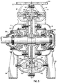
- Fig. 3 is a sectional elevation taken at 3-3 of Fig. 2.
- Fig. 4 is a top plan view of the compressor of this embodiment, taken at 4 - 4 of Fig. 2.
- Fig. 5 is a partial sectional view taken at 5 - 5 of Fig. 4.
- Fig. 6 illustrates an alternative shaft seal arrangement for a portion of the embodiment illustrated in Fig. 3.
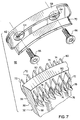
- Fig. 7 is a partial assembly view of the impeller and stripper seal of the preferred embodiment of this invention.
- Fig. 8 is a partial elevational view of the preferred embodiment.
- Fig. 9A to 9I are cross sectional views of one of the compression chambers, taken at 9A to 9I of Fig. 8, respectively.
- a compressor assembly 10 ⁇ is shown to comprise a right housing half 12 and a left housing half 14.
- An impeller drive shaft 16 extends out a bearing support in the housing half 12.
- the motor (not shown) is attached to the shaft 16 at the right housing half 12 as shown in Fig. 1.
- the direction of rotation of the impeller shaft 16 is as indicated by an arrow, which can be embossed or molded on the housing.
- An inner port 18 and an outer port 20 ⁇ are provided at an upper part of the compressor assembly 10 ⁇ .
- a generally toroidal compression chamber 22 is formed in each half 12, 14 of the compressor housing, and each chamber 22 extends in the rotation direction from the inlet port 18 to the outlet port 20 ⁇ .
- a stripper portion 24 then continues in the rotation direction the short distance from the outlet port to the inlet port.
- Stands or feet 26 are attached onto the compressor assembly and serve for mounting the same.
- the inlet port 18 has a J-shaped cross section, and inlet air is carried from the mouth of the inlet port 18 around to an underside or radially inward portion of the compression chamber 22 at the inlet port.
- shaft seal 28 which can be of labyrinth seal design, to seal the housing half 12 about the shaft 16.
- Bearings 30 ⁇ of known design can support the shaft 16 rotationally.
- an impeller disk 32 having a hub 34 that is mounted on the shaft, and a peripheral rim 36.
- the rim has a cylindrical surface 38 that faces radially inwards on either axial side of the disk 32.
- a low-friction ring-type running seal 40 ⁇ is provided on an inner cylindrical face 42 of each housing half 12, 14 that faces a respective cylindrical surface 38. The seals 40 ⁇ block the escape of high pressure gasses from the compression chamber 22 into a low-pressure enclosed area 44 between the hub 34 and the rim 36 of the impeller.
- outer running seals can be provided between outer cylindrical surfaces of the rim 36 and facing surfaces of the housing halves 12, 14.
- Stripper seals 48 are provided in the form of inserts of a low- friction material that is softer than the rotor blades. The stripper seals are attached into receptacles 50 ⁇ in the stripper area 24, with one such stripper seal 48 being attached into each one of the housing halves 12, 14.
- each of the chambers 22 has a generally annular core 52 at the center of the chamber adjacent the axial tips of the impeller blades.
- the cores are of a generally D-shaped cross section.
- the cores have a straight or generally flat surface adjacent the blades and a generally round or torsional surface that, together with the inside of the chamber 22, defines a circular path of air discharged from the radially outward side of the blades back to the radially inwards side thereof.
- the inlet and outlet ports 18, 20 ⁇ have flanges 54, 56, respectively, to which pneumatic tubing or piping can be connected.
- a baffle 58 is provided in the inlet port, the baffle 58 extending into each housing half 12, 14, to carry intake air out around the rows 46 of impeller blades to the radial underside of the chamber 22, i.e., to the intake side of the impeller blades.
- a gas seal 60 ⁇ can be employed in lieu of a labyrinth type seal, if the compressor assembly 10 ⁇ is used for a gas other than air, for example, argon, natural gas, or the like, to prevent gas from escaping out along the drive shaft 16.
- a gas other than air for example, argon, natural gas, or the like
- the stripper seal 48 is in the form of an arcuate channel-shaped member having a flat web portion 62 with countersunk screw holes 64, through which machine screws 66 can fasten the stripper seal 48 into the receptacle 50 ⁇ that is provided for it.
- the stripper seal 48 has a radially outer flange 68 that is generally cylindrical and extends in the circumferential direction between the outlet port and the inlet port.
- a generally cylindrical inner flange 70 ⁇ , which is co-axial with the outer flange 68, has a greater circumferential extent, both at the inlet side and at the outlet side.
- the stripper seal 48 is made of a softer material than the blades of the impeller, so that the fit between the impeller blades 46 and the stripper seal 48 can be as close as possible, without significant risk of damage to the blades.
- the stripper seal 48 can be molded or machined of Teflon (polytetrafluoroethylene) or another suitable synthetic resin with low friction characteristics.
- each impeller blade row 46 is formed of a succession of blades 72 and spaces 74 between the blades.
- Each of the blades 72 has a generally L-shaped profile, with a rounded intake edge 76 at its radially inward side, a straight portion leading to a generally arcuate bend 78 at its mid portion, and a generally straight exit portion leading to a flat, narrow discharge edge 80 ⁇ at its radially outward side.
- the blades 72 are positioned alternately, i.e. staggered, so that the blades 72 on each side of the impeller rim 36 are at the locations of spaces 74 between blades on the other side of the rim 36.
- the successive blades then define between them the spaces 74 that are of generally constant width from the intake edges 76 to the bends 78, and then open gradually to the arcuate bends 78 to the discharge edges 80 ⁇ .
- Fig. 8 shows details of the position of the stripper 48 and the chamber 22 at the inlet and outlet ports 18, 20 ⁇ .
- Figs. 9A - 9I are sections of the chamber for one side only of the housing, taken along the planes indicated in Fig. 8.
- Figs. 9A and 9B show the general configuration of the baffle 58, which defines the J-shaped cross section for the air inlet so that it opens onto the intake edge 76 of the impeller blades 72.
- the baffle 58 begins to assume a D-shaped section and this becomes the annular core 52, which is supported at one or more points by posts 82.
- the chamber has the cross section as generally shown in Fig. 9E.
- Figs. 9F, 9G, 9H, 9I show the cross section of the chamber 22 at the outlet port 20 ⁇ , as the impeller nears the stripper area 24, where the impeller blades 72 pass through the stripper seal 48.
- the radially outward part of the chamber 22 begins to open outward while the radially inward part of the chamber 22 becomes sealed off and joins with the stripper area.
- the longer lower or inner flange 70 ⁇ of the stripper seal 48 is encountered first. This serves to cut off the intake edges of the spaces 74 between the blades prior to closure of the discharge edges thereof. This feature permits a pressure between the blades to be reduced somewhat at the stripper seals to reduce noise and increase efficiency.
- the stripper seal 48 occupies all the area that is not required for the impeller 32.
- the stripper seal thus blocks the flow of high pressure gas from the outlet port 20 ⁇ to the inlet port 18.
Landscapes
- Engineering & Computer Science (AREA)
- Mechanical Engineering (AREA)
- General Engineering & Computer Science (AREA)
- Structures Of Non-Positive Displacement Pumps (AREA)
Description
- This invention is directed to regenerative centrifugal pumps or blowers, and is more particularly concerned with improved regenerative devices having greater efficiency and power.
- Regenerative compressors are rotor-dynamic fluid handling machines that, with a single bladded impeller disk, achieve a compression ratio that is the equivalent of several centrifugal stages having the same blade tip speed. The impeller disk can have a set of blades or vanes projecting axially at one or both sides of the disk rim. A housing encases the impeller disk and defines annular compression chambers between an inlet port and an outlet or discharge port. A stripper seal is provided between the outlet port and the inlet port. This stripper seal achieves a close clearance over the blades so that only the gas present between the vanes passes from the outlet port back into the inlet port end of the compression chamber.
- Each annular compression chamber has a cross section that is more or less circular, and a solid core can be provided at the tip of the vanes or blades. The blades drive gasses in the chamber radially outward, and the gasses are guided by the core and the chamber walls back to the radially inward or intake edge of the impeller blades, which then again propel the gases outwards. The gasses follow a generally helical path encountering the impeller blades several times in the course of their journey through the compression chamber. Each passage through the vanes or blades compresses the gasses, and is the equivalent of a single stage of conventional centrifugal compression (see for example US-A-4 279 570 FR-A-2 305 619).
- However, these machines have had limited applicability because of limited efficiency and tendency to dissipate power. Generally, regenerative centrifugal compressors have an isothermic efficiency of fifty percent or less. A great deal of turbulence is created in the compression chamber because gas is ejected into gasses already in the chamber. In FR-A-2 305 619, it has been proposed in order to reduce the turbulence to put a diverter at the inlet of the compression chamber. Unfortunately, the diverter does not provide a limitation of the turbulence, due to the absence of any annular core extending within said compression chamber and adjacent the axial tips of the blades.
- Other apparatus such as described in WO 89/06318 have been proposed in order to improve the adiabatic efficiency. To that effect, a baffle plate is positionned between the compression chamber and the inlet. However, the inlet of this compressor extends axially, thus limitating said compressor to having blades only on one side of the rotor. In addition, this plate does not efficiently reduce or avoid the turbulence.
- Other types of compressors are known from US-A-2 306 951 and DE-A-1 817 430 wherin the inlet is axially oriented.
- Also, previous designs for stripper seals have been unable to avoid problems of leakage and noise, and require a relatively large clearance for the impeller blades.
- On the other hand, these compressors are often preferable to the more efficient reciprocal compressors, especially in applications that require high reliability and which must be relatively free of operation or maintenance problems. Pumps of this type have also been employed for pumping liquids.
- It is an object of this invention to provide a regenerative centrifugal pump or blower which has improved efficiency.
- It is another object to provide a regenerative centrifugal compressor with improved compression characteristics and reduced leakage characteristics.
- It is a further object of this invention to provide a regenerative centrifugal compressor with a more effective, serviceable stripper seal.
- According to an aspect of the present invention, the compressor has an impeller or rotor disk that is rotationally supported in a housing. There are two rows of axial impeller blades at the rim of the rotor disk, and the housing defines a pair of annular compression chambers, with the two rows of blades each travelling through a respective one of the compression chambers. The housing has an air or gas inlet port and an exhaust or outlet port, with the compression chambers extending from the inlet port to the outlet port in the rotation direction of the impeller disk. At the inlet port, inlet baffles guide the intake air (or other gas) around the blades and compression chamber to enter the chamber at the low pressure, i.e. radially inward, side of the impeller blades.
- The compression chambers are generally round in cross section, and each includes an annular core that extends within the compression chamber alongside the axial tips of the impeller blades to define a torsional pathway for the gasses discharged from the blades. Each core extends from the inlet port, where its end is integrally formed with the inlet baffle, to the outlet port. The core favorably is of generally D-shaped cross section.
- The stripper seal extends from the outlet port to the inlet port in the rotation direction of the impeller. The stripper seal has an open passage of substantially the same cross section as the impeller blade profile. Compressed gasses in the compression chamber are stripped from the impeller blades and blocked from flowing from the outlet around the blades to the inlet. In the preferred embodiment the stripper seal includes respective channel member inserts formed of Teflon (i.e. PTFE) or another low-friction synthetic resin that is softer than the material (e.g. aluminum) of the impeller blades. The inserts fit into respective receptacles at the stripper region of the housing, i.e. between the outlet and inlet ports.
- The stripper inserts are preferably in the form of an arcuate channel with a web portion that secures to the housing receptacles and inner and outer coaxial circumferential flanges disposed respectively at the intake and discharge edges of the impeller blades. The inner flange is of a greater circumferential extent than the outer flange, so that the spaces between successive impeller blades are closed off at their intake side before being closed off at their discharge side when the blades encounter the stripper seal. Also, the spaces open first at the outer or discharge side when the blades leave the stripper seal and enter the inlet region. This reduces the turbulence from compressed gasses that are carried in the spaces between blades from the outlet to the inlet regions.
- For improved fluid dynamics, the blades are configured as forward sloping, with an L-shaped profile having a round inner or intake edge, a generally straight lead-in portion, an arcuate bend, a generally straight exit portion, and a flat, narrow discharge outer edge. Successive blades define between them spaces that are each of generally constant width from the intake edges to the arcuate bends, and then open gradually from the arcuate bends to the discharge edges. The two rows of blades are preferably staggered, so that blades on one side of the impeller disk are aligned with the spaces between blades on the other side of the disk.
- Running seals, i.e. annular rings of Teflon or the like, can be disposed between the radially inward portion of the housing and a facing generally cylindrical surface of the rim of the impeller disk. These seals help contain compressed gasses in the compression chambers.
- The regenerative compressor of this invention, with its inventive improvements, is quieter and more reliable than previous designs, and achieves a greater pressure ratio at improved efficiency. If the stripper seals become damaged, they can be easily replaced.
- The above and many other objects, features, and advantages of this invention will become apparent to those skilled in the art from the ensuing description of a preferred embodiment, which should be read in conjunction with the accompanying Drawing.
- Figs. 1 and 2 are left and right side elevations of a regenerative centrifugal compressor according to one preferred embodiment of this invention.
- Fig. 3 is a sectional elevation taken at 3-3 of Fig. 2.
- Fig. 4 is a top plan view of the compressor of this embodiment, taken at 4 - 4 of Fig. 2.
- Fig. 5 is a partial sectional view taken at 5 - 5 of Fig. 4.
- Fig. 6 illustrates an alternative shaft seal arrangement for a portion of the embodiment illustrated in Fig. 3.
- Fig. 7 is a partial assembly view of the impeller and stripper seal of the preferred embodiment of this invention.
- Fig. 8 is a partial elevational view of the preferred embodiment.
- Fig. 9A to 9I are cross sectional views of one of the compression chambers, taken at 9A to 9I of Fig. 8, respectively.
- With reference to the Drawing, and initially to Figs. 1 and 2, a compressor assembly 10̸ is shown to comprise a
right housing half 12 and aleft housing half 14. Animpeller drive shaft 16 extends out a bearing support in thehousing half 12. In this embodiment, the motor (not shown) is attached to theshaft 16 at theright housing half 12 as shown in Fig. 1. - The direction of rotation of the
impeller shaft 16 is as indicated by an arrow, which can be embossed or molded on the housing. - An
inner port 18 and an outer port 20̸ are provided at an upper part of the compressor assembly 10̸. A generallytoroidal compression chamber 22 is formed in eachhalf chamber 22 extends in the rotation direction from theinlet port 18 to the outlet port 20̸. Astripper portion 24 then continues in the rotation direction the short distance from the outlet port to the inlet port. Stands orfeet 26 are attached onto the compressor assembly and serve for mounting the same. - As shown in large detail in Fig. 3, the
inlet port 18 has a J-shaped cross section, and inlet air is carried from the mouth of theinlet port 18 around to an underside or radially inward portion of thecompression chamber 22 at the inlet port. - As also shown in Fig. 3, there is a
shaft seal 28, which can be of labyrinth seal design, to seal thehousing half 12 about theshaft 16. Bearings 30̸ of known design can support theshaft 16 rotationally. - Within the housing, and driven by the
shaft 16, is animpeller disk 32 having ahub 34 that is mounted on the shaft, and aperipheral rim 36. The rim has acylindrical surface 38 that faces radially inwards on either axial side of thedisk 32. A low-friction ring-type running seal 40̸ is provided on an innercylindrical face 42 of eachhousing half cylindrical surface 38. The seals 40̸ block the escape of high pressure gasses from thecompression chamber 22 into a low-pressureenclosed area 44 between thehub 34 and therim 36 of the impeller. If desired outer running seals can be provided between outer cylindrical surfaces of therim 36 and facing surfaces of thehousing halves - As shown here generally and in more detail later, on each axial face of the
impeller rim 36 there is arespective row 46 of rotor blades, which drive the air or other gasses centrifically outward into the compression chamber for centrifugal compression, as the gas travels from the inlet port to the outlet port. Stripper seals 48 are provided in the form of inserts of a low- friction material that is softer than the rotor blades. The stripper seals are attached into receptacles 50̸ in thestripper area 24, with onesuch stripper seal 48 being attached into each one of thehousing halves - As also shown in Fig. 3, each of the
chambers 22 has a generallyannular core 52 at the center of the chamber adjacent the axial tips of the impeller blades. Here, the cores are of a generally D-shaped cross section. The cores have a straight or generally flat surface adjacent the blades and a generally round or torsional surface that, together with the inside of thechamber 22, defines a circular path of air discharged from the radially outward side of the blades back to the radially inwards side thereof. - As shown in Figs. 4 and 5, the inlet and
outlet ports 18, 20̸ haveflanges baffle 58 is provided in the inlet port, thebaffle 58 extending into eachhousing half rows 46 of impeller blades to the radial underside of thechamber 22, i.e., to the intake side of the impeller blades. - As shown in Fig. 6, a gas seal 60̸ can be employed in lieu of a labyrinth type seal, if the compressor assembly 10̸ is used for a gas other than air, for example, argon, natural gas, or the like, to prevent gas from escaping out along the
drive shaft 16. - Details of the
impeller 32 and thestripper seal 48 can be explained with reference to Fig. 7. Thestripper seal 48, only one of which is shown here, is in the form of an arcuate channel-shaped member having aflat web portion 62 with countersunk screw holes 64, through whichmachine screws 66 can fasten thestripper seal 48 into the receptacle 50̸ that is provided for it. Thestripper seal 48 has a radiallyouter flange 68 that is generally cylindrical and extends in the circumferential direction between the outlet port and the inlet port. A generally cylindrical inner flange 70̸, which is co-axial with theouter flange 68, has a greater circumferential extent, both at the inlet side and at the outlet side. Thestripper seal 48 is made of a softer material than the blades of the impeller, so that the fit between theimpeller blades 46 and thestripper seal 48 can be as close as possible, without significant risk of damage to the blades. Thestripper seal 48 can be molded or machined of Teflon (polytetrafluoroethylene) or another suitable synthetic resin with low friction characteristics. - As also shown in Fig. 7, each
impeller blade row 46 is formed of a succession ofblades 72 andspaces 74 between the blades. Each of theblades 72 has a generally L-shaped profile, with arounded intake edge 76 at its radially inward side, a straight portion leading to a generallyarcuate bend 78 at its mid portion, and a generally straight exit portion leading to a flat, narrow discharge edge 80̸ at its radially outward side. As also shown in Fig. 7, in the preferred mode theblades 72 are positioned alternately, i.e. staggered, so that theblades 72 on each side of theimpeller rim 36 are at the locations ofspaces 74 between blades on the other side of therim 36. The successive blades then define between them thespaces 74 that are of generally constant width from the intake edges 76 to thebends 78, and then open gradually to the arcuate bends 78 to the discharge edges 80̸. - Fig. 8 shows details of the position of the
stripper 48 and thechamber 22 at the inlet andoutlet ports 18, 20̸. Figs. 9A - 9I are sections of the chamber for one side only of the housing, taken along the planes indicated in Fig. 8. - Figs. 9A and 9B show the general configuration of the
baffle 58, which defines the J-shaped cross section for the air inlet so that it opens onto theintake edge 76 of theimpeller blades 72. As shown in Figs. 9C and 9D, at the intake end of thechamber 22, thebaffle 58 begins to assume a D-shaped section and this becomes theannular core 52, which is supported at one or more points by posts 82. At positions significantly away from the inlet andoutlet ports 18 and 20̸, the chamber has the cross section as generally shown in Fig. 9E. - Figs. 9F, 9G, 9H, 9I show the cross section of the
chamber 22 at the outlet port 20̸, as the impeller nears thestripper area 24, where theimpeller blades 72 pass through thestripper seal 48. Here, as shown in Figs. 9F, 9G, and 9H, the radially outward part of thechamber 22 begins to open outward while the radially inward part of thechamber 22 becomes sealed off and joins with the stripper area. As shown in Fig. 9G the longer lower or inner flange 70̸ of thestripper seal 48 is encountered first. This serves to cut off the intake edges of thespaces 74 between the blades prior to closure of the discharge edges thereof. This feature permits a pressure between the blades to be reduced somewhat at the stripper seals to reduce noise and increase efficiency. - As shown in Fig. 9I the
stripper seal 48 occupies all the area that is not required for theimpeller 32. The stripper seal thus blocks the flow of high pressure gas from the outlet port 20̸ to theinlet port 18. - While this invention has been described in detail with respect to a preferred embodiment, it should be understood that the invention is not limited to that precise embodiment. Rather, many modifications and variations would present themselves to those skilled in the art without departing from the scope and spirit of this invention, as defined in the appended claims. spirit of this invention, as defined in the appended claims.
Claims (14)
- A regenerative centrifugal compressor in which a rotor (32) has an axis (34), a rim (36), and a row (46) of impeller blades (72) that extend axially from one side of the rim, said blades having a radially inward intake edge (76) and a radially outward discharge edge (80); a housing (12, 14) for said rotor has a gas inlet (18) and a compressed gas outlet (20) angularly spaced apart, a generally annular compression chamber (22) formed in said housing having a radial extent to envelop said impeller blades (72) and extending circumferentially from said gas inlet (18) to said gas outlet (20) in the rotation direction of said rotor, the housing including an annular core (52) extending within said compression chamber (22) adjacent said axial tips of said impeller blades (72) to define a toroidal pathway for gas that is impelled by said blades, the core extending generally from said inlet (18) to said outlet (20) in the rotational direction of the rotor to guide gas impelled by said blades (72) from the radially inner intake edges (76) to the radially outer discharge edges (80) of said impeller blades ; and a stripper seal (48) extends from said outlet (20) to said inlet (18) in the rotation direction of the rotor, said stripper seal having an open passage of substantially the same cross section as said blades to strip compressed gas in said compression chamber and block compressed gas from flowing from the outlet (20) to the inlet (18) ;
said gas inlet (18) and compressed gas outlet (20) being radially oriented, ; characterized in that :
an inlet baffle (58) is formed in said housing at said inlet for guiding inlet gas around said impeller blades (72) and said compression chamber (22) to enter the compression chamber only at a radially inward side thereof. - The regenerative compressor of claim 1, further characterized in that said inlet baffle (58) extends radially inward past the impeller blades (72) and said compression chamber (22).
- The regenerative compressor of claims 1 or 2 further characterized in that said inlet baffle (58) defines an inlet duct of generally J-shaped section.
- The regenerative compressor of claims 1 or 2 further characterized in that said inlet baffle (58) is integrally formed with said core (52) at an inlet end thereof.
- The regenerative compressor of claims 1 to 4 further characterized in that said stripper seal (48) is in the form of an arcuate channel having inner and outer coaxial circumferential flanges (70, 68) respectively adjacent the intake edges (76) and discharge edges (80) of the impeller blades (72), said inner circumferential flange (70) extending further into said inlet (18) than said outer circumferential flange so that spaces between the impeller blades open first at their discharge edges as said impeller blades enter the inlet from the stripper seal.
- The regenerative centrifugal compressor of any of the preceding claims, further characterized in that said stripper seal (48) is formed of a low-friction material softer than the material of said blades (72) and fitted into a receptacle (50) in the housing (12, 14) for the stripper seal.
- The regenerative compressor of claim 6 further characterized in that said stripper seal (48) is formed of a low-friction synthetic resin.
- The regenerative compressor of claim 7 further characterized in that said stripper seal is formed of PTFE.
- The regenerative centrifugal compressor of any of the preceding claims, and further characterized in that the housing (12, 14) has a circumferential surface facing an inner circumferential edge (38) of the rim (36) of said rotor (32) ; and a low friction seal ring (40) disposed on said housing circumferential surface to seal against said inner circumferential edge of said rotor rim (32).
- The regenerative compressor of claim 9 characterized in that said sealing ring (40) is a low friction synthetic resin.
- The regenerative compressor of claim 10 characterized in that said sealing ring (40) is PTFE.
- The regenerative compressor of any preceding claims, characterized in that said blades (72) have a generally L-shaped profile having in succession a rounded intake edge (76), a generally straight leading portion, an arcuate bend (78), a generally straight exit portion, and a flat narrow discharge edge (80).
- The regenerative compressor of claim 12, further characterized in that successive ones of said blades (72) define between them a space (74) that has a generally constant width from the intake edges to the arcuate bends (78), and then opens gradually from the arcuate bends to the discharge edges (80) of the blades.
- The regenerative compressor of any preceding claims, further characterized in that said annular core (52) has a generally D-shaped cross section with a generally flat side facing the axial tips of the respective impeller blades (72) and with a round outer guide surface to guide the gas impelled by said blades from the radially outer discharge edges (80) to the radially inner intake edges (76) thereof.
Applications Claiming Priority (2)
| Application Number | Priority Date | Filing Date | Title |
|---|---|---|---|
| US07/589,795 US5143511A (en) | 1990-09-28 | 1990-09-28 | Regenerative centrifugal compressor |
| US589795 | 1990-09-28 |
Publications (2)
| Publication Number | Publication Date |
|---|---|
| EP0478468A1 EP0478468A1 (en) | 1992-04-01 |
| EP0478468B1 true EP0478468B1 (en) | 1994-10-05 |
Family
ID=24359553
Family Applications (1)
| Application Number | Title | Priority Date | Filing Date |
|---|---|---|---|
| EP91420303A Expired - Lifetime EP0478468B1 (en) | 1990-09-28 | 1991-08-22 | Regenerative centrifugal compressor |
Country Status (6)
| Country | Link |
|---|---|
| US (1) | US5143511A (en) |
| EP (1) | EP0478468B1 (en) |
| JP (1) | JPH04262093A (en) |
| KR (1) | KR0137012B1 (en) |
| DE (1) | DE69104455T2 (en) |
| ES (1) | ES2064968T3 (en) |
Families Citing this family (19)
| Publication number | Priority date | Publication date | Assignee | Title |
|---|---|---|---|---|
| AU679933B2 (en) * | 1992-08-21 | 1997-07-17 | Orbital Engine Company (Australia) Proprietary Limited | Regenerative pump |
| RU2032836C1 (en) * | 1992-12-29 | 1995-04-10 | Владимир Николаевич Хмара | Vortex compressor |
| US5527149A (en) * | 1994-06-03 | 1996-06-18 | Coltec Industries Inc. | Extended range regenerative pump with modified impeller and/or housing |
| US6422808B1 (en) | 1994-06-03 | 2002-07-23 | Borgwarner Inc. | Regenerative pump having vanes and side channels particularly shaped to direct fluid flow |
| US5658126A (en) * | 1994-10-20 | 1997-08-19 | Siemens Aktiengesellschaft | Side channel compressor |
| US5618417A (en) * | 1995-07-19 | 1997-04-08 | Spindler; William E. | Water aeration system |
| US6019571A (en) * | 1995-09-13 | 2000-02-01 | Siemens Aktiengesellschaft | Side channel compressor |
| GB9609281D0 (en) * | 1996-05-03 | 1996-07-10 | Boc Group Plc | Improved vacuum pumps |
| DE19780570D2 (en) * | 1996-06-19 | 1999-05-27 | Eberspaecher J Gmbh & Co | Side channel blower, in particular for the combustion air supply in a parking heater of a motor vehicle |
| DE29613186U1 (en) * | 1996-07-30 | 1996-09-19 | Siemens AG, 80333 München | Side channel blower |
| CA2301415A1 (en) * | 1999-04-19 | 2000-10-19 | Capstone Turbine Corporation | Helical flow compressor/turbine permanent magnet motor/generator |
| US6167107A (en) * | 1999-07-16 | 2000-12-26 | Particle Measuring Systems, Inc. | Air pump for particle sensing using regenerative fan, and associated methods |
| JP2004060618A (en) * | 2002-07-31 | 2004-02-26 | Aisan Ind Co Ltd | Friction regenerative pump |
| US7033137B2 (en) * | 2004-03-19 | 2006-04-25 | Ametek, Inc. | Vortex blower having helmholtz resonators and a baffle assembly |
| CA2645646C (en) | 2006-03-14 | 2015-09-22 | John D. Pickard | Rotor assembly for a radial turbine |
| FR2988145B1 (en) * | 2012-03-14 | 2016-09-30 | Michel Chiaffi | ROTARY COMPRESSOR WITH AT LEAST ONE SIDE CHANNEL |
| US9303645B2 (en) * | 2012-03-23 | 2016-04-05 | Victori, Llc | Regenerative blower with a convoluted contactless impeller-to-housing seal assembly |
| DE102014224283A1 (en) * | 2014-11-27 | 2016-06-02 | Robert Bosch Gmbh | Compressor with a sealing channel |
| PL3199816T3 (en) * | 2016-01-29 | 2021-11-29 | Cattani S.P.A. | Side-channel blower/aspirator with an improved impeller |
Family Cites Families (28)
| Publication number | Priority date | Publication date | Assignee | Title |
|---|---|---|---|---|
| US1973669A (en) * | 1931-01-12 | 1934-09-11 | Spoor Willem Lodewijk Joost | Rotary pump |
| US2217211A (en) * | 1937-09-11 | 1940-10-08 | Roots Connersville Blower Corp | Rotary pump |
| US2305619A (en) * | 1938-07-14 | 1942-12-22 | Lummus Co | Refining of oils |
| US2306951A (en) * | 1939-07-01 | 1942-12-29 | Irving C Jennings | Pump |
| US2578780A (en) * | 1946-09-20 | 1951-12-18 | Fairbanks Morse & Co | Rotary pump seal |
| US3292899A (en) * | 1966-04-04 | 1966-12-20 | Garrett Corp | Energy transfer machine |
| US3545890A (en) * | 1967-12-29 | 1970-12-08 | Mechanical Tech Inc | Regenerative compressor |
| DE1925949A1 (en) * | 1969-05-20 | 1970-12-03 | Jemco Seals Inc | Leak retention for rotating machine parts |
| US3666276A (en) * | 1969-12-11 | 1972-05-30 | Dev Des Ind Modernes Soc Et | Device for the sealing of a rotatable shaft |
| JPS5065912A (en) * | 1973-10-17 | 1975-06-03 | ||
| US3936240A (en) * | 1974-03-25 | 1976-02-03 | General Electric Company | Centrifugal-vortex pump |
| US3915589A (en) * | 1974-03-29 | 1975-10-28 | Gast Manufacturing Corp | Convertible series/parallel regenerative blower |
| NL7502752A (en) * | 1974-05-29 | 1975-12-02 | Siemens Ag | RING COMPRESSOR. |
| FR2305619A1 (en) * | 1975-03-27 | 1976-10-22 | Rateau Sa | Peripherally bladed turbine - usable as a driving or a driven unit, allowing higher expansion/compression ratios |
| IT1057591B (en) * | 1975-03-27 | 1982-03-30 | Rateau Soc | PERIPHERAL MACHINE FOR FLUID |
| US4279570A (en) * | 1978-03-31 | 1981-07-21 | The Garrett Corporation | Energy transfer machine |
| ZA796107B (en) * | 1978-11-28 | 1980-10-29 | Compair Ind Ltd | Regenerative rotodynamic machines |
| US4325672A (en) * | 1978-12-15 | 1982-04-20 | The Utile Engineering Company Limited | Regenerative turbo machine |
| JPS5718497A (en) * | 1980-07-04 | 1982-01-30 | Matsushita Electric Ind Co Ltd | Eddy flow fan |
| JPS5724493A (en) * | 1980-07-21 | 1982-02-09 | Hitachi Ltd | Vortex flow blower |
| US4566700A (en) * | 1982-08-09 | 1986-01-28 | United Technologies Corporation | Abrasive/abradable gas path seal system |
| US4460185A (en) * | 1982-08-23 | 1984-07-17 | General Electric Company | Seal including a non-metallic abradable material |
| JPS60156997A (en) * | 1984-01-26 | 1985-08-17 | Nippon Denso Co Ltd | Centrifugal type blower fan |
| JPH073237B2 (en) * | 1986-10-20 | 1995-01-18 | 株式会社ユニシアジェックス | Turbin type fuel pump |
| JPS63147992A (en) * | 1986-12-09 | 1988-06-20 | Daikin Ind Ltd | Vortex type turbo machine |
| GB8730341D0 (en) * | 1987-12-31 | 1988-02-03 | Compair Reavell Ltd | Regenerative rotodynamic machines |
| JPH01267390A (en) * | 1988-04-18 | 1989-10-25 | Daikin Ind Ltd | Vortex vacuum pump |
| US4948344A (en) * | 1989-10-17 | 1990-08-14 | Sundstrand Corporation | Controlled vortex regenerative pump |
-
1990
- 1990-09-28 US US07/589,795 patent/US5143511A/en not_active Expired - Lifetime
-
1991
- 1991-08-08 KR KR1019910013681A patent/KR0137012B1/en not_active Expired - Fee Related
- 1991-08-22 EP EP91420303A patent/EP0478468B1/en not_active Expired - Lifetime
- 1991-08-22 DE DE69104455T patent/DE69104455T2/en not_active Expired - Fee Related
- 1991-08-22 ES ES91420303T patent/ES2064968T3/en not_active Expired - Lifetime
- 1991-09-26 JP JP3274768A patent/JPH04262093A/en active Pending
Also Published As
| Publication number | Publication date |
|---|---|
| DE69104455T2 (en) | 1995-02-09 |
| EP0478468A1 (en) | 1992-04-01 |
| ES2064968T3 (en) | 1995-02-01 |
| KR0137012B1 (en) | 1998-07-01 |
| KR920006655A (en) | 1992-04-27 |
| US5143511A (en) | 1992-09-01 |
| DE69104455D1 (en) | 1994-11-10 |
| JPH04262093A (en) | 1992-09-17 |
Similar Documents
| Publication | Publication Date | Title |
|---|---|---|
| EP0478468A1 (en) | Regenerative centrifugal compressor | |
| US5709528A (en) | Turbomolecular vacuum pumps with low susceptiblity to particulate buildup | |
| EP0011982B1 (en) | Regenerative rotodynamic machines | |
| US4940385A (en) | Rotary disc pump | |
| US4395197A (en) | Centrifugal fluid machine | |
| US5810557A (en) | Fan wheel for an inline centrifugal fan | |
| EP0805275B1 (en) | Vacuum pump | |
| US4355951A (en) | Full admission pitot pump | |
| EP0602007B1 (en) | Vacuum cleaner having an impeller and diffuser | |
| KR102239812B1 (en) | Turbo Compressor | |
| EP0446900B1 (en) | Mixed-flow compressor | |
| US3395649A (en) | Impeller construction | |
| EA012818B1 (en) | Rotor for rotary machine and a rotary machine | |
| GB2366333A (en) | Multi-stage/regenerative centrifugal compressor | |
| KR100732196B1 (en) | Square whirlwind rotor | |
| EP0346456A1 (en) | Regenerative rotodynamic machines | |
| KR102033355B1 (en) | Small Size Turbo Compressor | |
| CA2260998C (en) | Fan wheel for an inline centrifugal fan | |
| JPS6144000Y2 (en) | ||
| JPH01170795A (en) | Vortex turbo-machinery | |
| US3245611A (en) | Fluid mover | |
| RU2237824C1 (en) | Vacuum gas0rotary pump | |
| KR0136669B1 (en) | Axial Flow Centrifugal Fan Casing Structure | |
| KR200407691Y1 (en) | Square whirlwind rotor | |
| JPH01147196A (en) | Spiral vortex type turbo machine |
Legal Events
| Date | Code | Title | Description |
|---|---|---|---|
| PUAI | Public reference made under article 153(3) epc to a published international application that has entered the european phase |
Free format text: ORIGINAL CODE: 0009012 |
|
| AK | Designated contracting states |
Kind code of ref document: A1 Designated state(s): DE ES FR GB IT |
|
| 17P | Request for examination filed |
Effective date: 19920615 |
|
| 17Q | First examination report despatched |
Effective date: 19930809 |
|
| GRAA | (expected) grant |
Free format text: ORIGINAL CODE: 0009210 |
|
| AK | Designated contracting states |
Kind code of ref document: B1 Designated state(s): DE ES FR GB IT |
|
| ITF | It: translation for a ep patent filed | ||
| ET | Fr: translation filed | ||
| REF | Corresponds to: |
Ref document number: 69104455 Country of ref document: DE Date of ref document: 19941110 |
|
| REG | Reference to a national code |
Ref country code: ES Ref legal event code: FG2A Ref document number: 2064968 Country of ref document: ES Kind code of ref document: T3 |
|
| PLBE | No opposition filed within time limit |
Free format text: ORIGINAL CODE: 0009261 |
|
| STAA | Information on the status of an ep patent application or granted ep patent |
Free format text: STATUS: NO OPPOSITION FILED WITHIN TIME LIMIT |
|
| 26N | No opposition filed | ||
| REG | Reference to a national code |
Ref country code: FR Ref legal event code: TP |
|
| REG | Reference to a national code |
Ref country code: ES Ref legal event code: PC2A |
|
| REG | Reference to a national code |
Ref country code: GB Ref legal event code: IF02 |
|
| PGFP | Annual fee paid to national office [announced via postgrant information from national office to epo] |
Ref country code: GB Payment date: 20060825 Year of fee payment: 16 |
|
| PGFP | Annual fee paid to national office [announced via postgrant information from national office to epo] |
Ref country code: ES Payment date: 20060828 Year of fee payment: 16 |
|
| PGFP | Annual fee paid to national office [announced via postgrant information from national office to epo] |
Ref country code: FR Payment date: 20060831 Year of fee payment: 16 Ref country code: IT Payment date: 20060831 Year of fee payment: 16 |
|
| PGFP | Annual fee paid to national office [announced via postgrant information from national office to epo] |
Ref country code: DE Payment date: 20061002 Year of fee payment: 16 |
|
| GBPC | Gb: european patent ceased through non-payment of renewal fee |
Effective date: 20070822 |
|
| REG | Reference to a national code |
Ref country code: FR Ref legal event code: ST Effective date: 20080430 |
|
| PG25 | Lapsed in a contracting state [announced via postgrant information from national office to epo] |
Ref country code: DE Free format text: LAPSE BECAUSE OF NON-PAYMENT OF DUE FEES Effective date: 20080301 |
|
| PG25 | Lapsed in a contracting state [announced via postgrant information from national office to epo] |
Ref country code: FR Free format text: LAPSE BECAUSE OF NON-PAYMENT OF DUE FEES Effective date: 20070831 |
|
| REG | Reference to a national code |
Ref country code: ES Ref legal event code: FD2A Effective date: 20070823 |
|
| PG25 | Lapsed in a contracting state [announced via postgrant information from national office to epo] |
Ref country code: GB Free format text: LAPSE BECAUSE OF NON-PAYMENT OF DUE FEES Effective date: 20070822 |
|
| PG25 | Lapsed in a contracting state [announced via postgrant information from national office to epo] |
Ref country code: ES Free format text: LAPSE BECAUSE OF NON-PAYMENT OF DUE FEES Effective date: 20070823 |
|
| PG25 | Lapsed in a contracting state [announced via postgrant information from national office to epo] |
Ref country code: IT Free format text: LAPSE BECAUSE OF NON-PAYMENT OF DUE FEES Effective date: 20070822 |