EP0478330B1 - Schwimmerloser Vergaser mit integrierter Startvorrichtung - Google Patents
Schwimmerloser Vergaser mit integrierter Startvorrichtung Download PDFInfo
- Publication number
- EP0478330B1 EP0478330B1 EP91308800A EP91308800A EP0478330B1 EP 0478330 B1 EP0478330 B1 EP 0478330B1 EP 91308800 A EP91308800 A EP 91308800A EP 91308800 A EP91308800 A EP 91308800A EP 0478330 B1 EP0478330 B1 EP 0478330B1
- Authority
- EP
- European Patent Office
- Prior art keywords
- fuel
- chamber
- primer
- pump
- reservoir
- Prior art date
- Legal status (The legal status is an assumption and is not a legal conclusion. Google has not performed a legal analysis and makes no representation as to the accuracy of the status listed.)
- Expired - Lifetime
Links
- 239000000446 fuel Substances 0.000 claims description 149
- 239000002828 fuel tank Substances 0.000 claims description 45
- 238000004891 communication Methods 0.000 claims description 16
- 230000006698 induction Effects 0.000 claims description 10
- 238000002485 combustion reaction Methods 0.000 claims description 6
- 230000001351 cycling effect Effects 0.000 claims description 3
- 235000014676 Phragmites communis Nutrition 0.000 description 13
- 230000006835 compression Effects 0.000 description 9
- 238000007906 compression Methods 0.000 description 9
- 230000037452 priming Effects 0.000 description 5
- 239000000203 mixture Substances 0.000 description 4
- 230000000994 depressogenic effect Effects 0.000 description 3
- 239000010425 asbestos Substances 0.000 description 1
- 230000008859 change Effects 0.000 description 1
- 230000002596 correlated effect Effects 0.000 description 1
- 230000000881 depressing effect Effects 0.000 description 1
- 238000010586 diagram Methods 0.000 description 1
- 230000009977 dual effect Effects 0.000 description 1
- 230000002708 enhancing effect Effects 0.000 description 1
- 239000004744 fabric Substances 0.000 description 1
- 238000004519 manufacturing process Methods 0.000 description 1
- 239000000463 material Substances 0.000 description 1
- 230000007246 mechanism Effects 0.000 description 1
- 239000012528 membrane Substances 0.000 description 1
- 238000012986 modification Methods 0.000 description 1
- 230000004048 modification Effects 0.000 description 1
- 230000037361 pathway Effects 0.000 description 1
- 238000005086 pumping Methods 0.000 description 1
- 229910052895 riebeckite Inorganic materials 0.000 description 1
- 238000007789 sealing Methods 0.000 description 1
- 239000007858 starting material Substances 0.000 description 1
Images


Classifications
-
- F—MECHANICAL ENGINEERING; LIGHTING; HEATING; WEAPONS; BLASTING
- F02—COMBUSTION ENGINES; HOT-GAS OR COMBUSTION-PRODUCT ENGINE PLANTS
- F02M—SUPPLYING COMBUSTION ENGINES IN GENERAL WITH COMBUSTIBLE MIXTURES OR CONSTITUENTS THEREOF
- F02M1/00—Carburettors with means for facilitating engine's starting or its idling below operational temperatures
- F02M1/16—Other means for enriching fuel-air mixture during starting; Priming cups; using different fuels for starting and normal operation
-
- F—MECHANICAL ENGINEERING; LIGHTING; HEATING; WEAPONS; BLASTING
- F02—COMBUSTION ENGINES; HOT-GAS OR COMBUSTION-PRODUCT ENGINE PLANTS
- F02M—SUPPLYING COMBUSTION ENGINES IN GENERAL WITH COMBUSTIBLE MIXTURES OR CONSTITUENTS THEREOF
- F02M17/00—Carburettors having pertinent characteristics not provided for in, or of interest apart from, the apparatus of preceding main groups F02M1/00 - F02M15/00
- F02M17/02—Floatless carburettors
- F02M17/06—Floatless carburettors having overflow chamber determining constant fuel level
-
- Y—GENERAL TAGGING OF NEW TECHNOLOGICAL DEVELOPMENTS; GENERAL TAGGING OF CROSS-SECTIONAL TECHNOLOGIES SPANNING OVER SEVERAL SECTIONS OF THE IPC; TECHNICAL SUBJECTS COVERED BY FORMER USPC CROSS-REFERENCE ART COLLECTIONS [XRACs] AND DIGESTS
- Y10—TECHNICAL SUBJECTS COVERED BY FORMER USPC
- Y10S—TECHNICAL SUBJECTS COVERED BY FORMER USPC CROSS-REFERENCE ART COLLECTIONS [XRACs] AND DIGESTS
- Y10S261/00—Gas and liquid contact apparatus
- Y10S261/08—Carburetor primers
Definitions
- the subject invention is generally related to carburetors for internal combustion engines and is specifically related to a floatless carburetor equipped with an integral primer feature.
- the simplest carburetor designs utilize the fuel tank as the carburetor reservoir wherein the fuel is drawn up through a tube from the fuel tank directly into a venturi via a metering orifice in the carburetor throat and from the throat directly into the engine.
- An example of such a carburetor can be found on the Briggs & Stratton Model 929 engine.
- More complex designs utilize an independent fuel feed reservoir separate from the main fuel tank, in combination with an impulse type fuel pump which reacts to the change in pressure due to the cycling of the engine to draw fuel from the main fuel tank into the reservoir.
- An example of this type of carburetor can be found on the Crugs & Stratton Model 939 engine.
- This type of design is in part, similar in function to float type carburetors where the level in a fuel feed reservoir is controlled by a float and inlet valve.
- the level in the reservoir is controlled by an overflow channel provided in the reservoir for dumping excess fuel back into the main fuel tank.
- the primary distinction between float type and floatless carburetors is that the float system is operative to regulate and intermittently shut off incoming fuel when the fuel level in the fuel feed reservoir is at a pre-selected level.
- the fuel pump continually pumps fuel from the tank into the fuel feed reservoir and excess fuel is dumped from the reservoir back into the tank through an overflow.
- Reservoir type carburetors are recognized as an advance in the art over carburetors drawing the fuel directly from the main fuel tank to the venturi because the reservoir permits the carburetor to operate on a constant fuel level system similar to float feed carburetors, whereby changes in tank fuel levels do not affect fuel metering.
- Float fuel carburetors within float controlled fuel feed reservoir levels are generally considered superior in performance because of this reservoir control.
- the additional cost in the manufacture and design of float feed carburetors over floatless carburetors makes them less desirable in certain applications, particularly for small internal combustion engines. This is largely due to a combination of fuel tank, fuel hoses, fuel clamps and additional assembly required. While floatless carburetors are known and currently used, the prior art designs have not achieved the standards of performance commonly associated with float feed carburetors.
- both float feed and floatless carburetors typically require either choking or priming prior to starting in either cool weather or after period of non-operation in order to enrich the air/fuel mixture.
- the carburetor and fuel delivery system includes either a choke mechanism or a primer system.
- the primer generally comprises a compressible resilient bulb in communication with a closed chamber wherein depression of the bulb either forces fuel directly from the bulb or compresses air which in turn forces fuel from the chamber into the induction tract. The fuel so introduced enriches the fuel air mixture for enhancing cold starting of the engine.
- a combined carburettor and impulse fuel pump is disclosed in the U.S. Patent No. 4,168,288 to Nau et al issued September 18, 1979.
- a float type carburettor with an integral primer system is disclosed in the following U.S. Patents all issued to Guntly or Guntly et al: US Patent Nos. 4,679,534 issued July 14, 1987; 4,684,484 issued August 4, 1987 and 4,735,751 issued April 5, 1988.
- An example of a conventional float type carburettor with an integral priming system is disclosed in the Altenback US Patent No. 4,197,825 issued April 15, 1980.
- a primer circuit for a carburettor for an internal combustion engine which carburettor is of the type having an air intake, a throttle chamber, an induction chamber and a fuel reservoir from which fuel is drawn into the throttle chamber where it is mixed with air introduced at the air intake and released into the induction chamber to support combustion in the engine, there being a fuel delivery system from the fuel tank to the fuel reservoir of the carburettor, the primer circuit comprising:
- the present invention incorporates the improved performance features of a float feed type carburettor with the desirable cost advantages of a floatless carburettor to provide a superior carburettor system having operating characteristics similar to known float feed carburettors with the simplicity and cost advantages of floatless carburettor systems.
- the carburettor may include an integral impulse pump for drawing fuel from the fuel tank and directing it into the floatless reservoir, and the integral priming system can not only be used to prime the carburettor during cold starting, but also to fill the carburettor reservoir in lieu of the pump when the engine is not cycling. This feature enhances cold or dry starting of the engine, assuring the engine will readily start even when the reservoir is initially dry.
- the primer assembly permits manual introduction of fuel into the carburettor reservoir without cranking the engine while providing the typical choking function of known primer systems.
- the dual function primer operation is accomplished by providing a series of one way check valves in communication with the primer, the fuel pickup, the impulse pumping chamber and the fuel reservoir.
- the increase in pressure in the primer chamber is operative to close a one way check valve in the fuel pickup line, preventing fuel from leaving the chamber and returning to the fuel tank.
- a second one way check valve is open to the carburettor reservoir to introduce fuel in the primer chamber into the reservoir.
- the primer choke check valve which simultaneously is opened to introduce fuel directly into the carburettor throttle bore.
- the check valves in communication with the fuel reservoir are closed along with the choke check valve, and the fuel pickup check valve is opened to draw fuel into the primer chamber.
- an impulse pump is inserted in the circuit in the series between the fuel reservoir and the primer chamber.
- the check valves between the primer chamber and the fuel reservoir are opened, fuel flows from the primer chamber through the check valves and through the pump chamber into the fuel reservoir.
- the engine When the engine is cranking and in its intake stroke, it generates a negative pressure on the pump diaphragm and the pump is operative to draw fuel through the check valves in the pickup tubes.
- the pump diaphragm When the engine is in its compression stroke, and the pump diaphragm is extended, the pump chamber is compressed, closing the check valves in advance of the pump precluding flow of fuel from the chamber back into the tank, while at the same time opening the check valve between the pump and the reservoir to release fuel from the pump chamber into the carburetor reservoir.
- Fig. 1 is a circuit flow diagram for the floatless carburetor and primer circuit of the subject invention.
- Fig. 2 is a perspective view of the carburetor, fuel tank top and fuel tank assembly of the preferred embodiment.
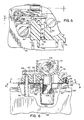
- Fig. 3 is a view, partially in section, taken generally along the line 3-3 of Fig. 2.
- Fig. 4 is a view of the primer chamber taken generally along the line 4-4 of Fig. 3, with the primer bulb removed.
- Fig. 5 shows the fuel passageways from the fuel tank to the primer chamber and is taken generally along the line 5-5 of Fig. 4.
- Fig. 6 is a section view taken generally along line 6-6 of Figs. 5 and 7.
- Fig. 7 is a section view looking downward toward the fuel tank of the assembly and is taken generally along the line 7-7 of Fig. 6.
- Fig. 8 is a section view looking upward toward the carburetor and is taken generally along line 8-8 of Fig. 6.
- Fig. 9 is a section view taken generally along line 9-9 of Fig. 7.
- Fig. 10 is a partial section view taken generally along line 10-10 of Fig. 7.
- Fig. 11 is a section view taken generally along line 11-11 of Fig. 7.
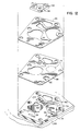
- Fig. 12 is an exploded view showing the fuel tank, fuel tank top, pump diaphragm, gasket and carburetor of the assembly of Fig. 2.
- FIG. 1 A diagramatic illustration of the flow circuitry of the preferred embodiment is shown in Fig. 1.
- the priming circuit is specifically suited for use with a floatless carburetor of the type having an impulse fuel pump 10 which is in direct communication with the throttle bore 12 of the carburetor.
- a biasing element such as compression spring 14 holds the pump diaphragm 16 in the fixed position.
- the resulting negative pressure in the throttle bore 12 acts against the force of the compression spring 14 to pull the diagraphm 16 up as shown, to expand the pump chamber 18.
- the primer system 36 of the subject invention is a wet primer and is in direct communication with the fuel supply via the fuel line 22 and the pickup tube 26.
- the primer system includes a primer bulb 38, an orifice 40 and a fuel orifice 42. Initially when the primer bulb is closed to contract the primer chamber 44, the increase in pressure opens the check valve 46 and the pump check valve 20, while closing the pickup tube check valve 24. When the primer bulb 38 is released to expand the chamber 44, check valves 20 and 46 are closed and check valve 24 is opened, drawing fuel into the pickup tube 26, into the fuel line 22 and into the primer chamber 44.
- valve 24 closes, and valves 20 and 46 open, releasing the fuel from the primer chamber into the throttle bore 12 via the orifice 40 and check valve 46.
- the fuel in the primer chamber is also forced back through the fuel port 42 and into fuel line 22, to open the check valve 20 and introduce fuel from the primer chamber into the pump chamber 18, and from the pump chamber 18 through the reservoir line 30 and check valve 32 into the reservoir 34.
- the back pressure on the pickup tube in this phase closes the pickup tube check valve 24.
- the primer system can be used to both directly enrich the air fuel mixture in the carburetor throttle bore 12 and also to fill the reservoir 34 to enhance cold starting.
- the invention as depicted in the preferred embodiment of Figs. 2-12 is best understood if the various circuit components in Fig. 1 are correlated to the remaining drawing figures.
- the primer assembly 36 and primer bulb 38 are shown in Figs. 2 and 3.
- the primer chamber 44 is shown in Fig. 4 with the orifice 40 and the fuel orifice 42 clearly in view.
- the fuel line 22 connecting the primer chamber 44 with the pickup tube 26 is best shown in Figs. 5 and 6 and includes additional core passageways 25 and 27, as clearly shown in Fig. 5.
- the check valve 20 comprises the reed valve portion of the diaphragm 68, shown in Fig. 12.
- the check valve 20 is shown in assembled relationship with the carburetor and fuel tank in Figs.
- the impulse pump 10 is best shown in Fig. 9 and includes the spring 14 mounted in the carburetor spring chamber 200.
- the pump chamber 18 is included in the fuel tank top 50.
- the pump diaphragm 16 is a portion of the diaphragm assembly 68 shown in Fig. 12.
- the pump exit passage 30 is best shown in Fig. 7 and is in communication with the check valve 32 which defined by the reed valve 32 portion of the diaphragm 68 shown in Fig. 12.
- the passage 33 for communicating the check valve 32 with the reservoir 34 is best shown in Figs. 10 and 11.
- the floatless carburetor 50 of the preferred embodiment is of an integral unitary design including a base 52 for the primer assembly 36, an air intake tube 54, and an induction or outlet tube 56 all mounted on a carburetor base 58 which is secured to the tank top 60 via a plurality of mounting screws 64 or the like.
- the tank top 60 is also of a molded, integral design and includes an integral fill tube 62.
- the entire fuel delivery system of the preferred embodiment is self contained in the carburetor 50 and the fuel tank top 60, with gasket 66 and diaphragm 68.
- the carburetor 50 is mounted on the tank top 60 with the gasket 66 and diaphragm 68 (Figs. 3 and 12) placed between the carburetor base 58 and the mounting boss 70 provided on the tank top 60 (Figs. 3, 6, and 12).
- the gasket and diaphragm form a tight seal between the carburetor and fuel tank to eliminate any leakage.
- the primer assembly 36 includes the domed, resilient primer bulb 38 which is mounted on a sealing wall 72 (Figs. 3 and 4) provided on the carburetor primer base 52.
- the outer wall 74 defines a shroud for protecting the bulb against damage, exposing only the domed end thereof.
- a retainer ring 76 (Fig. 3) is inserted in the channel between the inner wall 72 and the outer wall 74 to securely retain the primer bulb in place and to provide a circumferential seal against the enlarged lip or integral o-ring 78 of the bulb, providing an annular seal between the bulb and the carburetor for defining the primer chamber 44.
- the primer chamber 44 is in communication with the carburetor throat at orifice 40 and is in communication with the fuel tank through fuel orifice 42.
- An air bleed passage 80 is provided in the channel between the inner wall 72 and the outer wall 74 of the primer base 52.
- a fuel pickup tube 26 is press fit into the carburetor base 58 and extends through the tank top 60 to the bottom of the fuel tank 28 (Fig. 3).
- the hollow interior of the tube 26 is in communication with the fuel line 22 via an intersecting core passage 126 (Fig. 6) provided in the carburetor.
- the open lower end 86 (Fig. 3) of the tube 26 includes the ball check valve 24 to maintain one way flow in the tube.
- the core passageway which defines the fuel line 22 is in direct communication with the intersecting core passageway 27 which leads directly to the fuel orifice 42 of the primer base (Fig. 5).
- a restrictor 92 is secured in the core passage 27 to restrict the flow through the primer orifice 42, providing a balanced flow between the choke orifice 40 and the fuel orifice 42 when the primer bulb is depressed to release fuel from the primer chamber.
- the gasket 66 and diaphragm 68 are designed to provide not only the seal between the carburetor 50 and the fuel tank top 60, but also to provide a membrane area defining the pump diaphragm 16 and a pair of reed flaps defining the check valves 20 and 32.
- the gasket 66 is made of non-asbestos material or the like and the diaphragm 68 is a rubber coated fabric or the like. The gasket and diaphragm are secured in contact with one another on all mated surface areas to define a tight, leak-proof seal between the carburetor 50 and fuel tank top 60.
- the reed valve 20 When assembled as shown in Figs. 9, 10 and 11, the reed valve 20 is in communication with the carburetor core passage 25 and the chamber 23 and core passage 123 of the fuel tank top, defining the fuel pathway between the reed valve 20 and the pump chamber 18.
- the reed valve 20 is normally in a flat, generally closed position.
- the chamber 23 is in communication with a core passageway 123 in the fuel tank top, whereby the fuel is introduced into the pump chamber 18.
- the fuel is exited through core passage 30 in the fuel tank top 60 to force open the reed check valve 32.
- the reed valve 32 As best shown in Figs. 10 and 11, as the fuel flows from passageway 123 into chamber 18 and is exited through core passage 30 into an intersecting core passageway 130, it forces the reed valve 32 upward and open into the chamber 33 provided in the carburetor 50.
- Chamber 33 is open to reservoir 34, whereby the fuel in chamber 33 is exited into the reservoir.
- the primer assembly is used not only to provide a direct priming charge through the orifice 40 into the barrel of the carburetor, but also to fill the reservoir 34 to assure starting.
- the diaphragm 16 of the impulse pump 10 is normally biased in the extended position by means such as the compression spring 14 which is mounted on an integral post 112 provided in the body of the carburetor. When so biased, the diaphragm contracts the size of the pump cavity 18 which is provided as an integral chamber in the tank top 60.
- the reed check valves 20 and 32 are in communication with the pump chamber 18, as previously described.
- the negative pressure overcomes the compression force of spring 112 and draws the diaphragm up toward the carburetor to expand pump chamber 18 and draw fuel from the fuel tank into the pump chamber.
- spring 112 When the engine is in its compression stroke, a near atmospheric to slightly positive pressure is created in the throttle bore 12 and this is translated into the spring chamber 200 via the orifice 202 to push, in combination with spring 112, the diaphragm 16 to its fully extended position to contract chamber 18 and force fuel through check valve 32 and chamber 33 into the reservoir 34.
- the impulse pump 10 is operative to pump fuel from the fuel tank 28 into the reservoir 34.
- a stem assembly 204 is mounted in an integral sleeve 206 provided in the carburetor. When assembled, the sleeve and stem extend down into the reservoir 34.
- a fine mesh screen 208 is provided over the open lower end of the sleeve 206 and serves as a fuel filter.
- the nozzle 204 is a standard fuel jet such as those commonly used in float feed carburetors and known in the art. The nozzle is sealed in the sleeve by a typical o-ring seal 210. The jet is of a smaller diameter than the inside diameter of the stem sleeve with the space between the sleeve and the outer surface of the jet being open to air.
- a plurality of air orifices 212 communicate the jet passage 214 with the air in the space between the sleeve and the jet to provide a balanced, pre-selected atomized air fuel mixture when the fuel in the jet is drawn into the carburetor venturi by a negative pressure during an engine intake stroke.
- a venturi tube 216 is placed between the air intake tube 54 and the induction tube 56 of the carburetor 50.
- the jet opening 214 is disposed outboard of the narrowest restriction of the venturi, whereby the fuel released from the jet and the air being introduced via the air intake tube 54 are accelerated and atomized prior to being introduced into the throttle chamber 12.
- the outlet or induction tube 56 of the carburetor includes a pair of axially aligned mounting bosses 215 with apertures therethrough for receiving a throttle shaft 220.
- a standard throttle plate 218 is mounted on the shaft 220 to selectively control the size of the opening in the throttle bore 12 in advance of the induction tube 56.
- an integral stop 224 is provided on the outer end of the induction tube 56 to restrict the rotational movement of the throttle shaft 220 by providing a positive stop for the shaft radial extension 222.
Landscapes
- Engineering & Computer Science (AREA)
- Chemical & Material Sciences (AREA)
- Combustion & Propulsion (AREA)
- Mechanical Engineering (AREA)
- General Engineering & Computer Science (AREA)
- Means For Warming Up And Starting Carburetors (AREA)
- Control Of The Air-Fuel Ratio Of Carburetors (AREA)
Claims (4)
- Startkreis für einen Vergaser (50) für eine Brennkraftmaschine, welcher Vergaser von der Art mit einem Lufteinlaß (54), einer Drosselkammer (12), einer Ansaugkammer (56) und einem Brennstoffreservoir (34) ist, aus dem Brennstoff in die Drosselkammer (12) gesaugt wird, wo er mit durch den Lufteinlaß (54) eintretender Luft gemischt und in die Ansaugkammer (56) abgegeben wird, um die Verbrennung im Motor aufrechtzuerhalten, wobei ein Brennstoffzufuhrsystem (26, 23, 18, 30, 33) aus dem Brennstofftank (28) zu dem Brennstoffreservoir (34) des Vergasers (50) vorhanden ist, wobei der Startkreis aufweist:a) eine expandierbare/kontrahierbare Startkammer (44),b) ein erstes Brennstoffleitungsmittel (22), das die Startkammer (44) mit dem Brennstoffzufuhrsystem (26, 23, 18, 30, 33) verbindet,c) ein zweites Brennstoffleitungsmittel (40, 106), das die Startkammer (44) mit der Drosselkammer (12) verbindet,d) ein erstes Ventilmittel (24), das sich zwischen dem Brennstofftank (28) und der Startkammer (44) befindet und auswählbar zwischen einer offenen Stellung, wenn die Startkammer (44) expandiert ist, und einer geschlossenen Stellung, wenn die Startkammer (44) kontrahiert ist, beweglich ist,e) ein zweites Ventilmittel (46), das sich zwischen der Drosselkammer (12) und der Startkammer (44) befindet und auswählbar zwischen einer offenen Stellung, wenn die Startkammer (44) kontrahiert ist, und einer geschlossenen Stellung, wenn die Startkammer (44) expandiert ist, beweglich ist,f) ein drittes Ventilmittel (20), das sich zwischen dem Brennstoffreservoir (34) und der Startkammer (44) befindet und auswählbar zwischen einer offenen Stellung, wenn die Startkammer (44) kontrahiert ist, und einer geschlossenen Stellung, wenn die Startkammer (44) expandiert ist, beweglich ist, undg) einer Brennstoffpumpe (10), die in dem Brennstoffzufuhrsystem angeordnet ist und eine Pumpenkammer (18) in Verbindung mit dem Brennstofftank (28) und dem Reservoir (34) aufweist, und so anspricht, abwechselnd Brennstoff aus dem Brennstofftank (28) anzusaugen und ihn in das Reservoir (34) einzuführen,dadurch gekennzeichnet, daß das erste Brennstoffleitungsmittel (22) mit dem Brennstoffzufuhrsystem zwischen dem ersten Ventilmittel (24) und dem dritten Ventilmittel (20) verbunden ist, wobei das dritte Ventilmittel (20) zwischen der Verbindung des ersten Brennstoffleitungsmittels (22) und der Pumpe (10) angeordnet und beweglich ist zwischen der geöffneten Stellung, wenn die Pumpe (10) Brennstoff auf dem Brennstofftank (28) ansaugt, und der geschlossenen Stellung, wenn die Pumpe (10) Brennstoff in das Reservoir (34) einführt.
- Startkreis nach Anspruch 1, welche ferner vierte Ventilmittel (32) zwischen der Brennstoffpumpe (10) und dem Reservoir (34) aufweist und auswählbar zwischen einer geschlossenen Stellung, wenn die Pumpe (10) Brennstoff aus dem Brennstofftank (28) ansaugt, und einer geöffneten Stellung, wenn die Pumpe (10) keinen Brennstoff aus dem Brennstofftank (28) ansaugt, beweglich ist.
- Startkreis nach Anspruch 2, wobei das vierte Ventilmittel (32) auch in die offene Stellung beweglich ist, wenn die Startkammer (44) kontrahiert ist.
- Startkreis nach einem der Ansprüche 1 bis 3, wobei die Brennstoffpumpe (10) eine Pumpe vom Impulstyp aufweist, die auf den Motorzyklus zwischen negativen und positiven Druckhüben anspricht, um unter negativem Druck Brennstoff aus dem Brennstofftank (28) anzusaugen und unter positivem Druck Brennstoff in das Reservoir (34) einzuführen.
Applications Claiming Priority (2)
| Application Number | Priority Date | Filing Date | Title |
|---|---|---|---|
| US07/590,014 US5058544A (en) | 1990-09-28 | 1990-09-28 | Floatless carburetor with integral primer system |
| US590014 | 1990-09-28 |
Publications (2)
| Publication Number | Publication Date |
|---|---|
| EP0478330A1 EP0478330A1 (de) | 1992-04-01 |
| EP0478330B1 true EP0478330B1 (de) | 1995-07-12 |
Family
ID=24360531
Family Applications (1)
| Application Number | Title | Priority Date | Filing Date |
|---|---|---|---|
| EP91308800A Expired - Lifetime EP0478330B1 (de) | 1990-09-28 | 1991-09-26 | Schwimmerloser Vergaser mit integrierter Startvorrichtung |
Country Status (5)
| Country | Link |
|---|---|
| US (1) | US5058544A (de) |
| EP (1) | EP0478330B1 (de) |
| JP (2) | JPH05149201A (de) |
| CA (1) | CA2052332C (de) |
| DE (1) | DE69111170T2 (de) |
Families Citing this family (13)
| Publication number | Priority date | Publication date | Assignee | Title |
|---|---|---|---|---|
| FR2715193B1 (fr) * | 1994-01-19 | 1996-03-08 | Lucas France | Ensemble filtre à pompe d'amorçage. |
| US5750056A (en) * | 1996-09-18 | 1998-05-12 | Murray, Inc. | Remotely controlled primer actuator for power equipment engines |
| US6152431A (en) | 1998-05-06 | 2000-11-28 | Tecumseh Products Company | Carburetor having extended prime |
| US6741899B1 (en) * | 2000-02-07 | 2004-05-25 | Visteon Global Tech., Inc. | System and method for designing a component |
| US20050045197A1 (en) * | 2003-08-28 | 2005-03-03 | Gelder Steven K. | Multiple drug delivery system & method |
| US7165536B2 (en) * | 2004-06-14 | 2007-01-23 | Tecumseh Products Company | Evaporative emissions control system for small internal combustion engines |
| WO2008016916A2 (en) * | 2006-08-01 | 2008-02-07 | Pcrc Products | Small engine operation components |
| US20080251053A1 (en) * | 2007-04-16 | 2008-10-16 | Shears Peter D | Evaporative emissions control system |
| US20080251055A1 (en) * | 2007-04-16 | 2008-10-16 | Briggs & Stratton Corporation | Evaporative emissions control system |
| JP5666855B2 (ja) | 2010-09-03 | 2015-02-12 | ザマ・ジャパン株式会社 | 始動装置及びそれを用いた気化器 |
| CN104481736B (zh) * | 2014-11-05 | 2017-01-25 | 成都恒高机械电子有限公司 | 一种大排量竞技越野摩托车用平吸柱塞式化油器 |
| US10465642B2 (en) | 2017-03-27 | 2019-11-05 | Kohler Co. | Carburetor drain |
| US11008978B2 (en) | 2019-03-05 | 2021-05-18 | Kohler Co. | Bail driven stale fuel evacuation |
Family Cites Families (9)
| Publication number | Priority date | Publication date | Assignee | Title |
|---|---|---|---|---|
| US1345516A (en) * | 1918-04-15 | 1920-07-06 | Elgin Gas Motor Company | Carbureter |
| US3323293A (en) * | 1965-02-23 | 1967-06-06 | Briggs & Stratton Corp | Primer for internal combustion engines |
| US3415236A (en) * | 1966-12-16 | 1968-12-10 | Briggs & Stratton Corp | Primer for small internal combustion engines |
| US3494343A (en) * | 1968-03-15 | 1970-02-10 | Tillotson Mfg Co | Priming device for internal combustion engines |
| DE2054525A1 (de) * | 1970-11-05 | 1972-05-10 | Mikuni Kogyo Co., Ltd., Tokio | Membranvergaser mit Starteinrichtung |
| US4228110A (en) * | 1979-06-04 | 1980-10-14 | Melvin Magnet | Gasoline priming pump for carburetors |
| JPS61255256A (ja) * | 1985-05-08 | 1986-11-12 | Nippon Carbureter Co Ltd | 膜式気化器 |
| US4684484A (en) * | 1986-05-27 | 1987-08-04 | Tecumseh Products Company | Primer system and method for priming an internal combustion engine |
| US4699739A (en) * | 1986-10-17 | 1987-10-13 | Armes Paul W | Gasoline engine choking arrangement |
-
1990
- 1990-09-28 US US07/590,014 patent/US5058544A/en not_active Expired - Lifetime
-
1991
- 1991-09-26 CA CA002052332A patent/CA2052332C/en not_active Expired - Fee Related
- 1991-09-26 EP EP91308800A patent/EP0478330B1/de not_active Expired - Lifetime
- 1991-09-26 DE DE69111170T patent/DE69111170T2/de not_active Expired - Fee Related
- 1991-09-27 JP JP3249854A patent/JPH05149201A/ja active Pending
-
1995
- 1995-11-27 JP JP1995012489U patent/JP2546445Y2/ja not_active Expired - Fee Related
Also Published As
| Publication number | Publication date |
|---|---|
| EP0478330A1 (de) | 1992-04-01 |
| JPH08833U (ja) | 1996-05-21 |
| US5058544A (en) | 1991-10-22 |
| DE69111170T2 (de) | 1996-01-25 |
| JP2546445Y2 (ja) | 1997-09-03 |
| CA2052332C (en) | 1997-12-30 |
| CA2052332A1 (en) | 1992-03-29 |
| DE69111170D1 (de) | 1995-08-17 |
| JPH05149201A (ja) | 1993-06-15 |
Similar Documents
| Publication | Publication Date | Title |
|---|---|---|
| EP0478330B1 (de) | Schwimmerloser Vergaser mit integrierter Startvorrichtung | |
| US4375206A (en) | Fuel primer and enrichment system for an internal combustion engine | |
| JP2008169831A (ja) | 燃料システムのための始動回路 | |
| US4447370A (en) | Supplementary fuel supply mechanism for internal combustion engines | |
| US4735751A (en) | Primer system and method for priming an internal combustion engine | |
| CN101139957A (zh) | 在化油器中供给辅助燃料和空气 | |
| US6533254B1 (en) | Carburetor fuel pump | |
| US4684484A (en) | Primer system and method for priming an internal combustion engine | |
| EP1207294A2 (de) | Vergaser mit Entlüftungssystem | |
| US6913250B2 (en) | Carburetor arrangement | |
| JPH0147623B2 (de) | ||
| JP2003097353A (ja) | 気化器 | |
| US4926808A (en) | Primer bulb check valve system for an internally vented bowl primer carburetor | |
| US4197825A (en) | Primer bulb retainer | |
| US3323293A (en) | Primer for internal combustion engines | |
| US4660516A (en) | Fuel primer and enrichment system for an internal combustion engine | |
| CA2270786C (en) | Carburetor having extended prime | |
| US7210441B1 (en) | Priming and purging system and method for an internal combustion engine | |
| US4509471A (en) | Start system for internal combustion engines | |
| US6644631B2 (en) | Diaphragm-type carburetor | |
| US6840508B2 (en) | Push button air primer for carburetor | |
| CA1279537C (en) | Primer system and method for priming an internal combustion engine | |
| JPH0341082Y2 (de) | ||
| JPH0341083Y2 (de) | ||
| JP2997896B2 (ja) | ダイヤフラム式気化器を備えたエンジンの始動装置 |
Legal Events
| Date | Code | Title | Description |
|---|---|---|---|
| PUAI | Public reference made under article 153(3) epc to a published international application that has entered the european phase |
Free format text: ORIGINAL CODE: 0009012 |
|
| AK | Designated contracting states |
Kind code of ref document: A1 Designated state(s): DE FR GB IT SE |
|
| 17P | Request for examination filed |
Effective date: 19920909 |
|
| 17Q | First examination report despatched |
Effective date: 19930405 |
|
| GRAA | (expected) grant |
Free format text: ORIGINAL CODE: 0009210 |
|
| AK | Designated contracting states |
Kind code of ref document: B1 Designated state(s): DE FR GB IT SE |
|
| REF | Corresponds to: |
Ref document number: 69111170 Country of ref document: DE Date of ref document: 19950817 |
|
| ITF | It: translation for a ep patent filed | ||
| ET | Fr: translation filed | ||
| PLBE | No opposition filed within time limit |
Free format text: ORIGINAL CODE: 0009261 |
|
| STAA | Information on the status of an ep patent application or granted ep patent |
Free format text: STATUS: NO OPPOSITION FILED WITHIN TIME LIMIT |
|
| 26N | No opposition filed | ||
| REG | Reference to a national code |
Ref country code: GB Ref legal event code: IF02 |
|
| PGFP | Annual fee paid to national office [announced via postgrant information from national office to epo] |
Ref country code: FR Payment date: 20080915 Year of fee payment: 18 Ref country code: IT Payment date: 20080926 Year of fee payment: 18 |
|
| PGFP | Annual fee paid to national office [announced via postgrant information from national office to epo] |
Ref country code: DE Payment date: 20081002 Year of fee payment: 18 |
|
| PGFP | Annual fee paid to national office [announced via postgrant information from national office to epo] |
Ref country code: SE Payment date: 20080908 Year of fee payment: 18 |
|
| PGFP | Annual fee paid to national office [announced via postgrant information from national office to epo] |
Ref country code: GB Payment date: 20081001 Year of fee payment: 18 |
|
| EUG | Se: european patent has lapsed | ||
| GBPC | Gb: european patent ceased through non-payment of renewal fee |
Effective date: 20090926 |
|
| REG | Reference to a national code |
Ref country code: FR Ref legal event code: ST Effective date: 20100531 |
|
| PG25 | Lapsed in a contracting state [announced via postgrant information from national office to epo] |
Ref country code: DE Free format text: LAPSE BECAUSE OF NON-PAYMENT OF DUE FEES Effective date: 20100401 Ref country code: FR Free format text: LAPSE BECAUSE OF NON-PAYMENT OF DUE FEES Effective date: 20090930 |
|
| PG25 | Lapsed in a contracting state [announced via postgrant information from national office to epo] |
Ref country code: GB Free format text: LAPSE BECAUSE OF NON-PAYMENT OF DUE FEES Effective date: 20090926 |
|
| PG25 | Lapsed in a contracting state [announced via postgrant information from national office to epo] |
Ref country code: IT Free format text: LAPSE BECAUSE OF NON-PAYMENT OF DUE FEES Effective date: 20090926 |
|
| PG25 | Lapsed in a contracting state [announced via postgrant information from national office to epo] |
Ref country code: SE Free format text: LAPSE BECAUSE OF NON-PAYMENT OF DUE FEES Effective date: 20090927 |