EP0478209B1 - Procédé et dispositif de transmission de données - Google Patents
Procédé et dispositif de transmission de données Download PDFInfo
- Publication number
- EP0478209B1 EP0478209B1 EP91308490A EP91308490A EP0478209B1 EP 0478209 B1 EP0478209 B1 EP 0478209B1 EP 91308490 A EP91308490 A EP 91308490A EP 91308490 A EP91308490 A EP 91308490A EP 0478209 B1 EP0478209 B1 EP 0478209B1
- Authority
- EP
- European Patent Office
- Prior art keywords
- data
- clock signals
- binary
- byte
- Prior art date
- Legal status (The legal status is an assumption and is not a legal conclusion. Google has not performed a legal analysis and makes no representation as to the accuracy of the status listed.)
- Expired - Lifetime
Links
Images


Classifications
-
- H—ELECTRICITY
- H04—ELECTRIC COMMUNICATION TECHNIQUE
- H04N—PICTORIAL COMMUNICATION, e.g. TELEVISION
- H04N1/00—Scanning, transmission or reproduction of documents or the like, e.g. facsimile transmission; Details thereof
- H04N1/41—Bandwidth or redundancy reduction
- H04N1/411—Bandwidth or redundancy reduction for the transmission or storage or reproduction of two-tone pictures, e.g. black and white pictures
- H04N1/413—Systems or arrangements allowing the picture to be reproduced without loss or modification of picture-information
- H04N1/419—Systems or arrangements allowing the picture to be reproduced without loss or modification of picture-information in which encoding of the length of a succession of picture-elements of the same value along a scanning line is the only encoding step
-
- G—PHYSICS
- G06—COMPUTING; CALCULATING OR COUNTING
- G06K—GRAPHICAL DATA READING; PRESENTATION OF DATA; RECORD CARRIERS; HANDLING RECORD CARRIERS
- G06K15/00—Arrangements for producing a permanent visual presentation of the output data, e.g. computer output printers
-
- G—PHYSICS
- G06—COMPUTING; CALCULATING OR COUNTING
- G06K—GRAPHICAL DATA READING; PRESENTATION OF DATA; RECORD CARRIERS; HANDLING RECORD CARRIERS
- G06K2215/00—Arrangements for producing a permanent visual presentation of the output data
- G06K2215/0002—Handling the output data
- G06K2215/0062—Handling the output data combining generic and host data, e.g. filling a raster
- G06K2215/0071—Post-treatment of the composed image, e.g. compression, rotation
-
- G—PHYSICS
- G06—COMPUTING; CALCULATING OR COUNTING
- G06K—GRAPHICAL DATA READING; PRESENTATION OF DATA; RECORD CARRIERS; HANDLING RECORD CARRIERS
- G06K2215/00—Arrangements for producing a permanent visual presentation of the output data
- G06K2215/0082—Architecture adapted for a particular function
- G06K2215/0097—Printing on special media, e.g. labels, envelopes
Definitions
- This invention relates to a method of data transmission and in particular to a method of outputting data signals to a printing device.
- US 4,228,467 discloses a facsimile transmission system in which a sequence of binary signals is run-length encoded into words representing strings of contiguous binary bits having the same value.
- the words are entered one at a time into a register and the word is read out to set a counter to a value corresponding to the word.
- Clock signals are output to a printer and to the counter to decrement the counter. When the counter reaches zero count, the supply of clock signals is terminated.
- EP A-0 050 338 discloses a picture information processing and storage device. Scanning information is converted to run-length codes. Decoding is effected by setting a counter to the value of the run-length code and decrementing the counter to zero. A further disclosure of run-length encoded data is provided by WO-A-8 501 174.
- Printing devices capable of selectively printing dots in a row are used to print characters or a graphic pattern by repeatedly operating the printhead in a succession of print cycles to print selected dots in a succession of rows on a print receiving medium.
- An example of such a printing device is a thermal dot printhead.
- Thermal dot printheads comprise a row of resistive print elements through which electric current is passed selectively to heat selected elements. The heated elements of the printhead cause an impression to be printed on a medium either by an ink transfer process in which ink carried by a backing layer is caused to be removed from the backing layer and deposited on the print receiving medium or by direct thermal activation of a heat sensitised medium.
- Each print element is capable of printing a dot on the medium in a line aligned with the row of print elements.
- Printing of characters or graphic patterns is effected by relative movement between the printhead and the medium in a direction transverse to the row of print elements during which the print elements are selectively heated to build up the required impression line by line.
- Energisation of the print elements is controlled by means of a register having a plurality of stages corresponding in number to the number of print elements. Each stage of the register is associated with a different one of the print elements respectively. For each line of printing, the stages of the register are loaded with a binary digit representing energisation or non-energisation of the corresponding print element. For example print elements associated with stages loaded with binary one will be energised while print elements associated with stages loaded with binary zero will not be energised.
- thermal printheads in postage franking machines to effect printing of a franking impression on items of mail.
- a printhead for such use is proposed to provide a resolution of 8 dots/mm and to have a printing width of 30mm. Consequently such a head is provided with 240 energisable print elements and requires a register having 240 stages into which a corresponding number of print data bits must be loaded for each line of dots to be printed. For any given print speed, i.e. rate of printing line by line, there is a maximum time interval for the loading of the print data. While parallel loading of the register enables the print data to be loaded in the duration of this time interval even for relatively high speeds of printing, generally, commercially available thermal print heads are designed for serial loading of the print data.
- Usually electronic circuits of a franking machine include a micro-processor which carries out accounting and control functions of the machine and the operation of the microprocessor imposes limitations on the rate at which print data for controlling energisation of the print elements of the printhead can be output.
- Print data is usually stored as a bit map in which each possible dot position of an impression to be printed is represented by a binary data bit in a bit map. This requires the provision of a substantial number of storage locations in memory.
- the microprocessor is required to output information for each bit of print data sent to the printhead. Typically six instructions are required to be executed by the microprocessor for the output of each bit of print data. Thus for a printhead with 240 print elements, output of print data defining a line of print the microprocessor is required to execute 1440 instructions.
- a method of storing a data message and outputting signals corresponding to said stored data message including the steps of storing said data message as a data byte having a value representing the number of bits in a string of contiguous bits having the same one binary value; setting a data line to a first state representing the binary value of the string of bits represented by said data byte; outputting a series of clock signals from a source of clock signals and utilising a counter to control the output of clock signals so that the number of clock signals is equal to the number of bits in the string of bits represented by said data byte is characterised by the steps of storing a plurality of bytes representing a multi-bit data message, incrementing the counter with said clock signals; terminating output of said clock signals in response to the counter reaching a state corresponding to the value of a first one of said data bytes; and switching the data line to a second state representing the other binary value; and repeating the sequence of aforesaid steps of incrementing the counter with said clock signals; terminating output
- apparatus for storing a data message and outputting binary signals corresponding to said data message
- a microprocessor 10 is connected to a bus 11 to which a number of peripheral and memory devices are connected.
- the microprocessor is operable under program sequences stored in a read only memory (ROM) 12 to carry out accounting and control functions of the franking machine.
- a random access memory 13 is connected to the bus and is utilised by the microprocessor as a working store.
- Postage accounting data relating to usage of the franking machine in franking postal items is stored in non-volatile memories 14, 15 also connected to the bus 11. For purposes of security and maintenance of integrity of the accounting data in the event of a mal-function, the accounting data is stored in duplicate in each of the memories 14, 15.
- the accounting data comprises a value of credit available for use in franking, a tote value which is the accumulated value of postage used in franking items, a count of the number of items franked and a count of the number of items franked with a postage charge in excess of a predetermined value.
- Input of values of postage charge required to be franked, other data and commands to control operation of the machine is effected by means of a keyboard 16 connected to the bus 11.
- a display device 17 connected to the bus is operated by the microprocessor to echo keyboard entries of postage values and to display information to assist users in uses of the machine.
- An input/output port 18 connected to the bus handles transmission of signals output from the microprocessor to other devices and of signals input to the microprocessor from those devices.
- a motor control circuit 19 is controlled by signals output via the input/output port 18 to control energisation of a main drive motor 20 of means for feeding mail items past a printhead 21.
- the control circuit also controls operation of an impression control motor 31 which effects application of pressure to urge mail items toward the printhead so that a thermal transfer ribbon interposed between the printhead and the mail item is pressed into ink transfer engagement with the mail item.
- the thermal transfer ribbon is drawn by its engagement with the mail item past the printhead and the used ribbon is wound onto a take up spool or reel driven by a take up motor 32 controlled by control circuit 19.
- Feeding of the mail items is sensed by means of a tachometer 22 which inputs signals to the microprocessor via the input/output port 18 to synchronise the line by line printing of the franking impression with the feeding of the mail items.
- the thermal printhead 21 is connected to the input/output port 18 so as to receive multi-bit data messages comprising print data signals and strobe signals from the microprocessor 10.
- the microprocessor loads print data defining a plurality of lines of print to form a franking impression to be printed in memory, which may be RAM 13, and outputs successive lines of this print data in a succession of print cycles, one line of data being output in each cycle.
- a strobe signal from the microprocessor causes the print data in the printhead register to energise the printhead elements in dependence upon the print data.
- the print data for a line of print is stored in memory 13 as a number of bytes each corresponding respectively to a group of contiguous binary ones and zeros in the print data.
- the bytes are each of eight bits and the magnitude of each byte represents the number of print data bits in a string for the group of bits corresponding to the byte.
- the width of any franking impression to be printed is less than the overall width of the printhead and hence, with binary one representing a dot to be printed, the ends of a line of print data are always binary zeros. Accordingly the initial string of bits for a line of print data always consists of zeros and hence the first byte always represents a number of zeros.
- the second byte represent a number of ones, the third byte a number of zeros and so on alternately. It will be appreciated that lines of print data will be represented by different numbers of bytes in dependence upon the number of groups of contiguous zeros and ones in the data.
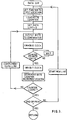
- the print data for a line of print also includes a number having a value equal to the number of bytes representing the print data for a line of print. As illustrated by the block diagram of Figure 2 and the flow chart of Figure 3, during a printing cycle the printing data for a line of print is output one byte at a time via the input/output port 18 and lines 23 to one side of an eight bit magnitude comparator 24. An input to the other side of the comparator 24 is from a counter 25.
- the counter is driven by clock signals from a clock generator 26 enabled by an enable signal on line 27. Clock signals from generator 26 are output on line 28 to clock data signals into the register of the printhead in dependence upon the state of a data line 29. Thus the count from counter 25 is equal to the number of data bits clocked to the printhead register.
- the comparator When the count from the counter is equal to the value of the byte loaded into the comparator 24, the comparator generates a count equal signal on line 30 which is sent via the input/output port 18 to the microprocessor to indicate that the required number of bits of one value have been sent to the printhead and that the next byte of print data requires loading into the comparator.
- the clock generator 26 is inhibited while loading is effected and the state of data line 29 is complimented so that it is toggled from its previous state while the previous byte was in the comparator to an opposite state.
- the data line is toggled so that the next byte controls loading of a number of data bits of the other binary value.
- the microprocessor Upon completion of loading the data bits for a line of print, and at a time determined inter alia by output from the tachometer, the microprocessor outputs a strobe signal on line 33 to the printhead to effect energisation of print elements in dependence upon the loaded print data to effect printing of a line of the required impression.
- the microprocessor sets a counter equal to the value of the number which is equal to the number of bytes representing print data for a line. This counter is decremented by unity for each loading of a byte into the comparator. Inspection of the counter by the microprocessor provides an indication of when loading of a complete line of print data has been accomplished.
- the speed of data handling is enhanced because the microprocessor is required to generate an output only when the state of the data line is required to be toggled. For a typical franking impression this may occur approximately thirteen times for each line of print whereas for previous proposed methods of print data output the microprocessor has been required to generate an output for each bit of print data sent to the printhead. If the microprocessor is required to execute six instructions for each output generated, with the data transmission system described hereinbefore the microprocessor is required to execute only 78 instructions for a typical line of print forming a franking impression as compared with 1440 instructions when output is generated for each print data bit thereby providing a decrease in speed of data handling of approximately 20 times. An additional benefit is provided in that less memory space is required to store the bytes representing print data than would be required to store the print data in bit map form.
- the method of data transmission in accordance with the invention may be used for transmission of print data to printing devices other than thermal print heads, for example print heads using other printing technologies to selectively print a plurality of dots in rows. Furthermore the method of data transmission may be utilised for transmission of data serially to devices other than print heads.
Landscapes
- Engineering & Computer Science (AREA)
- General Engineering & Computer Science (AREA)
- Physics & Mathematics (AREA)
- General Physics & Mathematics (AREA)
- Theoretical Computer Science (AREA)
- Multimedia (AREA)
- Signal Processing (AREA)
- Record Information Processing For Printing (AREA)
- Accessory Devices And Overall Control Thereof (AREA)
Claims (5)
- Procédé de stockage d'un message de données, et de fourniture en sortie de signaux correspondant au message de données stocké, comprenant les étapes consistant à stocker le message de données dans une mémoire (13) sous la forme d'un octet de données ayant une valeur qui représente le nombre de bits dans une suite de bits contigus présentant une même valeur binaire ; régler une ligne de données (29) dans un premier état représentant la valeur binaire de la suite de bits représentée par l'octet de données ; fournir en sortie une série de signaux d'horloge provenant d'une source de signaux d'horloge (26), et utiliser un compteur (25) pour commander la sortie des signaux d'horloge de façon que le nombre de signaux d'horloge soit égal au nombre de bits dans la suite de bits représentée par l'octet de données,
caractérisé par
les étapes consistant à :stocker dans la mémoire (13) un certain nombre d'octets représentant un message de données multibit, en incrémentant le compteur (25) par les signaux d'horloge ;couper la sortie des signaux d'horloge lorsque le compteur (25) atteint un état qui correspond à la valeur d'un premier des octets de données ;commuter la ligne de données (29) dans un second état représentant l'autre valeur binaire ;répéter la séquence des étapes ci-dessus d'incrémentation du compteur (25) par les signaux d'horloge ;couper la sortie des signaux d'horloge lorsque le compteur (25) atteint un état qui correspond à un octet de données suivant, et commuter la ligne de données (29), le premier octet de données et le second octet de données se trouvant dans une séquence qui correspond à la séquences des suites de bits dans le message de données. - Procédé selon la revendication 1,
caractérisé en outre parle réglage d'une valeur à un nombre qui correspond au nombre d'octets de données représentant le message de données multibit,la décrémentation d'une unité du nombre correspondant à cette valeur, en correspondance avec chaque séquence successive d'étapes. - Appareil de stockage d'un message de données, et de fourniture en sortie de signaux binaires correspondant à ce message de données, comprenant des moyens (10) pour générer un message de données multibit devant être introduites comme signaux binaires dans un dispositif d'imprimante (21) ; une ligne de données d'impression (29) connectée au dispositif d'imprimante (21) ; une mémoire (13) ; les moyens (10) pouvant être commandés dans un programme d'impression pour écrire, dans la mémoire (13), une séquence d'octets de données représentant des suites de signaux de données d'impression binaires pour commander le dispositif d'imprimante (21) afin d'imprimer des points dans des positions sélectionnées à l'intérieur d'une ligne, chaque octet représentant une suite de signaux de données d'impression binaires contigus devant être fournis en sortie sur la ligne de données d'impression (29) et présentant la même valeur binaire ; un compteur (25) ; une source (26) de signaux d'horloge, cette source étant connectée au compteur et au dispositif d'imprimante ; des moyens de commande (24) répondant à l'état du compteur (25) pour commander la sortie des signaux d'horloge vers le dispositif d'imprimante (21), de façon que le nombre de signaux d'horloge soit égal au nombre de bits binaires dans une suite de bits contigus représentée par l'octet de données,
caractérisé en ce queles moyens (10) consistent en un microprocesseur (10) ;la mémoire (13) stocke un certain nombre d'octets de données représentant un message de données multibit ;le microprocesseur (10) est commandable dans le programme d'impression pour lire les octets de données provenant de la mémoire et pour appliquer ces octets de données un par un en série, aux moyens de comparaison (24), dans une séquence correspondant à la séquence de bits binaires se trouvant dans le message de données, et pour déclencher la source (26) de signaux d'horloge à chaque fois qu'un octet de données est appliqué aux moyens de comparaison (24) ;les moyens de comparaison (24) peuvent fonctionner en réponse au fait qu'un compte de signaux d'horloge fourni par le compteur (25) atteint l'égalité avec la valeur de l'octet de données appliqué aux moyens de comparaison, pour couper la source (26) de signaux d'horloge et fournir en sortie un signal de commande de ligne de données (30) au microprocesseur (10) ; etle microprocesseur (10) peut fonctionner pour maintenir la ligne de données d'impression (29) à l'un des premier et second niveaux représentant respectivement un 1 binaire et un 0 binaire, correspondant à la valeur binaire de bits représentés par l'octet de données appliqué aux moyens de comparaison, et pour commuter la ligne de données sur l'autre du premier et seçond niveau en réponse au signal de commande de ligne de données (30). - Appareil selon la revendication 3,
caractérisé en outre en ce que
le niveau de la ligne de données d'impression (29) est initialement maintenu à l'un, prédéterminé, des premier et second niveaux. - Appareil selon la revendication 3,
caractérisé en outre en ce que
la mémoire (13) comprend un emplacement de stockage (34) et le microprocesseur (10) peut fonctionner pour stocker dans cet emplacement un nombre correspondant au nombre d'octets de données comprenant la pluralité d'octets de données écrits dans la mémoire (13), pour décrémenter le nombre dans l'emplacement de stockage (34) pour chaque octet de données appliqué aux moyens de comparaison (24), et pour inspecter le nombre stocké après l'application de chaque octet de données aux moyens de comparaison, de manière à déterminer si la suite de données de message de données multibit a été fournie en sortie au dispositif d'imprimante (21).
Applications Claiming Priority (2)
| Application Number | Priority Date | Filing Date | Title |
|---|---|---|---|
| GB909020596A GB9020596D0 (en) | 1990-09-21 | 1990-09-21 | Data transmission method and apparatus |
| GB9020596 | 1990-09-21 |
Publications (3)
| Publication Number | Publication Date |
|---|---|
| EP0478209A2 EP0478209A2 (fr) | 1992-04-01 |
| EP0478209A3 EP0478209A3 (en) | 1993-02-03 |
| EP0478209B1 true EP0478209B1 (fr) | 1998-03-04 |
Family
ID=10682531
Family Applications (1)
| Application Number | Title | Priority Date | Filing Date |
|---|---|---|---|
| EP91308490A Expired - Lifetime EP0478209B1 (fr) | 1990-09-21 | 1991-09-18 | Procédé et dispositif de transmission de données |
Country Status (5)
| Country | Link |
|---|---|
| US (1) | US5557708A (fr) |
| EP (1) | EP0478209B1 (fr) |
| AU (1) | AU8375091A (fr) |
| DE (1) | DE69128995T2 (fr) |
| GB (1) | GB9020596D0 (fr) |
Families Citing this family (2)
| Publication number | Priority date | Publication date | Assignee | Title |
|---|---|---|---|---|
| US5655961A (en) * | 1994-10-12 | 1997-08-12 | Acres Gaming, Inc. | Method for operating networked gaming devices |
| US5630160A (en) * | 1995-03-08 | 1997-05-13 | Texas Instruments Incorporated | Floating point exponent compare using repeated two bit compare cell |
Family Cites Families (63)
| Publication number | Priority date | Publication date | Assignee | Title |
|---|---|---|---|---|
| US2963551A (en) * | 1956-10-01 | 1960-12-06 | Technicolor Corp | Bandwidth reduction system |
| US2909601A (en) * | 1957-05-06 | 1959-10-20 | Bell Telephone Labor Inc | Facsimile communication system |
| US2978535A (en) * | 1960-01-28 | 1961-04-04 | Bell Telephone Labor Inc | Optimal run length coding of image signals |
| DE1162399B (de) * | 1961-10-24 | 1964-02-06 | Ibm | Verdichter fuer Daten, deren statistische Verteilung sehr stark schwankt |
| US3502806A (en) * | 1966-08-01 | 1970-03-24 | Xerox Corp | Modified run length data reduction system |
| US3474442A (en) * | 1966-10-03 | 1969-10-21 | Xerox Corp | Format generator circuit |
| US3927251A (en) * | 1973-05-18 | 1975-12-16 | Rca Corp | Method and apparatus for the detection and control of errors in two-dimensionally compressed image data |
| US4675841A (en) * | 1974-12-23 | 1987-06-23 | Pitney Bowes Inc. | Micro computerized electronic postage meter system |
| USRE32226E (en) * | 1976-12-01 | 1986-08-12 | Roneo Alcatel Limited | Electronic franking machines |
| FR2396479A1 (fr) * | 1977-06-30 | 1979-01-26 | Cit Alcatel | Installation de transmission de fac-simile a reduction de redondance |
| US4194606A (en) * | 1977-09-12 | 1980-03-25 | Verson Allsteel Press Company | Low inertia clutch and brake system having safety operation features |
| US4185302A (en) * | 1978-07-20 | 1980-01-22 | Bell Telephone Laboratories, Incorporated | Run length encoding of facsimile signals |
| FR2486687B1 (fr) * | 1980-07-09 | 1986-08-22 | Roneo Alcatel Ltd | Compteur d'affranchissement postal |
| JPS5771063A (en) * | 1980-10-22 | 1982-05-01 | Toshiba Corp | Conversion and storage system for picture information |
| FR2519583A1 (fr) * | 1982-01-12 | 1983-07-18 | Smh Alcatel | Mecanisme d'entrainement et d'impression pour machine a affranchir |
| JPS5987569A (ja) * | 1982-11-11 | 1984-05-21 | Toshiba Corp | デ−タ自動連続処理回路 |
| FR2546694B1 (fr) * | 1983-05-24 | 1989-06-02 | Canon Kk | Appareil de traitement d'images |
| JPH0828053B2 (ja) * | 1983-08-08 | 1996-03-21 | 株式会社日立製作所 | データ記録方法 |
| US4688051A (en) * | 1983-08-15 | 1987-08-18 | Ricoh Company, Ltd. | Thermal print head driving system |
| US4590521A (en) * | 1983-08-19 | 1986-05-20 | Advanced Micro Devices, Inc. | Picture element generator for facsimile receiver |
| GB2158046B (en) * | 1984-04-26 | 1987-11-25 | Roneo Alcatel Ltd | Mechanism for feeding similar flat items in succession from a stack thereof |
| JPS6151353A (ja) * | 1984-08-21 | 1986-03-13 | Brother Ind Ltd | ドツトマトリツクス型シリアルプリンタ |
| GB2173738B (en) * | 1985-04-19 | 1989-07-12 | Roneo Alcatel Ltd | Secure transport of information between electronic stations |
| FR2581221B1 (fr) * | 1985-04-24 | 1987-05-29 | Smh Alcatel | Selecteur d'etiquettes pour machines a affranchir |
| FR2581029B1 (fr) * | 1985-04-24 | 1987-05-29 | Smh Alcatel | Distributeur d'etiquettes et machine a affranchir equipee de ce distributeur |
| FR2584557B1 (fr) * | 1985-07-02 | 1989-07-28 | Smh Alcatel | Systeme de telecontrole pour machines a affranchir |
| FR2584516B1 (fr) * | 1985-07-02 | 1988-05-13 | Smh Alcatel | Procede et systeme de controle pour machines a affranchir |
| GB2177656B (en) * | 1985-07-04 | 1989-04-05 | Roneo Alcatel Ltd | Value selection mechanism for postal franking machines |
| GB8607365D0 (en) * | 1986-03-25 | 1986-04-30 | Roneo Alcatel Ltd | Electromechanical drives |
| GB8607367D0 (en) * | 1986-03-25 | 1986-04-30 | Roneo Alcatel Ltd | Position sensor |
| GB8607366D0 (en) * | 1986-03-25 | 1986-04-30 | Roneo Alcatel Ltd | Franking machine |
| GB8621335D0 (en) * | 1986-09-04 | 1986-10-15 | Roneo Alcatel Ltd | Printing devices |
| GB8623061D0 (en) * | 1986-09-25 | 1986-10-29 | Roneo Alcatel Ltd | Franking machine |
| FR2611947B1 (fr) * | 1987-02-27 | 1991-05-10 | Smh Alcatel | Machine a affranchir comportant une alarme |
| FR2611946B1 (fr) * | 1987-02-27 | 1991-01-04 | Smh Alcatel | Machine a affranchir electronique comportant des valeurs limitant les affranchissements |
| FR2617313B1 (fr) * | 1987-02-27 | 1991-08-16 | Smh Alcatel | Systeme d'exploitation d'une machine a affranchir electronique |
| FR2611953B1 (fr) * | 1987-02-27 | 1989-05-05 | Smh Alcatel | Machine a affranchir electronique a selection du mode de fonctionnement |
| FR2620259B1 (fr) * | 1987-03-31 | 1989-11-24 | Smh Alcatel | Dispositif de couplage de memoires non volatiles dans une machine electronique et machine a affranchir en faisant application |
| FR2620246B1 (fr) * | 1987-03-31 | 1989-11-24 | Smh Alcatel | Memoire non volatile a faible taux d'ecriture et machine a affranchir en faisant application |
| FR2620249B1 (fr) * | 1987-03-31 | 1989-12-01 | Smh Alcatel | Machine a affranchir a gestion de traces periodiques |
| US5206812A (en) * | 1987-04-03 | 1993-04-27 | Alcatel Business Systems Limited | Franking machine |
| FR2616127B1 (fr) * | 1987-06-05 | 1990-11-16 | Smh Alcatel | Machine a affranchir des etiquettes |
| US5113266A (en) * | 1987-06-12 | 1992-05-12 | Minolta Camera Kabushiki Kaisha | Run length encoder |
| US5166883A (en) * | 1987-06-17 | 1992-11-24 | Alcatel Business Systems Limited | Franking machine |
| FR2617461B1 (fr) * | 1987-06-30 | 1990-10-19 | Smh Alcatel | Machine a affranchir des etiquettes a sortie selective d'etiquettes imprimees seches ou mouillees |
| GB2208369B (en) * | 1987-07-09 | 1991-07-03 | Alcatel Business Systems | Franking machine |
| US5323323A (en) * | 1987-07-09 | 1994-06-21 | Neopost Limited | Franking machine system |
| US4746941A (en) * | 1987-10-13 | 1988-05-24 | Eastman Kodak Company | Dot printer with token bit selection of data latching |
| GB8725619D0 (en) * | 1987-11-02 | 1987-12-09 | Roneo Alcatel Ltd | Feed for thermal printing ribbon |
| GB8804467D0 (en) * | 1988-02-25 | 1988-03-23 | Alcatel Business Systems | Thermal printing apparatus |
| GB8804689D0 (en) * | 1988-02-29 | 1988-03-30 | Alcatel Business Systems | Franking system |
| GB8812182D0 (en) * | 1988-05-23 | 1988-06-29 | Alcatel Business Systems | Franking machine |
| GB8819647D0 (en) * | 1988-08-18 | 1988-09-21 | Alcatel Business Systems | Franking machine |
| GB8830421D0 (en) * | 1988-12-30 | 1989-03-01 | Alcatel Business Systems | Postage stamp machine |
| GB8830422D0 (en) * | 1988-12-30 | 1989-03-01 | Alcatel Business Systems | Postage stamp and dispensing system therefor |
| GB8830423D0 (en) * | 1988-12-30 | 1989-03-01 | Alcatel Business Systems | Franking system |
| GB8830419D0 (en) * | 1988-12-30 | 1989-03-01 | Alcatel Business Systems | Printed stamp machine |
| GB8908391D0 (en) * | 1989-04-13 | 1989-06-01 | Alcatel Business Systems | Detachable meter module |
| GB2232121B (en) * | 1989-05-30 | 1993-11-10 | Alcatel Business Systems | Mail item processing system |
| GB8919917D0 (en) * | 1989-09-04 | 1989-10-18 | Alcatel Business Systems | Franking machine |
| GB2246098B (en) * | 1990-07-04 | 1994-05-25 | Alcatel Business Systems | Franking machine |
| US5196945A (en) * | 1990-09-04 | 1993-03-23 | Motorola, Inc. | Data compression/expansion circuit for facsimile apparatus |
| GB9022080D0 (en) * | 1990-10-11 | 1990-11-21 | Alcatel Business Systems | Franking machine and method of forming franking impression |
-
1990
- 1990-09-21 GB GB909020596A patent/GB9020596D0/en active Pending
-
1991
- 1991-09-09 AU AU83750/91A patent/AU8375091A/en not_active Abandoned
- 1991-09-18 EP EP91308490A patent/EP0478209B1/fr not_active Expired - Lifetime
- 1991-09-18 DE DE69128995T patent/DE69128995T2/de not_active Expired - Fee Related
- 1991-09-18 US US07/761,397 patent/US5557708A/en not_active Expired - Lifetime
Also Published As
| Publication number | Publication date |
|---|---|
| US5557708A (en) | 1996-09-17 |
| AU8375091A (en) | 1992-03-26 |
| EP0478209A3 (en) | 1993-02-03 |
| DE69128995T2 (de) | 1998-07-30 |
| DE69128995D1 (de) | 1998-04-09 |
| GB9020596D0 (en) | 1990-10-31 |
| EP0478209A2 (fr) | 1992-04-01 |
Similar Documents
| Publication | Publication Date | Title |
|---|---|---|
| EP0393896B1 (fr) | Machine d'affranchissement | |
| US5293465A (en) | Franking machine with digital printer | |
| US4813802A (en) | Device for verifying if thermal printer is operating correctly | |
| US4169684A (en) | Control device for a matrix printer | |
| US5946671A (en) | Postage meter | |
| US3312174A (en) | Variable cycle control system for a high speed printer | |
| US5357270A (en) | Thermal transfer printing | |
| US4469460A (en) | Matrix printer with optimum printing velocity | |
| EP0110675B1 (fr) | Système d'enregistrement thermique | |
| EP0478209B1 (fr) | Procédé et dispositif de transmission de données | |
| EP0160860B1 (fr) | Dispositif pour imprimer | |
| US4009654A (en) | Automatic modification of the print control in a printing device | |
| US4737924A (en) | Dot matrix type serial printer | |
| US3509817A (en) | Line printing with proportional spacing and justification | |
| US4031992A (en) | Printing device | |
| EP0152732B1 (fr) | Système de protection de défauts pour une imprimante par ligne | |
| US6064992A (en) | Postage meter using two ascending registers in an accounting function | |
| EP0691630B2 (fr) | Système de commande pour une machine à affranchir comportant un contrôleur programmable de tête d'impression | |
| EP0303124B1 (fr) | Contrôle de temps de vol de marteaux pendant le processus d'impression | |
| US5743662A (en) | Franking machines and means for data entry thereto | |
| US5056043A (en) | Method and apparatus for interfacing a thermal printer | |
| US6953234B2 (en) | Method and arrangement for reducing printer errors during printing in a mail processing device | |
| EP0441188B1 (fr) | Imprimante par matrice de points | |
| US3322063A (en) | Line printer control circuit | |
| US20020003566A1 (en) | Digital print head data registraton |
Legal Events
| Date | Code | Title | Description |
|---|---|---|---|
| PUAI | Public reference made under article 153(3) epc to a published international application that has entered the european phase |
Free format text: ORIGINAL CODE: 0009012 |
|
| AK | Designated contracting states |
Kind code of ref document: A2 Designated state(s): DE FR GB |
|
| PUAL | Search report despatched |
Free format text: ORIGINAL CODE: 0009013 |
|
| AK | Designated contracting states |
Kind code of ref document: A3 Designated state(s): DE FR GB |
|
| RAP1 | Party data changed (applicant data changed or rights of an application transferred) |
Owner name: NEOPOST LIMITED |
|
| 17P | Request for examination filed |
Effective date: 19930728 |
|
| 17Q | First examination report despatched |
Effective date: 19951027 |
|
| GRAG | Despatch of communication of intention to grant |
Free format text: ORIGINAL CODE: EPIDOS AGRA |
|
| GRAG | Despatch of communication of intention to grant |
Free format text: ORIGINAL CODE: EPIDOS AGRA |
|
| GRAH | Despatch of communication of intention to grant a patent |
Free format text: ORIGINAL CODE: EPIDOS IGRA |
|
| GRAH | Despatch of communication of intention to grant a patent |
Free format text: ORIGINAL CODE: EPIDOS IGRA |
|
| GRAA | (expected) grant |
Free format text: ORIGINAL CODE: 0009210 |
|
| AK | Designated contracting states |
Kind code of ref document: B1 Designated state(s): DE FR GB |
|
| REF | Corresponds to: |
Ref document number: 69128995 Country of ref document: DE Date of ref document: 19980409 |
|
| ET | Fr: translation filed | ||
| PLBE | No opposition filed within time limit |
Free format text: ORIGINAL CODE: 0009261 |
|
| STAA | Information on the status of an ep patent application or granted ep patent |
Free format text: STATUS: NO OPPOSITION FILED WITHIN TIME LIMIT |
|
| 26N | No opposition filed | ||
| REG | Reference to a national code |
Ref country code: GB Ref legal event code: IF02 |
|
| PGFP | Annual fee paid to national office [announced via postgrant information from national office to epo] |
Ref country code: FR Payment date: 20080912 Year of fee payment: 18 |
|
| PGFP | Annual fee paid to national office [announced via postgrant information from national office to epo] |
Ref country code: GB Payment date: 20080918 Year of fee payment: 18 |
|
| PGFP | Annual fee paid to national office [announced via postgrant information from national office to epo] |
Ref country code: DE Payment date: 20080919 Year of fee payment: 18 |
|
| GBPC | Gb: european patent ceased through non-payment of renewal fee |
Effective date: 20090918 |
|
| REG | Reference to a national code |
Ref country code: FR Ref legal event code: ST Effective date: 20100531 |
|
| PG25 | Lapsed in a contracting state [announced via postgrant information from national office to epo] |
Ref country code: DE Free format text: LAPSE BECAUSE OF NON-PAYMENT OF DUE FEES Effective date: 20100401 Ref country code: FR Free format text: LAPSE BECAUSE OF NON-PAYMENT OF DUE FEES Effective date: 20090930 |
|
| PG25 | Lapsed in a contracting state [announced via postgrant information from national office to epo] |
Ref country code: GB Free format text: LAPSE BECAUSE OF NON-PAYMENT OF DUE FEES Effective date: 20090918 |