EP0477925A1 - Dielectric resonator device - Google Patents
Dielectric resonator device Download PDFInfo
- Publication number
- EP0477925A1 EP0477925A1 EP91116372A EP91116372A EP0477925A1 EP 0477925 A1 EP0477925 A1 EP 0477925A1 EP 91116372 A EP91116372 A EP 91116372A EP 91116372 A EP91116372 A EP 91116372A EP 0477925 A1 EP0477925 A1 EP 0477925A1
- Authority
- EP
- European Patent Office
- Prior art keywords
- dielectric
- dielectric resonator
- heat
- radiator
- resonator
- Prior art date
- Legal status (The legal status is an assumption and is not a legal conclusion. Google has not performed a legal analysis and makes no representation as to the accuracy of the status listed.)
- Granted
Links
Images

Classifications
-
- H—ELECTRICITY
- H01—ELECTRIC ELEMENTS
- H01P—WAVEGUIDES; RESONATORS, LINES, OR OTHER DEVICES OF THE WAVEGUIDE TYPE
- H01P7/00—Resonators of the waveguide type
- H01P7/10—Dielectric resonators
Definitions
- This invention relates to a dielectric resonator device used mainly in high-power high-frequency radio equipments.
- the dielectric resonator device has been often used in high-frequency radio equipments as a resonator which has a high Q factor not only in the microwave band but also in the UHF band.
- a conventional dielectric resonator device is constructed such that a cylindrical dielectric resonator to which a dielectric support is bonded with the use of glass is fixed within a metal case provided with a loop-like electrode loop through which high-frequency signals are received and delivered, by screwing the dielectric support, and an opening of the metal case is closed by a metal cover having a tuning screw so as to shield the device.
- the dielectric resonator is magnetically combined with the loop-like electrode so as to resonate at a specific frequency determined by the dielectric constant, the shape and the type of resonance mode to be used for the resonator. Adjustment of the resonance frequency is performed by moving the tuning screw to and away from the dielectric resonator. It is possible to reduce the size of the dielectric resonator device by increasing the dielectric constant of the resonator.
- the dielectric resonator device operate as a band-pass filter by providing two electrodes which serve as input/output terminals, respectively.
- the filter of such construction is widely used as the channel filter of the transmitter multiplexer equipped in the mobile radio base station as shown in the literature, for example (K. Wakino, et al., "800 MHz band miniaturized channel dropping filter using low loss dielectric resonator", Denshi Tokyo No. 24, 1985, pp. 72-75).
- the dielectric resonator device electromagnetic energy for resonation is stored inside the dielectric resonator and in the vicinity thereof. For this reason, when a metal conductor is brought close to the dielectric resonator, high-frequency current flows on the surface of the conductor so as to cause a loss in electromagnetic energy due to resistance, thereby deteriorating the characteristics of the resonator. Therefore, it is necessary to consider that the internal structure of the metal case of the dielectric resonator device is so designed as not to allow any metal to approach the dielectric resonator to cause the loss of electromagnetic energy.
- the dielectric support is made of a material which has a small dielectric constant and causes less high-frequency loss, and it is designed that most of the electromagnetic energy is stored in the dielectric resonator which exhibits a large dielectric constant so that the dielectric loss is almost caused in the dielectric resonator.
- Heat generated in the dielectric resonator is radiated by way of the following two routes. One of them is to radiate heat from the dielectric support due to heat conduction, and the other one is to radiate heat from the surface of the dielectric resonator through the air within the metal case.
- the material of the dielectric support such that the coefficient of thermal expansion of the material must be identical with that of the dielectric resonator because they are bonded to each other by use of glass. Any of the dielectric materials of high heat conductivity which are known at present cannot satisfy these conditions. In consequence, in the dielectric resonator of the conventional structure, the amount of heat radiated from the dielectric support was very small. Further, in such a case that the dielectric resonator is reduced in size while the dielectric constant or working frequency thereof is increased, it becomes difficult to radiate heat from the surface of the dielectric resonator since the surface area thereof is small.
- the temperature of the dielectric resonator rises to cause the problems including an increase in high-frequency loss and a drift of resonance frequency of the dielectric resonator.
- An object of the present invention is to provide a small type dielectric resonator device which can be used at a high power and radiate heat with a high degree of efficiency from a dielectric resonator without deteriorating high-frequency characteristics of the resonator device when it receives a high-power high-frequency signal.
- a dielectric resonator device in which a dielectric radiator is pressed against a dielectric resonator on the side remote from a surface to which a dielectric support is bonded.
- a dielectric heat-radiator of a thin plate form is pressed against the dielectric resonator and is supported elastically with nuts and springs to support columns which are fixed to a metal baseplate at one end thereof. Further the frequency is adjusted by processing the electromagnetic energy transmitted through the dielectric heat-radiator.
- Figure 1 is a sectional view of a dielectric resonator device in a first embodiment of the present invention.
- loop-like electrodes 11 through which a high-frequency signal is received and delivered are disposed within a metal case (of cylindrical form) 12, and a dielectric resonator (of cylindrical form) 13 is bonded to a dielectric support 14) by use of glass and, then, the dielectric support 14 is fixed within the metal case 12 by fastening a screw 19.
- a columnar dielectric heat-radiator 15 is pressed against a surface of the dielectric resonator 13 on the side remote from the surface to which the dielectric support 14 is bonded and, then, fixed by means of a screw 16 or the like.
- An opening in the metal case 12 is closed by a metal cover 18 attached with a tuning screw 17 so as to shield the inside of the case in its entirety.
- Heat generated caused by a dielectric loss of the dielectric resonator 13 upon delivery of a high-power high-frequency signal is radiated through the contact surface between the dielectric resonator 13 and the dielectric heat-radiator 15 due to heat conduction.
- the force by which the dielectric heat-radiator 15 is pressed against the dielectric resonator 13 is not applied as tensile force but as pressing force to the glass-bonded portion between the dielectric resonator 13 and the dielectric support 14, there is no possibility of damage of the glass-bonded portion even if the pressing force is increased. In consequence, it is possible to stably maintain a small thermal contact resistance between the dielectric resonator 13 and the dielectric heat-radiator 15 and the mechanical strength can be increased as well.
- Figure 2 is a sectional view illustrating a dielectric resonator device in a second embodiment of the present invention.
- loop-like electrodes 21 through which a high-frequency signal is received and delivered are disposed within the metal case (of cylindrical form) 12, and a columnar dielectric resonator 23 is bonded, to a columnar dielectric support 24 by use of glass and, then the dielectric support 24 is fixed within the metal case 12 by fastening a screw 29.
- a dielectric heat-radiator 25 of a thin plate form (or a disc form) is pressed against a surface of the dielectric resonator 23 on the side remote from the surface to which the dielectric support 24 is bonded and, then, fixed by means of screws 26a and attachment 26b.
- An opening in the metal case 12 is closed by a metal cover 28 attached thereto with a tuning screw 27 having an end plate (disc-shaped) 27a, so as to shield the inside of the case in its entirety.
- the tuning screw 27 is so arranged as to be opposed to the contact surface between the dielectric heat-sinker 25 and the dielectric resonator 23 for serving to adjust the frequency by processing the electromagnetic energy transmitted through the dielectric thin plate heat-radiator 25.
- the frequency is adjusted by processing the electromagnetic energy transmitted through the dielectric thin plate heat-radiator 25, it is possible to obtain a large area through which the plate end 27a of the tuning screw 27 faces the dielectric resonator 23. It is therefore possible to enlarge the frequency variable range in comparison with the first embodiment.
- the dielectric heat-radiator which is to be pressed against the dielectric resonator is formed in the shape of a thin plate and hence has a small volume a part of the electromagnetic energy expected to be stored in the dielectric resonator, that is, the electromagnetic energy expected to exist within the dielectric heat radiator, can be remarkably reduced in capacity as compared with the case of the first embodiment.
- the dielectric heat radiator is decreased in size since it is formed in the shape of plate, the area of the contact surface which is one of factors determining the thermal contact resistance between the dielectric heat-radiator and the dielectric resonator remains unchanged, and therefore, the radiation characteristic is not deteriorated. In consequence, the thickness of the dielectric heat-radiator can be made thinner so far as the thermal resistivity does not become a problem.
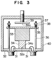
- Figure 3 is a sectional view of a dielectric resonator device according to a third embodiment of the present invention.
- a loop-like electrode 31 through which a high-frequency signal is transmitted is attached to a metal baseplate 32, and a dielectric resonator (of cylindrical form) 33 is bonded to a dielectric support 34 by use of glass and, then, the dielectric support 34 is set on the metal baseplate 32 with a concave 34a thereof being fitted on a positioning protrusion 32a formed on the metal baseplate 32.
- a dielectric heat-radiator 35 of a thin plate form (or disc form) is pressed against the dielectric resonator 33 from a surface thereof on the side remote from the surface to which the dielectric support 34 is bonded.
- the dielectric heat-radiator 35 is fixed to support columns 36 by means of nuts and springs 38, one end of each support column 36 being fixed to the metal baseplate 32.
- a metal case (of cylindrical form) 40 attached with a tuning screw 39 having a plate (disc-shaped) end 39a is mounted on the metal baseplate 32 so as to cover and shield the inside of the case in its entirety.
- the tuning screw 39 is so arranged that the plate end 39a is opposed to the contact surface between the dielectric heat-radiator 35 and the dielectric resonator 33, for adjusting the frequency by processing the electromagnetic energy transmitted through the dielectric thin plate heat-radiator 35.
- the dielectric thin plate heat-sinker 35 is preferably made of alumina, magnesia and the like.
- the dielectric heat-radiator can be completely prevented from being damaged.
Abstract
Description
- This invention relates to a dielectric resonator device used mainly in high-power high-frequency radio equipments.
- Heretofore, the dielectric resonator device has been often used in high-frequency radio equipments as a resonator which has a high Q factor not only in the microwave band but also in the UHF band.
- A conventional dielectric resonator device is constructed such that a cylindrical dielectric resonator to which a dielectric support is bonded with the use of glass is fixed within a metal case provided with a loop-like electrode loop through which high-frequency signals are received and delivered, by screwing the dielectric support, and an opening of the metal case is closed by a metal cover having a tuning screw so as to shield the device. The dielectric resonator is magnetically combined with the loop-like electrode so as to resonate at a specific frequency determined by the dielectric constant, the shape and the type of resonance mode to be used for the resonator. Adjustment of the resonance frequency is performed by moving the tuning screw to and away from the dielectric resonator. It is possible to reduce the size of the dielectric resonator device by increasing the dielectric constant of the resonator.
- On the other hand, it is possible to make the dielectric resonator device operate as a band-pass filter by providing two electrodes which serve as input/output terminals, respectively. The filter of such construction is widely used as the channel filter of the transmitter multiplexer equipped in the mobile radio base station as shown in the literature, for example (K. Wakino, et al., "800 MHz band miniaturized channel dropping filter using low loss dielectric resonator", Denshi Tokyo No. 24, 1985, pp. 72-75).
- In the dielectric resonator device, electromagnetic energy for resonation is stored inside the dielectric resonator and in the vicinity thereof. For this reason, when a metal conductor is brought close to the dielectric resonator, high-frequency current flows on the surface of the conductor so as to cause a loss in electromagnetic energy due to resistance, thereby deteriorating the characteristics of the resonator. Therefore, it is necessary to consider that the internal structure of the metal case of the dielectric resonator device is so designed as not to allow any metal to approach the dielectric resonator to cause the loss of electromagnetic energy.
- Further, part of the electromagnetic energy stored inside and in the vicinity of the dielectric resonator is converted into heat within the dielectric resonator and the dielectric support due to a dielectric loss. The dielectric support is made of a material which has a small dielectric constant and causes less high-frequency loss, and it is designed that most of the electromagnetic energy is stored in the dielectric resonator which exhibits a large dielectric constant so that the dielectric loss is almost caused in the dielectric resonator.
- Heat generated in the dielectric resonator is radiated by way of the following two routes. One of them is to radiate heat from the dielectric support due to heat conduction, and the other one is to radiate heat from the surface of the dielectric resonator through the air within the metal case. However, in addition to the above conditions, there is a certain condition in selecting the material of the dielectric support such that the coefficient of thermal expansion of the material must be identical with that of the dielectric resonator because they are bonded to each other by use of glass. Any of the dielectric materials of high heat conductivity which are known at present cannot satisfy these conditions. In consequence, in the dielectric resonator of the conventional structure, the amount of heat radiated from the dielectric support was very small. Further, in such a case that the dielectric resonator is reduced in size while the dielectric constant or working frequency thereof is increased, it becomes difficult to radiate heat from the surface of the dielectric resonator since the surface area thereof is small.
- In the dielectric resonator device of such construction, when a high-power high-frequency signal is fed thereto, the temperature of the dielectric resonator rises to cause the problems including an increase in high-frequency loss and a drift of resonance frequency of the dielectric resonator.
- In order to solve the above-mentioned problems, there has hitherto been proposed a method in which bar dielectrics are inserted into a drum dielectric resonator from above and below and fixed thereto so as to radiate heat as disclosed in Japanese patent Unexamined publication No. 1-109802. This method, however, has the problems that dimensional accuracy of the drum dielectric resonator and the bar dielectrics and the roughness of the contact surface make it difficult to reduce the contact thermal resistance and that it is impossible to extend the frequency variable range since the tuning mechanism and the resonator cannot be opposed to each other from the viewpoint of structure, in addition to the problem that it is not applicable to the cylindrical dielectric resonator.
- An object of the present invention is to provide a small type dielectric resonator device which can be used at a high power and radiate heat with a high degree of efficiency from a dielectric resonator without deteriorating high-frequency characteristics of the resonator device when it receives a high-power high-frequency signal.
- To this end, according to the present invention, there is provided a dielectric resonator device in which a dielectric radiator is pressed against a dielectric resonator on the side remote from a surface to which a dielectric support is bonded. Preferably, a dielectric heat-radiator of a thin plate form is pressed against the dielectric resonator and is supported elastically with nuts and springs to support columns which are fixed to a metal baseplate at one end thereof. Further the frequency is adjusted by processing the electromagnetic energy transmitted through the dielectric heat-radiator.
- With this arrangement, heat generated from the dielectric resonator propagates through the wide contact surface to the dielectric heat-radiator of high heat conductivity, resulting in that a temperature rise of the dielectric resonator can be retained.
-
- Figure 1 is a sectional view illustrating a dielectric resonator device according to a first embodiment of the present invention;
- Figure 2 is a sectional view illustrating a dielectric resonator device according to a second embodiment of the invention; and
- Figure 3 is a sectional view illustrating a dielectric resonator device according to a third embodiment of the invention.
- Figure 1 is a sectional view of a dielectric resonator device in a first embodiment of the present invention.
- Referring to Figure 1 loop-like electrodes 11 through which a high-frequency signal is received and delivered are disposed within a metal case (of cylindrical form) 12, and a dielectric resonator (of cylindrical form) 13 is bonded to a dielectric support 14) by use of glass and, then, the
dielectric support 14 is fixed within themetal case 12 by fastening ascrew 19. A columnar dielectric heat-radiator 15 is pressed against a surface of thedielectric resonator 13 on the side remote from the surface to which thedielectric support 14 is bonded and, then, fixed by means of ascrew 16 or the like. An opening in themetal case 12 is closed by a metal cover 18 attached with a tuning screw 17 so as to shield the inside of the case in its entirety. - Heat generated caused by a dielectric loss of the
dielectric resonator 13 upon delivery of a high-power high-frequency signal is radiated through the contact surface between thedielectric resonator 13 and the dielectric heat-radiator 15 due to heat conduction. With the above construction, it is easy to obtain a large area of the contact surface between thedielectric resonator 13 and the dielectric heat-radiator 15 as well as to reduce the thermal contact resistance by polishing the contact surfaces. Since the force by which the dielectric heat-radiator 15 is pressed against thedielectric resonator 13 is not applied as tensile force but as pressing force to the glass-bonded portion between thedielectric resonator 13 and thedielectric support 14, there is no possibility of damage of the glass-bonded portion even if the pressing force is increased. In consequence, it is possible to stably maintain a small thermal contact resistance between thedielectric resonator 13 and the dielectric heat-radiator 15 and the mechanical strength can be increased as well. - Figure 2 is a sectional view illustrating a dielectric resonator device in a second embodiment of the present invention.
- In Figure 2, loop-
like electrodes 21 through which a high-frequency signal is received and delivered are disposed within the metal case (of cylindrical form) 12, and a columnardielectric resonator 23 is bonded, to a columnardielectric support 24 by use of glass and, then thedielectric support 24 is fixed within themetal case 12 by fastening ascrew 29. A dielectric heat-radiator 25 of a thin plate form (or a disc form) is pressed against a surface of thedielectric resonator 23 on the side remote from the surface to which thedielectric support 24 is bonded and, then, fixed by means ofscrews 26a andattachment 26b. An opening in themetal case 12 is closed by ametal cover 28 attached thereto with atuning screw 27 having an end plate (disc-shaped) 27a, so as to shield the inside of the case in its entirety. Thetuning screw 27 is so arranged as to be opposed to the contact surface between the dielectric heat-sinker 25 and thedielectric resonator 23 for serving to adjust the frequency by processing the electromagnetic energy transmitted through the dielectric thin plate heat-radiator 25. - In this embodiment, since the frequency is adjusted by processing the electromagnetic energy transmitted through the dielectric thin plate heat-
radiator 25, it is possible to obtain a large area through which the plate end 27a of thetuning screw 27 faces thedielectric resonator 23. It is therefore possible to enlarge the frequency variable range in comparison with the first embodiment. - The fundamental principle of the frequency adjusting method of this embodiment, that is, the idea of processing the electromagnetic energy transmitted through the dielectric plate has been already disclosed in the U.S. Patent (USP 4628283) as a method of shielding an oscillator using a dielectric resonator. However, the method of fixing the dielectric resonator has offered a critical problem in the high-power dielectric resonator device, which is solved by the present invention, the above-mentioned U.S. Patent neither discloses nor suggests the method of fixing the dielectric resonator which is available at a high electric power. For example, a method of bonding the dielectric resonator and the dielectric plate to each other by a resinous adhesive cannot be used because the resin of the adhesive is deteriorated by the high-frequency signal, and therefore, the above mentioned U.S. Patent cannot solve this problem. In the present invention, the above-described principle is applied to the original fixing method that the dielectric plate heat-radiator is pressed against a surface of the dielectric resonator on the side remote from the surface to which the dielectric support is bonded.
- Further, in the present embodiment, since the dielectric heat-radiator which is to be pressed against the dielectric resonator is formed in the shape of a thin plate and hence has a small volume a part of the electromagnetic energy expected to be stored in the dielectric resonator, that is, the electromagnetic energy expected to exist within the dielectric heat radiator, can be remarkably reduced in capacity as compared with the case of the first embodiment. As a result, a loss of dielectromagnetic energy due to a dielectric loss of the electric heat-radiator can be reduced and, at the same time, the difference between the resonance frequency obtained when the dielectric resonator is used alone and the resonance frequency obtained when the dielectric resonator is used in contact with the dielectric heat-radiator as well as the difference between the temperature coefficients of the resonance frequencies of the respective cases can be reduced and therefore, it is possible to facilitate the design of the dielectric resonator.
- In addition, although the dielectric heat radiator is decreased in size since it is formed in the shape of plate, the area of the contact surface which is one of factors determining the thermal contact resistance between the dielectric heat-radiator and the dielectric resonator remains unchanged, and therefore, the radiation characteristic is not deteriorated. In consequence, the thickness of the dielectric heat-radiator can be made thinner so far as the thermal resistivity does not become a problem.
- Figure 3 is a sectional view of a dielectric resonator device according to a third embodiment of the present invention.
- Referring to Figure 3, a loop-
like electrode 31 through which a high-frequency signal is transmitted is attached to ametal baseplate 32, and a dielectric resonator (of cylindrical form) 33 is bonded to adielectric support 34 by use of glass and, then, thedielectric support 34 is set on themetal baseplate 32 with a concave 34a thereof being fitted on apositioning protrusion 32a formed on themetal baseplate 32. A dielectric heat-radiator 35 of a thin plate form (or disc form) is pressed against thedielectric resonator 33 from a surface thereof on the side remote from the surface to which thedielectric support 34 is bonded. The dielectric heat-radiator 35 is fixed to supportcolumns 36 by means of nuts andsprings 38, one end of eachsupport column 36 being fixed to themetal baseplate 32. A metal case (of cylindrical form) 40 attached with atuning screw 39 having a plate (disc-shaped)end 39a is mounted on themetal baseplate 32 so as to cover and shield the inside of the case in its entirety. Thetuning screw 39 is so arranged that theplate end 39a is opposed to the contact surface between the dielectric heat-radiator 35 and thedielectric resonator 33, for adjusting the frequency by processing the electromagnetic energy transmitted through the dielectric thin plate heat-radiator 35. The result of experiments shows that the dielectric thin plate heat-sinker 35 is preferably made of alumina, magnesia and the like. - In the second embodiment, although the difference between the thermal expansion of the dielectric resonator and the dielectric support and the thermal expansion of the support columns is absorbed through the deflection of the dielectric heat-radiator, the strength thereof is not high. However in this third embodiment, since the difference in thermal expansion is absorbed by using the
springs 38, the dielectric heat-radiator can be completely prevented from being damaged. - Further, according to this embodiment, since attaching of the dielectric heat-radiator can be carried out in the state where the metal case is removed, it is possible to eliminate defective in manufacturing by visibly confirming the state of contact between the dielectric resonator and the dielectric heat-sinker.
Claims (4)
- A dielectric resonator device comprising:
a metal case provided with an electrode through which a high-frequency signal is transmitted;
a dielectric resonator one surface of which is bonded to a dielectric support fixed in said metal case;
a dielectric heat-radiator pressed against a surface of said dielectric resonator on the side remote from said one surface to which said dielectric support is bonded; and
a metal cover having a tuning screw and serving to close an opening of said metal case. - A dielectric resonator device comprising:
a metal case provided with an electrode through which a high-frequency signal is transmitted
a dielectric resonator one surface of which is bonded to a dielectric support fixed in said metal case;
a dielectric heat-sinker of a thin plate form pressed against a surface of said dielectric resonator on the side remote from said one surface to which said dielectric support is bonded; and
a metal cover having a tuning member and serving to close an opening of said metal case,
wherein said tuning member is arranged opposite to the contact surface between said dielectric heat-radiator and said dielectric resonator so as to adjust the frequency by processing on the electromagnetic energy transmitted through said dielectric heat-sinker. - A dielectric resonator device comprising:
a metal baseplate provided with an electrode through which a high-frequency signal enters and leaves;
a dielectric resonator one surface of which is bonded to a dielectric support located in position on said metal baseplate;
a dielectric heat-radiator of a thin plate form pressed against a surface of said dielectric resonator on the side remote from said one surface to which said dielectric support is bonded, said dielectric heat-radiator being supported elastically with nuts and springs by support columns each fixed to said metal baseplate at one end thereof; and
a metal case having at tuning member and mounted on said metal baseplate so as to cover the dielectric resonator in its entirety,
wherein said tuning member is arranged opposite to the contact surface between said dielectric heat-radiator and said dielectric resonator so as to adjust the frequency by processing the electromagnetic energy transmitted through said dielectric heat-sinker. - A dielectric resonator device according to Claim 3, wherein the dielectric heat-radiator is made of a material selected from a group consisting of alumina, magnesia, and the like.
Applications Claiming Priority (6)
| Application Number | Priority Date | Filing Date | Title |
|---|---|---|---|
| JP258022/90 | 1990-09-26 | ||
| JP25802390 | 1990-09-26 | ||
| JP258023/90 | 1990-09-26 | ||
| JP25802290 | 1990-09-26 | ||
| JP33998/91 | 1991-02-28 | ||
| JP3399891 | 1991-02-28 |
Publications (2)
| Publication Number | Publication Date |
|---|---|
| EP0477925A1 true EP0477925A1 (en) | 1992-04-01 |
| EP0477925B1 EP0477925B1 (en) | 1996-03-06 |
Family
ID=27288283
Family Applications (1)
| Application Number | Title | Priority Date | Filing Date |
|---|---|---|---|
| EP91116372A Expired - Lifetime EP0477925B1 (en) | 1990-09-26 | 1991-09-25 | Dielectric resonator device |
Country Status (3)
| Country | Link |
|---|---|
| US (1) | US5221913A (en) |
| EP (1) | EP0477925B1 (en) |
| DE (1) | DE69117633T2 (en) |
Cited By (2)
| Publication number | Priority date | Publication date | Assignee | Title |
|---|---|---|---|---|
| ITTO20110835A1 (en) * | 2011-09-20 | 2013-03-21 | Ac Consulting | KU RESONATING FILTER AND CAVITY IN KU AND BEYOND APPLICATIONS FOR INPUT DEMULTIPLATION |
| EP3145022A1 (en) * | 2015-09-15 | 2017-03-22 | Spinner GmbH | Microwave rf filter with dielectric resonator |
Families Citing this family (5)
| Publication number | Priority date | Publication date | Assignee | Title |
|---|---|---|---|---|
| US5515016A (en) * | 1994-06-06 | 1996-05-07 | Space Systems/Loral, Inc. | High power dielectric resonator filter |
| US6208227B1 (en) * | 1998-01-19 | 2001-03-27 | Illinois Superconductor Corporation | Electromagnetic resonator |
| JP2000295005A (en) * | 1999-04-09 | 2000-10-20 | Murata Mfg Co Ltd | Dielectric filter, duplexer and communication equipment |
| AUPQ487799A0 (en) * | 1999-12-23 | 2000-02-03 | Poseidon Scientific Instruments Pty Ltd | Multi-layer microwave resonator |
| CN104009276A (en) * | 2013-02-25 | 2014-08-27 | 中兴通讯股份有限公司 | Dielectric resonator, assembly method and dielectric filter |
Citations (6)
| Publication number | Priority date | Publication date | Assignee | Title |
|---|---|---|---|---|
| FR2284200A1 (en) * | 1974-09-06 | 1976-04-02 | Murata Manufacturing Co | HYPERFREQUENCY DIELECTRIC RESONATOR |
| US4028643A (en) * | 1976-05-12 | 1977-06-07 | University Of Illinois Foundation | Waveguide having strip dielectric structure |
| US4580116A (en) * | 1985-02-11 | 1986-04-01 | The United States Of America As Represented By The Secretary Of The Army | Dielectric resonator |
| US4667172A (en) * | 1986-04-07 | 1987-05-19 | Motorola, Inc. | Ceramic transmitter combiner with variable electrical length tuning stub and coupling loop interface |
| EP0351840A2 (en) * | 1988-07-21 | 1990-01-24 | CSELT Centro Studi e Laboratori Telecomunicazioni S.p.A. | Dielectric-loaded cavity resonator |
| DE3928015A1 (en) * | 1988-08-24 | 1990-03-08 | Murata Manufacturing Co | DIELECTRIC FILTER |
Family Cites Families (7)
| Publication number | Priority date | Publication date | Assignee | Title |
|---|---|---|---|---|
| IT1123841B (en) * | 1979-10-15 | 1986-04-30 | Telettra Lab Telefon | MICROWAVES CAVITY STABILIZED IN TEMPERATURE AND FREQUENCY ADJUSTABLE |
| JPS5881304A (en) * | 1981-11-11 | 1983-05-16 | Nippon Telegr & Teleph Corp <Ntt> | Dielectric resonator |
| US4628283A (en) * | 1983-11-07 | 1986-12-09 | The Narda Microwave Corporation | Hermetically sealed oscillator with dielectric resonator tuned through dielectric window by adjusting screw |
| JPS60112301A (en) * | 1983-11-22 | 1985-06-18 | Nec Corp | High frequency oscillator |
| JPH01109802A (en) * | 1987-10-22 | 1989-04-26 | Nippon Dengiyou Kosaku Kk | Dielectric resonator |
| US4922211A (en) * | 1988-04-15 | 1990-05-01 | Siemens Aktiengesellschaft | Microwave oscillator in which the dielectric resonator is hermetically sealed |
| US4963841A (en) * | 1989-05-25 | 1990-10-16 | Raytheon Company | Dielectric resonator filter |
-
1991
- 1991-09-09 US US07/756,584 patent/US5221913A/en not_active Expired - Lifetime
- 1991-09-25 EP EP91116372A patent/EP0477925B1/en not_active Expired - Lifetime
- 1991-09-25 DE DE69117633T patent/DE69117633T2/en not_active Expired - Lifetime
Patent Citations (6)
| Publication number | Priority date | Publication date | Assignee | Title |
|---|---|---|---|---|
| FR2284200A1 (en) * | 1974-09-06 | 1976-04-02 | Murata Manufacturing Co | HYPERFREQUENCY DIELECTRIC RESONATOR |
| US4028643A (en) * | 1976-05-12 | 1977-06-07 | University Of Illinois Foundation | Waveguide having strip dielectric structure |
| US4580116A (en) * | 1985-02-11 | 1986-04-01 | The United States Of America As Represented By The Secretary Of The Army | Dielectric resonator |
| US4667172A (en) * | 1986-04-07 | 1987-05-19 | Motorola, Inc. | Ceramic transmitter combiner with variable electrical length tuning stub and coupling loop interface |
| EP0351840A2 (en) * | 1988-07-21 | 1990-01-24 | CSELT Centro Studi e Laboratori Telecomunicazioni S.p.A. | Dielectric-loaded cavity resonator |
| DE3928015A1 (en) * | 1988-08-24 | 1990-03-08 | Murata Manufacturing Co | DIELECTRIC FILTER |
Cited By (4)
| Publication number | Priority date | Publication date | Assignee | Title |
|---|---|---|---|---|
| ITTO20110835A1 (en) * | 2011-09-20 | 2013-03-21 | Ac Consulting | KU RESONATING FILTER AND CAVITY IN KU AND BEYOND APPLICATIONS FOR INPUT DEMULTIPLATION |
| WO2013042058A1 (en) * | 2011-09-20 | 2013-03-28 | Ac Consulting | Filter and resonant cavity at ku-band and above for imux applications |
| EP3145022A1 (en) * | 2015-09-15 | 2017-03-22 | Spinner GmbH | Microwave rf filter with dielectric resonator |
| US10862183B2 (en) | 2015-09-15 | 2020-12-08 | Spinner Gmbh | Microwave bandpass filter comprising a conductive housing with a dielectric resonator therein and including an internal coupling element providing coupling between HEEx and HEEy modes |
Also Published As
| Publication number | Publication date |
|---|---|
| US5221913A (en) | 1993-06-22 |
| DE69117633T2 (en) | 1996-10-02 |
| DE69117633D1 (en) | 1996-04-11 |
| EP0477925B1 (en) | 1996-03-06 |
Similar Documents
| Publication | Publication Date | Title |
|---|---|---|
| US4646038A (en) | Ceramic resonator filter with electromagnetic shielding | |
| EP0877435B1 (en) | Dielectric resonator, dielectric notch filter, and dielectric filter | |
| US6002311A (en) | Dielectric TM mode resonator for RF filters | |
| US4667172A (en) | Ceramic transmitter combiner with variable electrical length tuning stub and coupling loop interface | |
| US6933811B2 (en) | Resonator and high-frequency filter | |
| US5200721A (en) | Dual-mode filters using dielectric resonators with apertures | |
| US4489293A (en) | Miniature dual-mode, dielectric-loaded cavity filter | |
| EP0064799A1 (en) | Miniature dual-mode, dielectric-loaded cavity filter | |
| US6297715B1 (en) | General response dual-mode, dielectric resonator loaded cavity filter | |
| US5221913A (en) | Dielectric resonator device with thin plate type dielectric heat-radiator | |
| US6812800B2 (en) | Atomic oscillator | |
| EP1079457B1 (en) | Dielectric resonance device, dielectric filter, composite dielectric filter device, dielectric duplexer, and communication apparatus | |
| JP2514324B2 (en) | Radio frequency filter with temperature-compensated ceramic resonator | |
| US4613833A (en) | Transmission channel coupler for antenna | |
| US6255919B1 (en) | Filter utilizing a coupling bar | |
| US4570137A (en) | Lumped-mode resonator | |
| GB2188789A (en) | R.F. ceramic resonator filter; microstrip combiner | |
| EP0917239B1 (en) | Filter, duplexer and communication device | |
| US6225879B1 (en) | Unperturbed ring resonator with an odd overtone vibration mode | |
| CA2462330C (en) | Dielectric resonator filter | |
| JPH0522008A (en) | Dielectric resonator | |
| CA2252364C (en) | Filter, duplexer, and communication device | |
| JPH0794918A (en) | Waveguide type resonator device | |
| JPS63136801A (en) | Band pass filter device for polarized type dielectric resonator | |
| JPS60145702A (en) | Dielectric filter |
Legal Events
| Date | Code | Title | Description |
|---|---|---|---|
| PUAI | Public reference made under article 153(3) epc to a published international application that has entered the european phase |
Free format text: ORIGINAL CODE: 0009012 |
|
| AK | Designated contracting states |
Kind code of ref document: A1 Designated state(s): DE FR GB SE |
|
| 17P | Request for examination filed |
Effective date: 19920526 |
|
| 17Q | First examination report despatched |
Effective date: 19940518 |
|
| GRAH | Despatch of communication of intention to grant a patent |
Free format text: ORIGINAL CODE: EPIDOS IGRA |
|
| GRAA | (expected) grant |
Free format text: ORIGINAL CODE: 0009210 |
|
| AK | Designated contracting states |
Kind code of ref document: B1 Designated state(s): DE FR GB SE |
|
| REF | Corresponds to: |
Ref document number: 69117633 Country of ref document: DE Date of ref document: 19960411 |
|
| ET | Fr: translation filed | ||
| PLBE | No opposition filed within time limit |
Free format text: ORIGINAL CODE: 0009261 |
|
| STAA | Information on the status of an ep patent application or granted ep patent |
Free format text: STATUS: NO OPPOSITION FILED WITHIN TIME LIMIT |
|
| 26N | No opposition filed | ||
| REG | Reference to a national code |
Ref country code: GB Ref legal event code: IF02 |
|
| PGFP | Annual fee paid to national office [announced via postgrant information from national office to epo] |
Ref country code: SE Payment date: 20100913 Year of fee payment: 20 Ref country code: FR Payment date: 20100921 Year of fee payment: 20 |
|
| PGFP | Annual fee paid to national office [announced via postgrant information from national office to epo] |
Ref country code: GB Payment date: 20100922 Year of fee payment: 20 |
|
| PGFP | Annual fee paid to national office [announced via postgrant information from national office to epo] |
Ref country code: DE Payment date: 20100922 Year of fee payment: 20 |
|
| REG | Reference to a national code |
Ref country code: DE Ref legal event code: R071 Ref document number: 69117633 Country of ref document: DE |
|
| REG | Reference to a national code |
Ref country code: DE Ref legal event code: R071 Ref document number: 69117633 Country of ref document: DE |
|
| REG | Reference to a national code |
Ref country code: GB Ref legal event code: PE20 Expiry date: 20110924 |
|
| REG | Reference to a national code |
Ref country code: SE Ref legal event code: EUG |
|
| PG25 | Lapsed in a contracting state [announced via postgrant information from national office to epo] |
Ref country code: GB Free format text: LAPSE BECAUSE OF EXPIRATION OF PROTECTION Effective date: 20110924 |
|
| PG25 | Lapsed in a contracting state [announced via postgrant information from national office to epo] |
Ref country code: DE Free format text: LAPSE BECAUSE OF EXPIRATION OF PROTECTION Effective date: 20110926 |