EP0477619A1 - Apparatus and method for subcuticular stapling of body tissue - Google Patents
Apparatus and method for subcuticular stapling of body tissue Download PDFInfo
- Publication number
- EP0477619A1 EP0477619A1 EP91115017A EP91115017A EP0477619A1 EP 0477619 A1 EP0477619 A1 EP 0477619A1 EP 91115017 A EP91115017 A EP 91115017A EP 91115017 A EP91115017 A EP 91115017A EP 0477619 A1 EP0477619 A1 EP 0477619A1
- Authority
- EP
- European Patent Office
- Prior art keywords
- elongate
- body tissue
- skin
- portions
- rod
- Prior art date
- Legal status (The legal status is an assumption and is not a legal conclusion. Google has not performed a legal analysis and makes no representation as to the accuracy of the status listed.)
- Granted
Links
Images


Classifications
-
- A—HUMAN NECESSITIES
- A61—MEDICAL OR VETERINARY SCIENCE; HYGIENE
- A61B—DIAGNOSIS; SURGERY; IDENTIFICATION
- A61B17/00—Surgical instruments, devices or methods, e.g. tourniquets
- A61B17/064—Surgical staples, i.e. penetrating the tissue
-
- A—HUMAN NECESSITIES
- A61—MEDICAL OR VETERINARY SCIENCE; HYGIENE
- A61B—DIAGNOSIS; SURGERY; IDENTIFICATION
- A61B17/00—Surgical instruments, devices or methods, e.g. tourniquets
- A61B17/04—Surgical instruments, devices or methods, e.g. tourniquets for suturing wounds; Holders or packages for needles or suture materials
-
- A—HUMAN NECESSITIES
- A61—MEDICAL OR VETERINARY SCIENCE; HYGIENE
- A61B—DIAGNOSIS; SURGERY; IDENTIFICATION
- A61B17/00—Surgical instruments, devices or methods, e.g. tourniquets
- A61B17/068—Surgical staplers, e.g. containing multiple staples or clamps
-
- A—HUMAN NECESSITIES
- A61—MEDICAL OR VETERINARY SCIENCE; HYGIENE
- A61B—DIAGNOSIS; SURGERY; IDENTIFICATION
- A61B17/00—Surgical instruments, devices or methods, e.g. tourniquets
- A61B17/28—Surgical forceps
- A61B17/2812—Surgical forceps with a single pivotal connection
- A61B17/282—Jaws
-
- A—HUMAN NECESSITIES
- A61—MEDICAL OR VETERINARY SCIENCE; HYGIENE
- A61B—DIAGNOSIS; SURGERY; IDENTIFICATION
- A61B17/00—Surgical instruments, devices or methods, e.g. tourniquets
- A61B17/56—Surgical instruments or methods for treatment of bones or joints; Devices specially adapted therefor
- A61B17/58—Surgical instruments or methods for treatment of bones or joints; Devices specially adapted therefor for osteosynthesis, e.g. bone plates, screws, setting implements or the like
- A61B17/68—Internal fixation devices, including fasteners and spinal fixators, even if a part thereof projects from the skin
-
- A—HUMAN NECESSITIES
- A61—MEDICAL OR VETERINARY SCIENCE; HYGIENE
- A61B—DIAGNOSIS; SURGERY; IDENTIFICATION
- A61B17/00—Surgical instruments, devices or methods, e.g. tourniquets
- A61B17/064—Surgical staples, i.e. penetrating the tissue
- A61B2017/0641—Surgical staples, i.e. penetrating the tissue having at least three legs as part of one single body
Definitions
- the present invention relates to an apparatus and method for subcuticular attachment of skin surrounding an opening wherein the opening is either caused unintentionally or by surgical procedure.
- subcutaneous sutures In handling tissue for attaching the surgical ends adjacent an opening, care must be taken in attaching the open ends to provide a minimum of the usual well-known telltale marks in the skin. For example, the application of sutures in cutaneous surgery will often result in the appearance of telltale crosshatch markings, whereas the use of sutures subcutaneously allows for early removal to minimize the telltale marks.
- Application of subcutaneous sutures generally refers to introduction of sutures at well below the epidermis and dermis.
- Subcuticular sutures generally refer to sutures introduced beneath the epidermis. In any event, reference to attachment of cutaneous matter below the epidermis at any level is sometimes referred to as "subcutaneous".
- Surgically attaching cutaneous matter is also accomplished by application of staples which are generally of a metal material and are closed by action against an anvil which causes the ends of the staple to close after piercing the skin surrounding an opening.
- staples which are generally of a metal material and are closed by action against an anvil which causes the ends of the staple to close after piercing the skin surrounding an opening.
- the portions of skin are first drawn together and then stapled or sutured so as to hold them together until natural healing takes place.
- the steps are often cumbersome to the surgeon since holding the skin together requires one motion and stapling or suturing requires another.
- a surgical apparatus for attaching at least two adjacent end portions of a medium such as cutaneous body tissue which comprises a pair of jaws, means for moving the jaws toward and away from each other, and body tissue engaging means extending from each jaw and facing the opposed jaw and adapted to engage the respective opposed portions of the medium such that when the jaws are moved toward each other said engaging means causes the two end portions of the medium to be displaced toward each other and to assume an irregular or undulating shape whereby an elongated member may be directed generally medially of the medium to thereby attach opposed portions of the medium.
- a medium such as cutaneous body tissue
- each jaw includes a sharp pointed member positioned for engagement with marginal end portions of skin adjacent an opening therein such that when the jaws are displaced toward each other, the skin portions move toward each other and into engagement and assume an undulating configuration at the interface therebetween.
- the apparatus further comprises a cartridge positioned adjacent the jaws and adapted to support a plurality of elongated skin attaching members.
- Each skin attaching member is preferably a rod-like member having a sharp pointed tip at the distal end to facilitate subcuticular penetration of the skin.
- each rod-like member is circular in cross section and may include at least one slot extending at least partially around a peripheral portion thereof.
- the rod-like members are substantially rectangular in cross section. Indentations may also be formed in the rods to improve retention in the tissue. This facilitates manufacture of the rods, improves feeding of the rods and increases their retention characteristics.
- the cartridge is adapted to contain a plurality of the rod-like members and includes means to resiliently bias the rod-like members toward a position for advancing the member distally toward the body tissue when the body tissue is gripped by the sharp pointed members.
- the members are of length sufficient to engage oppositely sloped skin portions as determined by the dimensions and relative spacing of the pointed tips.
- the rod-like members may include means on the outer surface to retain them in position within the body tissue.
- a method for attaching two adjacent end portions of skin surrounding an opening comprising gripping one marginal end portion of the skin adjacent the opening at two spaced locations, gripping the opposite marginal end portion of the skin at a location generally medial of the two locations at which the first marginal end portion is gripped, displacing the two end portions of skin surrounding the opening toward each other sufficient to cause the end portions to engage each other and to assume an undulating shape, and introducing an elongated staple into the end portions of the skin subcuticularly, the elongated staple being of length sufficient to penetrate at least two spaced portions of skin on the same side of the opening so as to retain the marginal end portions together in end to end contacting relation to promote healing.
- the method may comprise configuring the staple to have an irregular outer surface to prevent the staple from working itself out of the subcuticular region.
- Various configurations of the staple are also contemplated.
- the method is practiced utilizing sharp skin engaging members attached to jaws as described to permit gripping the skin and bringing the end portions adjacent an opening to form the undulating shape.
- the staple may also be inserted subcutaneously.
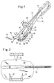
- Fig. 1 illustrates the apparatus 10 for subcuticular stapling of skin, constructed according to the present invention.
- the apparatus 10 includes elongated arms 12 and 14 connected as shown by end bracket 16 and resiliently biased away from each other.
- the resilient outward bias may be provided naturally by fabricating the arms 12 and 14 of a resilient material such as spring steel, or optionally may be provided by incorporating a separate resilient spring in region of connecting bracket 16.
- each arm is constructed as shown.
- Arm 12 includes an extension or jaw 18 oriented at an appropriate obtuse angle with respect to the main portion of the arm and arm 14 includes a similar extension or jaw 20 as shown.
- the extension 20 includes sharp pointed skin gripping tips 22,24 spaced apart from each other and extending generally downwardly and toward extension 18.
- Extension 18 includes a similarly shaped skin gripping tip 26 oriented generally downwardly and extending toward extension 20.
- the position of skin gripping tip 26 on extension 18 is preferably such as to be located medially between skin gripping tips 22, 24 when the arms 12 and 14 are manually brought together to grip the skin surrounding an opening as will be described.
- Each skin gripping tip 26, 22, 24 includes a broad base area to facilitate grasping the skin with minimum cutting after the sharp tip has penetrated the surface. Alternatively, a different number of skin gripping tips could be provided on each arm.
- Fig. 2 the basic operative principles of the invention will be described.
- the apparatus is positioned such that extensions 18,20 may be positioned in contact with, and generally parallel to the upper surface of the skin.
- extensions 18,20 may be positioned in contact with, and generally parallel to the upper surface of the skin.
- the extensions are advanced downwardly against the skin sufficient to cause piercing tips 22, 24 and 26 to pierce the skin minimally as shown.
- the arms 12, 14 are squeezed together by the surgeon to cause the three sharp tips to join the skin portions surrounding the opening as shown in Fig. 3, i.e. to assume an undulating, or sinusoidal shape.
- the staple actuating mechanism 32 is fired to cause the elongated staple 34 to penetrate the tissue below the upper epidermal layer and to retain the separate portions of skin in interfacial engaged relation as shown in Fig. 4.
- the opening in the skin is prepared for natural permanent healing and adhesion with minimum or no scarring.
- Fig. 5 there is illustrated a cross-sectional view taken along lines 5-5 of Fig. 4, showing the sharp tips 26, 22 and 24 in position securing the skin surrounding the opening 30 with staple 34 fired in position.
- the inward pressure on arms 12, 14 of the apparatus may be relieved to permit them to be opened by the resilient spring action and the sharp tips may be removed from the skin.
- one or more of the staples may be fired in sequence and in adjacent end to end relation sufficient to maintain the opening in closed condition to promote healing.
- the staple according to the invention is preferably constructed as a sharp tipped elongated member of naturally bioabsorbable material such as synthetic polymers or copolymers possessing a significant number of short-chain polyester linkages or other readily hydrolyzable linkages in their structure as, for example, is the case with polyglycolic acid, lactide-glycolide polymers, polydioxanone, polyalkylene glycols, polytrimethylene carbonate, polycaprolactone, their copolymers and related materials.
- One preferred material is made of a copolymer of lactide and glycolide made from approximately 90% m glycolide and approximately 10% m lactide.
- Another bioabsorbable material is made of a copolymer of lactide and glycolide made from approximately 25% m glycolide and approximately 75% m lactide blended with a homopolymer of polyglycolide so that the total composition is composed of approximately 42% glycolide.
- Other bioabsorbable materials for constructing the staple are disclosed in U.S. Patent No. 4,523,591 to Kaplan et al. and U.S. Patent No. 4,744,365 to Kaplan et al., herein incorporated by reference.
- the fastening member is in the form of a rod or pin having a generally circular cross-section and must be of length at least sufficient to extend over at least two oppositely sloped surfaces of the skin on one side of the opening in order to prevent the staple from readily working its way out of the skin.
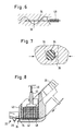
- the staple preferably includes up to five or more slots 36 spaced along the length thereof to provide an irregular surface in engagement with the skin. This provides further stability to the staple and assists in preventing the staple from working its way out of the skin while retaining its rod-like configuration after application.
- the slots 36 may extend partially around the staple as shown in cross-section in Fig.
- the slots 36 extend approximately between the 2 o'clock and 5 o'clock positions and the 7 o'clock and 10 o'clock positions. This feature is particularly significant in view of the undulating shape which the skin assumes at the interface between the two faces of the opening 30, which provides an environment for the rod to otherwise work itself out of the skin when the skin portions are shifted due to motions of the body.
- the staple may be approximately .350 inch in length, have a major outer diameter between .015 and .016 inch and a minor dimension at the slots of between .012 and .013 inch.
- the staple is of length at least equal to the dimension between the sharp skin engaging tips 22,24 on extension 20. Clearly, however, the dimensions may be varied, depending upon the particular application contemplated.
- the circular shaped rod of Figures 5 and 6 is one example of the staple (fastening member) of the present invention which can be utilized to fasten the undulating skin.
- the staple 70 is in the form of a rod or pin which is generally rectangular in cross section. In the illustrated embodiment, it is substantially square in cross section.
- Rod 70 is elongated and of sufficient length to extend over at least two oppositely sloped surfaces of the skin on one side of the opening.
- the tapered tip 72 at the distal end of rod 70 has a sharp point 74 to facilitate penetration through the skin.
- rod 80 is also of substantially square cross section, and has a tapered tip 82 with a sharp point 84.
- the rod 80 includes an indentation 86 adjacent its distal end and an indentation 88 adjacent its proximal end to improve the retention of the rod by restricting proximal and distal movement. That is, since the tissue stretches during penetration of the rod and then retracts, the edge of the indentation will restrict movement. Although only one indentation is shown at each end, clearly additional indentations can be formed along the length to improve retention. The indentations can be formed on opposing surfaces or the identations can extend along all side surfaces. Proximal end surface 87 of rod 80 and proximal end surface 77 of rod 70 are adapted to be contacted directly by a pusher for driving the rod which will be described below.
- the rod is sufficiently rigid to substantially retain its elongated shape upon insertion.
- the rectangular shaped configuration of the rods facilitates stacking of the rods within staple cartridge 40 as described below. This configuration also provides for improved retention within the skin as the rods do not work their way out of the skin as easily as the rounded shaped rods.
- the rods of Figures 9 and 10 also have the advantage in accommodating inaccuracies in molding techniques.
- Line P represents the parting line of the two half molds utilized in forming rods 70 or 80.
- the accuracy of molding the rods of Figures 9 and 10 can be improved by forming the rod with cut edges 90 so that the parting line P for the half molds is located at a non-critical point i.e. along edges 90. That is, the more critical dimensions (e.g. length) of edges 92, 94, 96 and 98 can be maintained substantially constant even if the edges 90 are not aligned as a result of joining the two half molds during formation of the rod. In other words, any variation in the widthwise dimension as a result of misalignment during formation will not significantly vary the length of the more critical edges.
- Cut or flattened edges 90 also provide a smoother surface for the rods 70, 80, thereby preventing cutting of the tissue which might otherwise occur if the junction of edges 92, 94, 96, 98 was a single point as in a perfect square.
- rods are within the scope of the present invention as long as they are sufficiently elongated to penetrate at least one of the undulating portions of the opposing skin areas.
- rods of hexagonal cross section could be provided.
- the dimensions of the rod can vary depending on its use.
- the length of the rod 70 can range from .440 to .445 inches
- the length of each side edge e.g. edges 92, 94, 46 and 98
- the length of edge 90 can range from approximately .0036 to .0056 inches.
- the tapered tip forms a point at an approximate 30 ° angle and the tip portion can have a length ranging from approximately .0653 to .0693 inches.
- the indentation can have a depth of approximately .003 to .004 inches.
- these dimensions are provided solely by way of example as rods of other dimensions are also within the scope of the present invention.
- a staple cartridge which can provide repeated firing of staples subcuticularly into the skin as shown in Fig. 1.
- the apparatus includes a central arm 38 with staple cartridge 40 attached to the lower end.
- the cartridge contains a plurality of staples 34 in vertically stacked relation as shown in Fig. 8, biased downwardly toward the firing chamber 42 by a plunger 44 and resilient spring arrangement 46 shown schematically in Fig. 8.
- the cross-sectional dimension of chamber 42 is equal to or slightly greater than the major diameter of the staple 34 to facilitate a snug fit for the staple in the chamber.
- the length of cartridge 40 and chamber 42 is at least equal to the length of the staples.
- rods 70 and 80 facilitates stacking as they can be stacked along their straight edges.
- Rods 70 can be vertically stacked in a similar fashion as rods 30.
- rods 70 can be diagonally stacked along edge 94. This advantageously conserves space as compared to the vertical stacking of rods 30.
- Rods 80 can be stacked in a similar fashion as rods 70.
- the cartridge would be appropriately configured to accommodate the diagonally stacked rods.
- the firing mechanism includes a staple firing plunger in the form of a flexible plunger wire 48 which is slidable through staple firing chamber 42 to engage the staple next in line to cause it to advance into the skin at a subcuticular level.
- the cross-section of firing wire 48 approximately matches the cross-section of staple 34 or of staple 70 and is attached at the proximal end to rod 50 as shown in Fig. 1, which is slidable within opening 54 in guide housing 56 such that proximal upward movement of rod 50 causes withdrawal of wire 48, and distal downward movement thereof causes firing action by wire 48 on staple 34.
- Staple firing may be accomplished by manual downward distal movement of ring 58 attached to rod 50 as shown by set screw 52.
- Withdrawal of firing wire 48 out of firing chamber 42 is accomplished by manually moving ring 58 (and rod 52) proximally upwardly to permit the next staple 34 to enter the firing chamber 42 under downward action of spring 46. Further guidance for rod 50 is provided by proximally located second external guide housing 60 which contains a second guide opening 62 for reception of rod 50. Thus the two guide housings 56 and 60 serve to firmly position rod 50.
- the firing movements of wire 48 may be adjusted by resetting the position of rod 50 relative to ring 58 by loosening set screw 52 and setting the desired position of rod 50. Further, it is noted that guide openings 54 and 62 are circular in cross-section almost equal to or slightly greater in dimension than rod 50. Sufficient clearance is provided to guide rod 50 yet to maintain steady slidable movement of the rod. Plunger wire 48 has a cross-sectional dimension slightly less than staple firing chamber 42 but sufficient to maintain steady distal and proximal movement therewithin while engaging the proximal end face of the staple.
- the staple 34 and the firing wire 48 are similarly dimensioned in cross-section, at least at the proximal end, such that engagement of the proximal surface of the staple by the wire 48 results in even and steady distal movement of the staple when the wire is advanced distally.
- the apparatus is inserted into the opening in the skin closest to one end with the jaws 18, 20 positioned in respective engagement with the opposed marginal skin portions adjacent the opening.
- the jaws are advanced toward the skin sufficient to cause the sharp tips 26, 22 and 24 to grip the skin by piercing the outer layer or layers.
- the arms 12, 14 are manually drawn together to cause the skin to engage each other and to form an irregular, or undulating shape.
- the staple 34 is fired into the cutaneous matter as shown in Fig. 4 to retain the opposed skin portions together.
- the jaws are then withdrawn from the skin and the procedure is repeated in the area next adjacent the inserted fastener a sufficient number of times to close the entire opening in the skin.
- the structures and embodiments of alternative staple magazines may be utilized in combination with the multiple tip attachment feature which permit subcuticular stapling of an opening in body tissue.
- the preferred embodiment herein contemplates subcuticular attachment of cutaneous matter, it is well within the contemplated invention to apply such staples at subcutaneous levels, ie. below the epidermis and dermis. Such applications would involve minor variations of the dimensional relation between the sharp tips 22,24 and 26 and the staple firing chamber 42.
- a surgical opening or wound in the skin can be stapled utilizing the apparatus of the invention, leaving little or no extraneous staple markings or puncture wounds. Further, the resulting opening in the skin can be attached with greater precision and accuracy with the result that improved heating may be promoted with less visible wound indicia.
Abstract
Description
- The present invention relates to an apparatus and method for subcuticular attachment of skin surrounding an opening wherein the opening is either caused unintentionally or by surgical procedure.
- Modern day surgery using sutures and staples or the like is well defined. Generally, the key to successfully attaching cutaneous matter is the utmost gentleness in handling all tissue. Damaged and injured tissue leads to necrosis followed by fibrosis and scarring.
- In handling tissue for attaching the surgical ends adjacent an opening, care must be taken in attaching the open ends to provide a minimum of the usual well-known telltale marks in the skin. For example, the application of sutures in cutaneous surgery will often result in the appearance of telltale crosshatch markings, whereas the use of sutures subcutaneously allows for early removal to minimize the telltale marks. Application of subcutaneous sutures generally refers to introduction of sutures at well below the epidermis and dermis. Subcuticular sutures generally refer to sutures introduced beneath the epidermis. In any event, reference to attachment of cutaneous matter below the epidermis at any level is sometimes referred to as "subcutaneous".
- Surgically attaching cutaneous matter is also accomplished by application of staples which are generally of a metal material and are closed by action against an anvil which causes the ends of the staple to close after piercing the skin surrounding an opening. In either case, the portions of skin are first drawn together and then stapled or sutured so as to hold them together until natural healing takes place. The steps are often cumbersome to the surgeon since holding the skin together requires one motion and stapling or suturing requires another.
- To date, there does not appear to exist an apparatus which is capable of gripping the portions of cutaneous matter surrounding an opening and drawing them together, followed by introduction of a staple at subcuticular levels, i.e. below the epidermis. Neither does there appear to exist an apparatus which is capable of drawing the cutaneous matter together and firing a staple in the subcutaneous region, i.e. in the region below the dermis. The present invention is directed to such an apparatus and method for attachment of cutaneous matter.
- A surgical apparatus for attaching at least two adjacent end portions of a medium such as cutaneous body tissue which comprises a pair of jaws, means for moving the jaws toward and away from each other, and body tissue engaging means extending from each jaw and facing the opposed jaw and adapted to engage the respective opposed portions of the medium such that when the jaws are moved toward each other said engaging means causes the two end portions of the medium to be displaced toward each other and to assume an irregular or undulating shape whereby an elongated member may be directed generally medially of the medium to thereby attach opposed portions of the medium.
- Means is provided to direct an elongated attaching member generally medially of the interface and subcuticularly of the body tissue to thereby attach the end portions. Preferably, each jaw includes a sharp pointed member positioned for engagement with marginal end portions of skin adjacent an opening therein such that when the jaws are displaced toward each other, the skin portions move toward each other and into engagement and assume an undulating configuration at the interface therebetween. The apparatus further comprises a cartridge positioned adjacent the jaws and adapted to support a plurality of elongated skin attaching members.
- Each skin attaching member is preferably a rod-like member having a sharp pointed tip at the distal end to facilitate subcuticular penetration of the skin. In one embodiment, each rod-like member is circular in cross section and may include at least one slot extending at least partially around a peripheral portion thereof. In another embodiment, the rod-like members are substantially rectangular in cross section. Indentations may also be formed in the rods to improve retention in the tissue. This facilitates manufacture of the rods, improves feeding of the rods and increases their retention characteristics.
- In the preferred embodiment the cartridge is adapted to contain a plurality of the rod-like members and includes means to resiliently bias the rod-like members toward a position for advancing the member distally toward the body tissue when the body tissue is gripped by the sharp pointed members. The members are of length sufficient to engage oppositely sloped skin portions as determined by the dimensions and relative spacing of the pointed tips. Further, the rod-like members may include means on the outer surface to retain them in position within the body tissue.
- A method is also disclosed for attaching two adjacent end portions of skin surrounding an opening comprising gripping one marginal end portion of the skin adjacent the opening at two spaced locations, gripping the opposite marginal end portion of the skin at a location generally medial of the two locations at which the first marginal end portion is gripped, displacing the two end portions of skin surrounding the opening toward each other sufficient to cause the end portions to engage each other and to assume an undulating shape, and introducing an elongated staple into the end portions of the skin subcuticularly, the elongated staple being of length sufficient to penetrate at least two spaced portions of skin on the same side of the opening so as to retain the marginal end portions together in end to end contacting relation to promote healing. As noted, the method may comprise configuring the staple to have an irregular outer surface to prevent the staple from working itself out of the subcuticular region. Various configurations of the staple are also contemplated.
- Preferably, the method is practiced utilizing sharp skin engaging members attached to jaws as described to permit gripping the skin and bringing the end portions adjacent an opening to form the undulating shape.
- According to the method contemplated, the staple may also be inserted subcutaneously.
- Preferred embodiments of the invention are described hereinbelow with reference to the drawings herein:
- FIG. 1 is a perspective view of the apparatus for stapling body tissue according to the invention;
- FIG. 2 is a view from above, greatly enlarged, illustrating the pointed gripping members of the apparatus of Fig. 1 prior to gripping the body tissue for subcuticular attachment;
- FIG. 3 is a view from above, greatly enlarged and partially in cross-section, of the pointed gripping members of the apparatus of Fig. 1, just prior to subcuticular introduction of a staple;
- FIG. 4 is a view from above, similar to Fig. 3 after subcuticular introduction of the staple;
- FIG. 5 is a view partially in cross-section, taken along lines 5-5 of Fig. 4 and illustrating one embodiment of the subcuticularly positioned staple after firing the apparatus;
- FIG. 6 is a view partially in cross-section, taken along lines 6-6 of Fig. 5;
- FIG. 7 is a cross-sectional view, greatly enlarged, taken along lines 7-7 of Fig. 5, illustrating one embodiment of the staple subcuticularly embedded in the skin portions attached thereby;
- FIG. 8 is a greatly enlarged side view, partially in cross-section, illustrating the staple cartridge which forms part of the invention;
- FIG. 9 is a greatly enlarged view of an alternate embodiment of the staple of the present invention;
- FIG. 10 is a greatly enlarged view of another alternate embodiment of another staple of the present invention;
- FIG. 11 is a cross-sectional view of the staple of Figures 9 and 10; and
- FIG. 12 is a cross-sectional view of several staples shown in stacked relationship.
- Fig. 1 illustrates the
apparatus 10 for subcuticular stapling of skin, constructed according to the present invention. Theapparatus 10 includeselongated arms end bracket 16 and resiliently biased away from each other. The resilient outward bias may be provided naturally by fabricating thearms bracket 16. - The lower end portion of each arm is constructed as shown.
Arm 12 includes an extension orjaw 18 oriented at an appropriate obtuse angle with respect to the main portion of the arm andarm 14 includes a similar extension orjaw 20 as shown. - The
extension 20 includes sharp pointedskin gripping tips extension 18.Extension 18 includes a similarly shapedskin gripping tip 26 oriented generally downwardly and extending towardextension 20. The position ofskin gripping tip 26 onextension 18 is preferably such as to be located medially betweenskin gripping tips arms skin gripping tip - Referring now to Fig. 2, the basic operative principles of the invention will be described. There is illustrated the upper surface of
skin 28 surrounding an opening such as a wound or surgically provided opening. The apparatus is positioned such thatextensions tips arms staple actuating mechanism 32 is fired to cause theelongated staple 34 to penetrate the tissue below the upper epidermal layer and to retain the separate portions of skin in interfacial engaged relation as shown in Fig. 4. Thus, the opening in the skin is prepared for natural permanent healing and adhesion with minimum or no scarring. - Referring to Fig. 5 there is illustrated a cross-sectional view taken along lines 5-5 of Fig. 4, showing the
sharp tips opening 30 withstaple 34 fired in position. At this point in the closing sequence, the inward pressure onarms - The staple according to the invention is preferably constructed as a sharp tipped elongated member of naturally bioabsorbable material such as synthetic polymers or copolymers possessing a significant number of short-chain polyester linkages or other readily hydrolyzable linkages in their structure as, for example, is the case with polyglycolic acid, lactide-glycolide polymers, polydioxanone, polyalkylene glycols, polytrimethylene carbonate, polycaprolactone, their copolymers and related materials. One preferred material is made of a copolymer of lactide and glycolide made from approximately 90% m glycolide and approximately 10% m lactide. Another bioabsorbable material is made of a copolymer of lactide and glycolide made from approximately 25% m glycolide and approximately 75% m lactide blended with a homopolymer of polyglycolide so that the total composition is composed of approximately 42% glycolide. Other bioabsorbable materials for constructing the staple are disclosed in U.S. Patent No. 4,523,591 to Kaplan et al. and U.S. Patent No. 4,744,365 to Kaplan et al., herein incorporated by reference.
- In the embodiment of a staple or fastening member shown in Figures 5 and 6, the fastening member is in the form of a rod or pin having a generally circular cross-section and must be of length at least sufficient to extend over at least two oppositely sloped surfaces of the skin on one side of the opening in order to prevent the staple from readily working its way out of the skin. To promote an even greater capability to maintain the portion of the staple in the skin, the staple preferably includes up to five or
more slots 36 spaced along the length thereof to provide an irregular surface in engagement with the skin. This provides further stability to the staple and assists in preventing the staple from working its way out of the skin while retaining its rod-like configuration after application. Theslots 36 may extend partially around the staple as shown in cross-section in Fig. 7, or they may be annular as to extend completely around the staple. It will be seen that in the preferred embodiment shown in the cross-section of Fig. 7, theslots 36 extend approximately between the 2 o'clock and 5 o'clock positions and the 7 o'clock and 10 o'clock positions. This feature is particularly significant in view of the undulating shape which the skin assumes at the interface between the two faces of theopening 30, which provides an environment for the rod to otherwise work itself out of the skin when the skin portions are shifted due to motions of the body. - The annular slots in the staple provide sufficient ridges and surface directional changes which engage the skin to prevent self working of the rod out of the skin. This feature is more clearly illustrated in Fig. 6 which shows the
skin portions 28 surrounding the opening in cross-section and the staple 34 embedded therewithin. In one embodiment, the staple may be approximately .350 inch in length, have a major outer diameter between .015 and .016 inch and a minor dimension at the slots of between .012 and .013 inch. Preferably, the staple is of length at least equal to the dimension between the sharpskin engaging tips extension 20. Clearly, however, the dimensions may be varied, depending upon the particular application contemplated. - The circular shaped rod of Figures 5 and 6 is one example of the staple (fastening member) of the present invention which can be utilized to fasten the undulating skin. In an alternate embodiment shown in Figure 9, the
staple 70 is in the form of a rod or pin which is generally rectangular in cross section. In the illustrated embodiment, it is substantially square in cross section.Rod 70 is elongated and of sufficient length to extend over at least two oppositely sloped surfaces of the skin on one side of the opening. The taperedtip 72 at the distal end ofrod 70 has asharp point 74 to facilitate penetration through the skin. In an alternate embodiment shown in Figure 10,rod 80 is also of substantially square cross section, and has a taperedtip 82 with asharp point 84. Therod 80 includes anindentation 86 adjacent its distal end and anindentation 88 adjacent its proximal end to improve the retention of the rod by restricting proximal and distal movement. That is, since the tissue stretches during penetration of the rod and then retracts, the edge of the indentation will restrict movement. Although only one indentation is shown at each end, clearly additional indentations can be formed along the length to improve retention. The indentations can be formed on opposing surfaces or the identations can extend along all side surfaces.Proximal end surface 87 ofrod 80 andproximal end surface 77 ofrod 70 are adapted to be contacted directly by a pusher for driving the rod which will be described below. The rod is sufficiently rigid to substantially retain its elongated shape upon insertion. The rectangular shaped configuration of the rods facilitates stacking of the rods withinstaple cartridge 40 as described below. This configuration also provides for improved retention within the skin as the rods do not work their way out of the skin as easily as the rounded shaped rods. - The rods of Figures 9 and 10 also have the advantage in accommodating inaccuracies in molding techniques. Line P represents the parting line of the two half molds utilized in forming
rods edges edges 90 are not aligned as a result of joining the two half molds during formation of the rod. In other words, any variation in the widthwise dimension as a result of misalignment during formation will not significantly vary the length of the more critical edges. - Cut or flattened
edges 90 also provide a smoother surface for therods edges - Clearly, other shapes of rods are within the scope of the present invention as long as they are sufficiently elongated to penetrate at least one of the undulating portions of the opposing skin areas. For example, rods of hexagonal cross section could be provided.
- The dimensions of the rod can vary depending on its use. By way of example only, in one embodiment the length of the
rod 70 can range from .440 to .445 inches, the length of each side edge (e.g. edges 92, 94, 46 and 98) can range from approximately .0245 to .0265 inches and the length ofedge 90 can range from approximately .0036 to .0056 inches. In this embodiment, the tapered tip forms a point at an approximate 30 ° angle and the tip portion can have a length ranging from approximately .0653 to .0693 inches. If an indentation is provided, the indentation can have a depth of approximately .003 to .004 inches. Clearly, these dimensions are provided solely by way of example as rods of other dimensions are also within the scope of the present invention. - Referring to Fig. 8 in conjunction with Fig. 1, one embodiment of a staple cartridge is illustrated which can provide repeated firing of staples subcuticularly into the skin as shown in Fig. 1. The apparatus includes a
central arm 38 withstaple cartridge 40 attached to the lower end. The cartridge contains a plurality ofstaples 34 in vertically stacked relation as shown in Fig. 8, biased downwardly toward the firingchamber 42 by a plunger 44 andresilient spring arrangement 46 shown schematically in Fig. 8. Thus after each staple is fired, the staple next in line automatically positions itself in thechamber 42 under downward action of plunger 44. The cross-sectional dimension ofchamber 42 is equal to or slightly greater than the major diameter of the staple 34 to facilitate a snug fit for the staple in the chamber. The length ofcartridge 40 andchamber 42 is at least equal to the length of the staples. - The configuration of
rods Rods 70 can be vertically stacked in a similar fashion asrods 30. Alternately, as shown in Figure 12,rods 70 can be diagonally stacked alongedge 94. This advantageously conserves space as compared to the vertical stacking ofrods 30.Rods 80 can be stacked in a similar fashion asrods 70. Clearly, the cartridge would be appropriately configured to accommodate the diagonally stacked rods. - The firing mechanism includes a staple firing plunger in the form of a
flexible plunger wire 48 which is slidable throughstaple firing chamber 42 to engage the staple next in line to cause it to advance into the skin at a subcuticular level. The cross-section offiring wire 48 approximately matches the cross-section ofstaple 34 or ofstaple 70 and is attached at the proximal end to rod 50 as shown in Fig. 1, which is slidable within opening 54 inguide housing 56 such that proximal upward movement of rod 50 causes withdrawal ofwire 48, and distal downward movement thereof causes firing action bywire 48 onstaple 34. Staple firing may be accomplished by manual downward distal movement ofring 58 attached to rod 50 as shown by setscrew 52. Withdrawal offiring wire 48 out of firingchamber 42 is accomplished by manually moving ring 58 (and rod 52) proximally upwardly to permit thenext staple 34 to enter thefiring chamber 42 under downward action ofspring 46. Further guidance for rod 50 is provided by proximally located secondexternal guide housing 60 which contains a second guide opening 62 for reception of rod 50. Thus the twoguide housings - The firing movements of
wire 48 may be adjusted by resetting the position of rod 50 relative to ring 58 by loosening setscrew 52 and setting the desired position of rod 50. Further, it is noted thatguide openings Plunger wire 48 has a cross-sectional dimension slightly less thanstaple firing chamber 42 but sufficient to maintain steady distal and proximal movement therewithin while engaging the proximal end face of the staple. The staple 34 and thefiring wire 48 are similarly dimensioned in cross-section, at least at the proximal end, such that engagement of the proximal surface of the staple by thewire 48 results in even and steady distal movement of the staple when the wire is advanced distally. - In operation, the apparatus is inserted into the opening in the skin closest to one end with the
jaws sharp tips arms staple 34 is fired into the cutaneous matter as shown in Fig. 4 to retain the opposed skin portions together. The jaws are then withdrawn from the skin and the procedure is repeated in the area next adjacent the inserted fastener a sufficient number of times to close the entire opening in the skin. - Although a preferred embodiment of the multiple fire staple cartridge has been described, the structures and embodiments of alternative staple magazines may be utilized in combination with the multiple tip attachment feature which permit subcuticular stapling of an opening in body tissue. Further, although the preferred embodiment herein contemplates subcuticular attachment of cutaneous matter, it is well within the contemplated invention to apply such staples at subcutaneous levels, ie. below the epidermis and dermis. Such applications would involve minor variations of the dimensional relation between the
sharp tips staple firing chamber 42. - It can be readily appreciated that a surgical opening or wound in the skin can be stapled utilizing the apparatus of the invention, leaving little or no extraneous staple markings or puncture wounds. Further, the resulting opening in the skin can be attached with greater precision and accuracy with the result that improved heating may be promoted with less visible wound indicia.
Claims (26)
Applications Claiming Priority (4)
| Application Number | Priority Date | Filing Date | Title |
|---|---|---|---|
| US58177690A | 1990-09-13 | 1990-09-13 | |
| US581776 | 1990-09-13 | ||
| US63022490A | 1990-12-19 | 1990-12-19 | |
| US630224 | 1990-12-19 |
Publications (2)
| Publication Number | Publication Date |
|---|---|
| EP0477619A1 true EP0477619A1 (en) | 1992-04-01 |
| EP0477619B1 EP0477619B1 (en) | 1996-07-03 |
Family
ID=27078420
Family Applications (1)
| Application Number | Title | Priority Date | Filing Date |
|---|---|---|---|
| EP91115017A Expired - Lifetime EP0477619B1 (en) | 1990-09-13 | 1991-09-05 | Apparatus and method for subcuticular stapling of body tissue |
Country Status (7)
| Country | Link |
|---|---|
| US (2) | US5292326A (en) |
| EP (1) | EP0477619B1 (en) |
| JP (2) | JP3417956B2 (en) |
| AU (1) | AU647521B2 (en) |
| CA (1) | CA2049123C (en) |
| DE (1) | DE69120623T2 (en) |
| ES (1) | ES2089073T3 (en) |
Cited By (3)
| Publication number | Priority date | Publication date | Assignee | Title |
|---|---|---|---|---|
| EP0558031A2 (en) * | 1992-02-27 | 1993-09-01 | United States Surgical Corporation | Apparatus and method for subcuticular stapling of body tissue |
| US5398861A (en) * | 1993-04-16 | 1995-03-21 | United States Surgical Corporation | Device for driving surgical fasteners |
| EP0897695A1 (en) * | 1997-08-15 | 1999-02-24 | Oratec Interventions, Inc. | Apparatus for tissue fixation |
Families Citing this family (108)
| Publication number | Priority date | Publication date | Assignee | Title |
|---|---|---|---|---|
| US8795332B2 (en) | 2002-09-30 | 2014-08-05 | Ethicon, Inc. | Barbed sutures |
| US5342376A (en) * | 1993-05-03 | 1994-08-30 | Dermagraphics, Inc. | Inserting device for a barbed tissue connector |
| US6241747B1 (en) | 1993-05-03 | 2001-06-05 | Quill Medical, Inc. | Barbed Bodily tissue connector |
| US6159224A (en) * | 1996-11-27 | 2000-12-12 | Yoon; Inbae | Multiple needle suturing instrument and method |
| US5931855A (en) | 1997-05-21 | 1999-08-03 | Frank Hoffman | Surgical methods using one-way suture |
| US6096026A (en) | 1997-09-22 | 2000-08-01 | Jlj Medical Devices, International, Llc | Surgical instruments for minimally invasive surgical procedures |
| US6090131A (en) * | 1997-09-25 | 2000-07-18 | Daley; Robert J. | Bioabsorbable staples |
| US5902319A (en) * | 1997-09-25 | 1999-05-11 | Daley; Robert J. | Bioabsorbable staples |
| US6120526A (en) * | 1999-01-29 | 2000-09-19 | Daley; Robert J. | Delivery devices for bioabsorbable staples |
| US6544271B1 (en) * | 2000-07-18 | 2003-04-08 | Scimed Life Systems, Inc. | Device for full-thickness resectioning of an organ |
| US20020111641A1 (en) * | 2001-01-08 | 2002-08-15 | Incisive Surgical, Inc. | Bioabsorbable surgical clip with engageable expansion structure |
| US6599310B2 (en) | 2001-06-29 | 2003-07-29 | Quill Medical, Inc. | Suture method |
| US7056331B2 (en) | 2001-06-29 | 2006-06-06 | Quill Medical, Inc. | Suture method |
| WO2003011161A1 (en) * | 2001-08-03 | 2003-02-13 | Tyco Healthcare Group Lp | Tissue marking apparatus and method |
| US6848152B2 (en) | 2001-08-31 | 2005-02-01 | Quill Medical, Inc. | Method of forming barbs on a suture and apparatus for performing same |
| US8074857B2 (en) * | 2002-06-25 | 2011-12-13 | Incisive Surgical, Inc. | Method and apparatus for tissue fastening with single translating trigger operation |
| US7950559B2 (en) * | 2002-06-25 | 2011-05-31 | Incisive Surgical, Inc. | Mechanical method and apparatus for bilateral tissue fastening |
| US6726705B2 (en) * | 2002-06-25 | 2004-04-27 | Incisive Surgical, Inc. | Mechanical method and apparatus for bilateral tissue fastening |
| US20120145765A1 (en) | 2002-06-25 | 2012-06-14 | Peterson James A | Mechanical method and apparatus for bilateral tissue fastening |
| US7112214B2 (en) * | 2002-06-25 | 2006-09-26 | Incisive Surgical, Inc. | Dynamic bioabsorbable fastener for use in wound closure |
| US6773450B2 (en) * | 2002-08-09 | 2004-08-10 | Quill Medical, Inc. | Suture anchor and method |
| US20040088003A1 (en) * | 2002-09-30 | 2004-05-06 | Leung Jeffrey C. | Barbed suture in combination with surgical needle |
| US8100940B2 (en) | 2002-09-30 | 2012-01-24 | Quill Medical, Inc. | Barb configurations for barbed sutures |
| US7624487B2 (en) * | 2003-05-13 | 2009-12-01 | Quill Medical, Inc. | Apparatus and method for forming barbs on a suture |
| US20050010241A1 (en) * | 2003-07-09 | 2005-01-13 | Keith Milliman | Anastomosis instrument and method for performing same |
| JP5340593B2 (en) | 2004-05-14 | 2013-11-13 | エシコン・エルエルシー | Suture method and apparatus |
| US20060122635A1 (en) * | 2004-12-03 | 2006-06-08 | Naegeli Chad D | Storage system for bioabsorbable fasteners |
| US8100939B2 (en) | 2005-07-15 | 2012-01-24 | Incisive Surgical, Inc. | Mechanical method and apparatus for sequential tissue fastening |
| AU2007269655B2 (en) | 2006-07-01 | 2012-06-07 | Opus Ksd Inc. | Tissue fasteners and related insertion devices, mechanisms, and methods |
| US20080103510A1 (en) * | 2006-10-25 | 2008-05-01 | Apogee Surgical Instruments | Bio-absorbable tissue closure system |
| US8979872B2 (en) * | 2007-03-13 | 2015-03-17 | Longevity Surgical, Inc. | Devices for engaging, approximating and fastening tissue |
| WO2008112942A2 (en) * | 2007-03-13 | 2008-09-18 | Harris Peter S | Methods and devices for reducing gastric volume |
| US8500777B2 (en) * | 2007-03-13 | 2013-08-06 | Longevity Surgical, Inc. | Methods for approximation and fastening of soft tissue |
| US20080249563A1 (en) * | 2007-04-04 | 2008-10-09 | Peterson James A | Method and apparatus for tissue fastening |
| US20080255612A1 (en) | 2007-04-13 | 2008-10-16 | Angiotech Pharmaceuticals, Inc. | Self-retaining systems for surgical procedures |
| US7708182B2 (en) | 2007-04-17 | 2010-05-04 | Tyco Healthcare Group Lp | Flexible endoluminal surgical instrument |
| US20100249807A1 (en) * | 2007-06-27 | 2010-09-30 | Suzhou Touchstone International Medical Science Co., Ltd. | Surgical purse-string suturing instrument |
| EP2526975B1 (en) | 2007-09-27 | 2014-06-04 | Ethicon, LLC | Self-retaining sutures including tissue retainers having improved strength |
| US20090093824A1 (en) * | 2007-10-04 | 2009-04-09 | Hasan Jafar S | Wound closure fasteners and device for tissue approximation and fastener application |
| US20090143819A1 (en) * | 2007-10-31 | 2009-06-04 | D Agostino William L | Coatings for modifying monofilament and multi-filaments self-retaining sutures |
| US20090112259A1 (en) * | 2007-10-31 | 2009-04-30 | Angiotech Pharmaceuticals, Inc. | Recombinant expressed bioadsorbable polyhydroxyalkonate monofilament and multi-filaments self-retaining sutures |
| JP5518737B2 (en) | 2007-12-19 | 2014-06-11 | エシコン・エルエルシー | Indwelling suture with thermal contact mediator retainer |
| US8916077B1 (en) | 2007-12-19 | 2014-12-23 | Ethicon, Inc. | Self-retaining sutures with retainers formed from molten material |
| US8118834B1 (en) | 2007-12-20 | 2012-02-21 | Angiotech Pharmaceuticals, Inc. | Composite self-retaining sutures and method |
| WO2009097556A2 (en) | 2008-01-30 | 2009-08-06 | Angiotech Pharmaceuticals, Inc. | Appartaus and method for forming self-retaining sutures |
| US8615856B1 (en) | 2008-01-30 | 2013-12-31 | Ethicon, Inc. | Apparatus and method for forming self-retaining sutures |
| BRPI0907787B8 (en) | 2008-02-21 | 2021-06-22 | Angiotech Pharm Inc | method for forming a self-retaining suture and apparatus for raising the retainers in a suture to a desired angle |
| US8216273B1 (en) | 2008-02-25 | 2012-07-10 | Ethicon, Inc. | Self-retainers with supporting structures on a suture |
| US8641732B1 (en) | 2008-02-26 | 2014-02-04 | Ethicon, Inc. | Self-retaining suture with variable dimension filament and method |
| DE102008012511A1 (en) * | 2008-03-04 | 2009-09-10 | Esselte Leitz Gmbh & Co. Kg | Stapler |
| CA2720847C (en) | 2008-04-15 | 2016-06-28 | Angiotech Pharmaceuticals, Inc. | Self-retaining sutures with bi-directional retainers or uni-directional retainers |
| US8652202B2 (en) | 2008-08-22 | 2014-02-18 | Edwards Lifesciences Corporation | Prosthetic heart valve and delivery apparatus |
| US8932328B2 (en) | 2008-11-03 | 2015-01-13 | Ethicon, Inc. | Length of self-retaining suture and method and device for using the same |
| US8342378B2 (en) | 2009-08-17 | 2013-01-01 | Covidien Lp | One handed stapler |
| US8449599B2 (en) | 2009-12-04 | 2013-05-28 | Edwards Lifesciences Corporation | Prosthetic valve for replacing mitral valve |
| WO2011090628A2 (en) | 2009-12-29 | 2011-07-28 | Angiotech Pharmaceuticals, Inc. | Bidirectional self-retaining sutures with laser-marked and/or non-laser marked indicia and methods |
| KR20170121318A (en) | 2010-05-04 | 2017-11-01 | 에티컨, 엘엘씨 | Self-retaining systems having laser-cut retainers |
| WO2011156733A2 (en) | 2010-06-11 | 2011-12-15 | Angiotech Pharmaceuticals, Inc. | Suture delivery tools for endoscopic and robot-assisted surgery and methods |
| NZ706725A (en) | 2010-11-03 | 2016-03-31 | Tissuegen Inc | Drug-eluting self-retaining sutures and methods relating thereto |
| KR101886614B1 (en) | 2010-11-09 | 2018-08-09 | 에티컨, 엘엘씨 | Emergency self-retaining sutures and packaging |
| MX347582B (en) | 2011-03-23 | 2017-05-02 | Ethicon Llc | Self-retaining variable loop sutures. |
| US20130172931A1 (en) | 2011-06-06 | 2013-07-04 | Jeffrey M. Gross | Methods and devices for soft palate tissue elevation procedures |
| CN104039248A (en) | 2011-09-15 | 2014-09-10 | 泰利福医疗公司 | Manual surgical ligation clip applier |
| US9232943B2 (en) | 2013-01-31 | 2016-01-12 | Opus Ksd Inc. | Delivering bioabsorbable fasteners |
| US9629633B2 (en) | 2013-07-09 | 2017-04-25 | Covidien Lp | Surgical device, surgical adapters for use between surgical handle assembly and surgical loading units, and methods of use |
| US9844377B2 (en) | 2014-04-25 | 2017-12-19 | Incisive Surgical, Inc. | Method and apparatus for wound closure with sequential tissue positioning and retention |
| US9664213B2 (en) | 2014-08-21 | 2017-05-30 | Cook Medical Technologies Llc | System for containment and organization of medical wire |
| US9499318B2 (en) | 2014-08-21 | 2016-11-22 | Cook Medical Technologies Llc | System and method for containment and organization of medical wire |
| CN107205817B (en) | 2014-12-04 | 2020-04-03 | 爱德华兹生命科学公司 | Percutaneous clamp for repairing heart valve |
| USD752219S1 (en) | 2015-01-02 | 2016-03-22 | Incisive Surgical, Inc. | Tissue fastening instrument |
| EP3738551A1 (en) | 2015-05-14 | 2020-11-18 | Edwards Lifesciences Corporation | Heart valve sealing devices and delivery devices therefor |
| US10085747B2 (en) | 2015-09-11 | 2018-10-02 | Incisive Surgical, Inc. | Surgical fastening instrument |
| US10786248B2 (en) | 2016-01-11 | 2020-09-29 | Ethicon. Inc. | Intra dermal tissue fixation device |
| US11219746B2 (en) | 2016-03-21 | 2022-01-11 | Edwards Lifesciences Corporation | Multi-direction steerable handles for steering catheters |
| US10799677B2 (en) | 2016-03-21 | 2020-10-13 | Edwards Lifesciences Corporation | Multi-direction steerable handles for steering catheters |
| US10799676B2 (en) | 2016-03-21 | 2020-10-13 | Edwards Lifesciences Corporation | Multi-direction steerable handles for steering catheters |
| US10835714B2 (en) | 2016-03-21 | 2020-11-17 | Edwards Lifesciences Corporation | Multi-direction steerable handles for steering catheters |
| US10799675B2 (en) | 2016-03-21 | 2020-10-13 | Edwards Lifesciences Corporation | Cam controlled multi-direction steerable handles |
| US10973638B2 (en) | 2016-07-07 | 2021-04-13 | Edwards Lifesciences Corporation | Device and method for treating vascular insufficiency |
| US10143465B2 (en) | 2016-10-24 | 2018-12-04 | ReViable Surgical, Inc. | Laparoscopic suturing devices, needles, sutures, and drive systems |
| US11344294B2 (en) | 2016-10-24 | 2022-05-31 | ReViable Surgical, Inc. | Laparoscopic suturing devices, needles, sutures, and drive systems |
| US10653862B2 (en) | 2016-11-07 | 2020-05-19 | Edwards Lifesciences Corporation | Apparatus for the introduction and manipulation of multiple telescoping catheters |
| US10905554B2 (en) | 2017-01-05 | 2021-02-02 | Edwards Lifesciences Corporation | Heart valve coaptation device |
| US11224511B2 (en) | 2017-04-18 | 2022-01-18 | Edwards Lifesciences Corporation | Heart valve sealing devices and delivery devices therefor |
| RU2759657C2 (en) | 2017-04-18 | 2021-11-16 | Эдвардз Лайфсайенсиз Корпорейшн | Apparatus for sealing a cardiac valve and apparatus for delivery thereof |
| US10799312B2 (en) | 2017-04-28 | 2020-10-13 | Edwards Lifesciences Corporation | Medical device stabilizing apparatus and method of use |
| US10959846B2 (en) | 2017-05-10 | 2021-03-30 | Edwards Lifesciences Corporation | Mitral valve spacer device |
| US11051940B2 (en) | 2017-09-07 | 2021-07-06 | Edwards Lifesciences Corporation | Prosthetic spacer device for heart valve |
| US11065117B2 (en) | 2017-09-08 | 2021-07-20 | Edwards Lifesciences Corporation | Axisymmetric adjustable device for treating mitral regurgitation |
| US11110251B2 (en) | 2017-09-19 | 2021-09-07 | Edwards Lifesciences Corporation | Multi-direction steerable handles for steering catheters |
| US10136993B1 (en) | 2018-01-09 | 2018-11-27 | Edwards Lifesciences Corporation | Native valve repair devices and procedures |
| US10238493B1 (en) | 2018-01-09 | 2019-03-26 | Edwards Lifesciences Corporation | Native valve repair devices and procedures |
| US10111751B1 (en) | 2018-01-09 | 2018-10-30 | Edwards Lifesciences Corporation | Native valve repair devices and procedures |
| KR20240005248A (en) | 2018-01-09 | 2024-01-11 | 에드워즈 라이프사이언시스 코포레이션 | Native valve repair devices and systems |
| US10105222B1 (en) | 2018-01-09 | 2018-10-23 | Edwards Lifesciences Corporation | Native valve repair devices and procedures |
| US10973639B2 (en) | 2018-01-09 | 2021-04-13 | Edwards Lifesciences Corporation | Native valve repair devices and procedures |
| US10076415B1 (en) | 2018-01-09 | 2018-09-18 | Edwards Lifesciences Corporation | Native valve repair devices and procedures |
| US10245144B1 (en) | 2018-01-09 | 2019-04-02 | Edwards Lifesciences Corporation | Native valve repair devices and procedures |
| US10231837B1 (en) | 2018-01-09 | 2019-03-19 | Edwards Lifesciences Corporation | Native valve repair devices and procedures |
| US10123873B1 (en) | 2018-01-09 | 2018-11-13 | Edwards Lifesciences Corporation | Native valve repair devices and procedures |
| US10159570B1 (en) | 2018-01-09 | 2018-12-25 | Edwards Lifesciences Corporation | Native valve repair devices and procedures |
| US10828043B2 (en) * | 2018-02-08 | 2020-11-10 | Ethicon Llc | Surgical clip applier employing arcuate surgical clips |
| US11389297B2 (en) | 2018-04-12 | 2022-07-19 | Edwards Lifesciences Corporation | Mitral valve spacer device |
| US11207181B2 (en) | 2018-04-18 | 2021-12-28 | Edwards Lifesciences Corporation | Heart valve sealing devices and delivery devices therefor |
| US10945844B2 (en) | 2018-10-10 | 2021-03-16 | Edwards Lifesciences Corporation | Heart valve sealing devices and delivery devices therefor |
| WO2020168081A1 (en) | 2019-02-14 | 2020-08-20 | Edwards Lifesciences Corporation | Heart valve sealing devices and delivery devices therefor |
| US20230082982A1 (en) * | 2021-09-10 | 2023-03-16 | Olympus Corporation | Suture method |
| WO2023172446A1 (en) * | 2022-03-11 | 2023-09-14 | Opus Ksd Inc. | Devices for deploying tissue fasteners |
Citations (10)
| Publication number | Priority date | Publication date | Assignee | Title |
|---|---|---|---|---|
| CH166352A (en) * | 1932-12-06 | 1933-12-31 | Marelli Giovanni | Apparatus for suturing tissue, mainly living tissue. |
| US2668538A (en) * | 1952-01-30 | 1954-02-09 | George P Pilling & Son Company | Surgical clamping means |
| DE2740274A1 (en) * | 1976-09-07 | 1978-03-09 | Vnii Ispytatel Med Tech | SURGICAL DEVICE FOR SEAMING SOFT TISSUE WITH SECTIONS OF A HOOKED SUTURE MATERIAL |
| US4164225A (en) * | 1977-12-28 | 1979-08-14 | Johnson & Lorenz, Inc. | Surgical suturing instrument |
| US4399810A (en) * | 1979-11-28 | 1983-08-23 | Samuels Peter B | Skin clip and applier |
| WO1985003857A1 (en) * | 1984-02-28 | 1985-09-12 | Saul Nethtali Schreiber | Surgical fasteners and method |
| DE8522122U1 (en) * | 1985-08-01 | 1985-09-19 | Richard Wolf Gmbh, 7134 Knittlingen | Device for fixing suture thread ends of a wound suture |
| WO1989001767A1 (en) * | 1987-09-02 | 1989-03-09 | Russell Warren | Surgical fastener |
| US4898186A (en) * | 1986-09-11 | 1990-02-06 | Gunze Limited | Osteosynthetic pin |
| EP0392750A1 (en) * | 1989-04-10 | 1990-10-17 | United States Surgical Corporation | Fascia stapler |
Family Cites Families (71)
| Publication number | Priority date | Publication date | Assignee | Title |
|---|---|---|---|---|
| US415175A (en) * | 1889-11-12 | Nail-strip | ||
| US2182A (en) * | 1841-07-17 | ballard | ||
| US715612A (en) * | 1902-05-23 | 1902-12-09 | Gerard John Van Schott | Wound-closing device. |
| US816026A (en) * | 1905-03-09 | 1906-03-27 | Albert J Meier | Surgical clip. |
| US1200594A (en) * | 1916-05-05 | 1916-10-10 | George A Curtis | Wire nail. |
| US1452373A (en) * | 1921-10-15 | 1923-04-17 | Gomez Joaquin Sanchez | Surgical ligature and means for applying the same |
| US1906527A (en) * | 1930-10-22 | 1933-05-02 | Northwestern Barb Wire Company | Fastening element |
| US1933317A (en) * | 1932-12-02 | 1933-10-31 | Charles F Baker & Co Inc | Clinching wire nail |
| US2254620A (en) * | 1939-11-14 | 1941-09-02 | George I Miller | Clip |
| US2356376A (en) * | 1942-04-24 | 1944-08-22 | Jr Maurice H Brown | Track spike |
| US2910067A (en) * | 1952-10-13 | 1959-10-27 | Technical Oil Tool Corp | Wound clip and extractor therefor |
| US2811971A (en) * | 1954-11-01 | 1957-11-05 | John R Scott | Surgical appliance |
| GB873960A (en) * | 1958-04-23 | 1961-08-02 | Cuthbert Cooper & Sons Ltd | Improvements in panel pins and the like |
| US3150379A (en) * | 1962-03-01 | 1964-09-29 | Ernest C Wood | Single clip disposable applicator |
| US3110899A (en) * | 1962-04-12 | 1963-11-19 | Ethicon Inc | Surgical clip applier |
| US3205757A (en) * | 1963-02-11 | 1965-09-14 | Edmund H Kuennen | Thumb tack |
| US3203220A (en) * | 1963-07-24 | 1965-08-31 | Ethicon Inc | Surgical staple applicator |
| US3378010A (en) * | 1965-07-28 | 1968-04-16 | Coldling | Surgical clip with means for releasing the clamping pressure |
| GB1172775A (en) * | 1967-08-03 | 1969-12-03 | Vnii Khirurgicheskoi Apparatur | Surgical Apparatus for Suturing Tissues. |
| US3631707A (en) * | 1969-06-13 | 1972-01-04 | Weck & Co Inc Edward | Hemostatic clip applicator |
| US3618447A (en) * | 1969-09-15 | 1971-11-09 | Phillips Petroleum Co | Deterioration fasteners |
| US3716058A (en) * | 1970-07-17 | 1973-02-13 | Atlanta Res Inst | Barbed suture |
| BE793463A (en) * | 1971-12-29 | 1973-06-28 | Ici Ltd | STAPLE REMOVAL INSTRUMENT |
| US4006747A (en) * | 1975-04-23 | 1977-02-08 | Ethicon, Inc. | Surgical method |
| GB1486351A (en) * | 1975-06-06 | 1977-09-21 | Rocket Of London Ltd | Surgical clip applicator |
| US4052988A (en) * | 1976-01-12 | 1977-10-11 | Ethicon, Inc. | Synthetic absorbable surgical devices of poly-dioxanone |
| SU736969A1 (en) * | 1976-12-17 | 1980-05-30 | Всесоюзный Научно-Исследовательский И Испытательский Институт Медицинской Техники | Surgical suturing apparatus |
| US4256251A (en) * | 1978-04-24 | 1981-03-17 | Lawrence M. Smith | Surgical staplers and staple |
| US4286203A (en) * | 1979-03-14 | 1981-08-25 | Beckman Instruments, Inc. | Slip frequency control for variable speed induction motors |
| SU888965A1 (en) * | 1979-11-13 | 1981-12-15 | Петрозаводский Государственный Университет Им. О.В.Куусинена | Surgical suturing device for connecting tissues |
| US4345600A (en) * | 1980-08-04 | 1982-08-24 | Senco Products, Inc. | Purse-stringer |
| US4448194A (en) * | 1982-02-03 | 1984-05-15 | Ethicon, Inc. | Full stroke compelling mechanism for surgical instrument with drum drive |
| DE3204522A1 (en) * | 1982-02-10 | 1983-08-25 | B. Braun Melsungen Ag, 3508 Melsungen | SURGICAL SKIN CLIP DEVICE |
| US4526173A (en) * | 1982-04-12 | 1985-07-02 | Kells Medical, Inc. | Skin closure device |
| US4506669A (en) * | 1982-09-22 | 1985-03-26 | Blake Joseph W Iii | Skin approximator |
| US4493322A (en) * | 1982-09-28 | 1985-01-15 | Senco Products, Inc. | Surgical stapling instrument |
| US4523591A (en) * | 1982-10-22 | 1985-06-18 | Kaplan Donald S | Polymers for injection molding of absorbable surgical devices |
| US4527725A (en) * | 1982-11-04 | 1985-07-09 | Minnesota Mining And Manufacturing Company | Stapler with retractable anvil |
| US4535772A (en) * | 1983-03-10 | 1985-08-20 | Kells Medical, Incorporated | Skin closure device |
| IT1194556B (en) * | 1983-03-11 | 1988-09-22 | Carlo Rebuffat | CURVED BRANCH ENTER SWITCH FOR THE AUTOMATIC EXECUTION OF TOBACCO BAG SUTURES ON CABLE VISCERS |
| US4595007A (en) * | 1983-03-14 | 1986-06-17 | Ethicon, Inc. | Split ring type tissue fastener |
| US4753636A (en) * | 1983-08-02 | 1988-06-28 | Endocon, Inc. | Subcutaneous implant kit |
| SU1210801A1 (en) * | 1983-08-04 | 1986-02-15 | Popov Sergej A | Apparatus for placing anastomoses on tubular organs |
| US4612923A (en) * | 1983-12-01 | 1986-09-23 | Ethicon, Inc. | Glass-filled, absorbable surgical devices |
| EP0185026A1 (en) * | 1984-05-07 | 1986-06-25 | PUCHY, David Peter William | Surgical stapler providing variable degree of staple closure |
| US4671445A (en) * | 1984-08-09 | 1987-06-09 | Baxter Travenol Laboratories, Inc. | Flexible surgical stapler assembly |
| US4598711A (en) * | 1984-08-09 | 1986-07-08 | American Cyanamid Company | Surgical instrument |
| US4712550A (en) * | 1985-04-08 | 1987-12-15 | Sinnett Kevin B | Retinal tack |
| US4973211A (en) * | 1985-04-10 | 1990-11-27 | Star Fasteners International, Inc. | Star fasteners |
| US4610251A (en) * | 1985-04-19 | 1986-09-09 | Kumar Sarbjeet S | Surgical staple |
| US4688560A (en) * | 1985-12-30 | 1987-08-25 | Schultz Robert J | Surgical wire cap and method of using same |
| US4895148A (en) * | 1986-05-20 | 1990-01-23 | Concept, Inc. | Method of joining torn parts of bodily tissue in vivo with a biodegradable tack member |
| US4874122A (en) * | 1986-07-14 | 1989-10-17 | Minnesota Mining And Manufacturing Company | Bent back box staple and staple closing mechanism with split actuator |
| US4744365A (en) * | 1986-07-17 | 1988-05-17 | United States Surgical Corporation | Two-phase compositions for absorbable surgical devices |
| US4865032A (en) * | 1986-10-08 | 1989-09-12 | Prd Corporation | Tool for suturing |
| US4832026A (en) * | 1986-10-08 | 1989-05-23 | Prd Corporation | Method of suturing |
| US4834098A (en) * | 1986-10-08 | 1989-05-30 | Prd Corporation | Suturing needle and anchor |
| US4815468A (en) * | 1987-01-09 | 1989-03-28 | Annand David S | Sutureless closure |
| US4841960A (en) * | 1987-02-10 | 1989-06-27 | Garner Eric T | Method and apparatus for interosseous bone fixation |
| US4976686A (en) * | 1987-09-18 | 1990-12-11 | Schering Agrochemicals Limited | Implant gun |
| FR2629998B1 (en) * | 1988-04-14 | 1990-08-17 | Laboureau Jacques Philippe | SKIN SUTURE SURGICAL STAPLE AND TOOL FOR ITS IMPLEMENTATION |
| US4858603A (en) * | 1988-06-06 | 1989-08-22 | Johnson & Johnson Orthopaedics, Inc. | Bone pin |
| US4944742A (en) * | 1988-06-06 | 1990-07-31 | Johnson & Johnson Orthopaedics, Inc. | Bone pin |
| US4869242A (en) * | 1988-07-29 | 1989-09-26 | Galluzzo Mose A | Bone fixation pin and method of using the same |
| US5047047A (en) * | 1988-10-26 | 1991-09-10 | Inbae Yoon | Wound closing device |
| US4924866A (en) * | 1988-10-26 | 1990-05-15 | Inbae Yoon | Wound-closing device |
| US5004469A (en) * | 1989-03-07 | 1991-04-02 | Ricerche Biomediche S.R.L. | Improvements in automatic mechanical suturing guns |
| IT1234761B (en) * | 1989-05-12 | 1992-05-26 | Orthofix Srl | SCREW FOR ORTHOPEDIC SURGICAL USES, COMBINABLE WITH AN EXTERNAL FIXING DEVICE. |
| US5007921A (en) * | 1989-10-26 | 1991-04-16 | Brown Alan W | Surgical staple |
| US5156609A (en) * | 1989-12-26 | 1992-10-20 | Nakao Naomi L | Endoscopic stapling device and method |
| IT1238173B (en) * | 1990-01-15 | 1993-07-09 | FOUR-TWO-TWO-TWO-CONVERGENT METAL STITCH SUITABLE FOR CONTEMPORARY SUTURE OF THE SKIN AND SUB-SKIN FABRIC |
-
1991
- 1991-08-13 CA CA002049123A patent/CA2049123C/en not_active Expired - Lifetime
- 1991-09-05 EP EP91115017A patent/EP0477619B1/en not_active Expired - Lifetime
- 1991-09-05 ES ES91115017T patent/ES2089073T3/en not_active Expired - Lifetime
- 1991-09-05 DE DE69120623T patent/DE69120623T2/en not_active Expired - Lifetime
- 1991-09-13 JP JP23507691A patent/JP3417956B2/en not_active Expired - Lifetime
- 1991-09-17 AU AU84563/91A patent/AU647521B2/en not_active Ceased
-
1992
- 1992-02-27 US US07/842,448 patent/US5292326A/en not_active Expired - Lifetime
-
1994
- 1994-02-10 US US08/195,902 patent/US5489287A/en not_active Expired - Lifetime
-
2002
- 2002-05-08 JP JP2002133111A patent/JP3409041B2/en not_active Expired - Lifetime
Patent Citations (10)
| Publication number | Priority date | Publication date | Assignee | Title |
|---|---|---|---|---|
| CH166352A (en) * | 1932-12-06 | 1933-12-31 | Marelli Giovanni | Apparatus for suturing tissue, mainly living tissue. |
| US2668538A (en) * | 1952-01-30 | 1954-02-09 | George P Pilling & Son Company | Surgical clamping means |
| DE2740274A1 (en) * | 1976-09-07 | 1978-03-09 | Vnii Ispytatel Med Tech | SURGICAL DEVICE FOR SEAMING SOFT TISSUE WITH SECTIONS OF A HOOKED SUTURE MATERIAL |
| US4164225A (en) * | 1977-12-28 | 1979-08-14 | Johnson & Lorenz, Inc. | Surgical suturing instrument |
| US4399810A (en) * | 1979-11-28 | 1983-08-23 | Samuels Peter B | Skin clip and applier |
| WO1985003857A1 (en) * | 1984-02-28 | 1985-09-12 | Saul Nethtali Schreiber | Surgical fasteners and method |
| DE8522122U1 (en) * | 1985-08-01 | 1985-09-19 | Richard Wolf Gmbh, 7134 Knittlingen | Device for fixing suture thread ends of a wound suture |
| US4898186A (en) * | 1986-09-11 | 1990-02-06 | Gunze Limited | Osteosynthetic pin |
| WO1989001767A1 (en) * | 1987-09-02 | 1989-03-09 | Russell Warren | Surgical fastener |
| EP0392750A1 (en) * | 1989-04-10 | 1990-10-17 | United States Surgical Corporation | Fascia stapler |
Cited By (4)
| Publication number | Priority date | Publication date | Assignee | Title |
|---|---|---|---|---|
| EP0558031A2 (en) * | 1992-02-27 | 1993-09-01 | United States Surgical Corporation | Apparatus and method for subcuticular stapling of body tissue |
| EP0558031A3 (en) * | 1992-02-27 | 1994-08-17 | United States Surgical Corp | Apparatus and method for subcuticular stapling of body tissue |
| US5398861A (en) * | 1993-04-16 | 1995-03-21 | United States Surgical Corporation | Device for driving surgical fasteners |
| EP0897695A1 (en) * | 1997-08-15 | 1999-02-24 | Oratec Interventions, Inc. | Apparatus for tissue fixation |
Also Published As
| Publication number | Publication date |
|---|---|
| DE69120623D1 (en) | 1996-08-08 |
| US5489287A (en) | 1996-02-06 |
| DE69120623T2 (en) | 1996-11-28 |
| JP3417956B2 (en) | 2003-06-16 |
| JPH04226642A (en) | 1992-08-17 |
| ES2089073T3 (en) | 1996-10-01 |
| JP2003000602A (en) | 2003-01-07 |
| AU8456391A (en) | 1992-03-19 |
| JP3409041B2 (en) | 2003-05-19 |
| EP0477619B1 (en) | 1996-07-03 |
| US5292326A (en) | 1994-03-08 |
| CA2049123A1 (en) | 1992-03-14 |
| AU647521B2 (en) | 1994-03-24 |
| CA2049123C (en) | 2002-01-15 |
Similar Documents
| Publication | Publication Date | Title |
|---|---|---|
| US5489287A (en) | Apparatus and method for subcuticular stapling of body tissue | |
| US5423856A (en) | Apparatus and method for subcuticular stapling of body tissue | |
| US6726705B2 (en) | Mechanical method and apparatus for bilateral tissue fastening | |
| US5658312A (en) | Skin fastener | |
| EP0492283B1 (en) | Fascia clip | |
| AU2007269655B2 (en) | Tissue fasteners and related insertion devices, mechanisms, and methods | |
| EP1437968B1 (en) | Surgical fasteners | |
| US4428376A (en) | Plastic surgical staple | |
| EP0389102B1 (en) | Skin fastener | |
| US4994073A (en) | Skin fastener | |
| JP3768538B2 (en) | Surgical fastener, surgical fastener holder, surgical fastener installation tool, surgical fastening system, and method for providing a surgical fastening system | |
| EP1806102A1 (en) | Multi-pronged compressive absorbable tack | |
| EP2944268A1 (en) | Suture and retainer assembly and sulu | |
| US20100256675A1 (en) | Absorbable surgical staple | |
| JPH067360A (en) | Fastener for surgery | |
| US20070208355A1 (en) | Barbed tissue connector | |
| US20090093824A1 (en) | Wound closure fasteners and device for tissue approximation and fastener application | |
| GB2069650A (en) | Plastic surgical staple | |
| GB2075144A (en) | Plastics surgical staple | |
| US20080249563A1 (en) | Method and apparatus for tissue fastening | |
| EP0509513A1 (en) | Fasciaclip and instrument |
Legal Events
| Date | Code | Title | Description |
|---|---|---|---|
| PUAI | Public reference made under article 153(3) epc to a published international application that has entered the european phase |
Free format text: ORIGINAL CODE: 0009012 |
|
| AK | Designated contracting states |
Kind code of ref document: A1 Designated state(s): BE DE ES FR GB IT NL SE |
|
| 17P | Request for examination filed |
Effective date: 19920813 |
|
| 17Q | First examination report despatched |
Effective date: 19930917 |
|
| GRAH | Despatch of communication of intention to grant a patent |
Free format text: ORIGINAL CODE: EPIDOS IGRA |
|
| GRAA | (expected) grant |
Free format text: ORIGINAL CODE: 0009210 |
|
| AK | Designated contracting states |
Kind code of ref document: B1 Designated state(s): BE DE ES FR GB IT NL SE |
|
| PG25 | Lapsed in a contracting state [announced via postgrant information from national office to epo] |
Ref country code: NL Free format text: LAPSE BECAUSE OF FAILURE TO SUBMIT A TRANSLATION OF THE DESCRIPTION OR TO PAY THE FEE WITHIN THE PRESCRIBED TIME-LIMIT Effective date: 19960703 Ref country code: BE Effective date: 19960703 |
|
| REF | Corresponds to: |
Ref document number: 69120623 Country of ref document: DE Date of ref document: 19960808 |
|
| GRAH | Despatch of communication of intention to grant a patent |
Free format text: ORIGINAL CODE: EPIDOS IGRA |
|
| REG | Reference to a national code |
Ref country code: ES Ref legal event code: FG2A Ref document number: 2089073 Country of ref document: ES Kind code of ref document: T3 |
|
| ITF | It: translation for a ep patent filed |
Owner name: UFFICIO BREVETTI RICCARDI & C. |
|
| PG25 | Lapsed in a contracting state [announced via postgrant information from national office to epo] |
Ref country code: SE Effective date: 19961003 |
|
| ET | Fr: translation filed | ||
| REG | Reference to a national code |
Ref country code: ES Ref legal event code: FG2A Ref document number: 2089073 Country of ref document: ES Kind code of ref document: T3 |
|
| NLV1 | Nl: lapsed or annulled due to failure to fulfill the requirements of art. 29p and 29m of the patents act | ||
| PLBE | No opposition filed within time limit |
Free format text: ORIGINAL CODE: 0009261 |
|
| STAA | Information on the status of an ep patent application or granted ep patent |
Free format text: STATUS: NO OPPOSITION FILED WITHIN TIME LIMIT |
|
| 26N | No opposition filed | ||
| K1C1 | Correction of patent application (title page) published |
Effective date: 19920401 |
|
| REG | Reference to a national code |
Ref country code: GB Ref legal event code: IF02 |
|
| PGFP | Annual fee paid to national office [announced via postgrant information from national office to epo] |
Ref country code: ES Payment date: 20100927 Year of fee payment: 20 |
|
| PGFP | Annual fee paid to national office [announced via postgrant information from national office to epo] |
Ref country code: FR Payment date: 20100930 Year of fee payment: 20 |
|
| PGFP | Annual fee paid to national office [announced via postgrant information from national office to epo] |
Ref country code: GB Payment date: 20100927 Year of fee payment: 20 |
|
| PGFP | Annual fee paid to national office [announced via postgrant information from national office to epo] |
Ref country code: DE Payment date: 20100929 Year of fee payment: 20 |
|
| PGFP | Annual fee paid to national office [announced via postgrant information from national office to epo] |
Ref country code: IT Payment date: 20100927 Year of fee payment: 20 |
|
| REG | Reference to a national code |
Ref country code: DE Ref legal event code: R071 Ref document number: 69120623 Country of ref document: DE |
|
| REG | Reference to a national code |
Ref country code: DE Ref legal event code: R071 Ref document number: 69120623 Country of ref document: DE |
|
| REG | Reference to a national code |
Ref country code: GB Ref legal event code: PE20 Expiry date: 20110904 |
|
| PG25 | Lapsed in a contracting state [announced via postgrant information from national office to epo] |
Ref country code: GB Free format text: LAPSE BECAUSE OF EXPIRATION OF PROTECTION Effective date: 20110904 |
|
| REG | Reference to a national code |
Ref country code: ES Ref legal event code: FD2A Effective date: 20120511 |
|
| PG25 | Lapsed in a contracting state [announced via postgrant information from national office to epo] |
Ref country code: ES Free format text: LAPSE BECAUSE OF EXPIRATION OF PROTECTION Effective date: 20110906 |
|
| PG25 | Lapsed in a contracting state [announced via postgrant information from national office to epo] |
Ref country code: DE Free format text: LAPSE BECAUSE OF EXPIRATION OF PROTECTION Effective date: 20110906 |