EP0477116B1 - Heizkessel mit verstärkten Zwischenelementen - Google Patents
Heizkessel mit verstärkten Zwischenelementen Download PDFInfo
- Publication number
- EP0477116B1 EP0477116B1 EP19910440074 EP91440074A EP0477116B1 EP 0477116 B1 EP0477116 B1 EP 0477116B1 EP 19910440074 EP19910440074 EP 19910440074 EP 91440074 A EP91440074 A EP 91440074A EP 0477116 B1 EP0477116 B1 EP 0477116B1
- Authority
- EP
- European Patent Office
- Prior art keywords
- water channels
- combustion chamber
- boiler
- water
- chamber
- Prior art date
- Legal status (The legal status is an assumption and is not a legal conclusion. Google has not performed a legal analysis and makes no representation as to the accuracy of the status listed.)
- Expired - Lifetime
Links
- 238000002485 combustion reaction Methods 0.000 claims description 21
- XLYOFNOQVPJJNP-UHFFFAOYSA-N water Substances O XLYOFNOQVPJJNP-UHFFFAOYSA-N 0.000 claims description 16
- 206010022000 influenza Diseases 0.000 claims description 8
- 229910001018 Cast iron Inorganic materials 0.000 claims description 3
- 239000007789 gas Substances 0.000 claims description 2
- 238000009423 ventilation Methods 0.000 claims 1
- 239000003517 fume Substances 0.000 description 4
- 239000000567 combustion gas Substances 0.000 description 3
- 238000010438 heat treatment Methods 0.000 description 2
- 210000002445 nipple Anatomy 0.000 description 2
- 208000018672 Dilatation Diseases 0.000 description 1
- 241001080024 Telles Species 0.000 description 1
- 230000006978 adaptation Effects 0.000 description 1
- 238000010276 construction Methods 0.000 description 1
- 239000000463 material Substances 0.000 description 1
- 230000000135 prohibitive effect Effects 0.000 description 1
- 230000001737 promoting effect Effects 0.000 description 1
- 230000035939 shock Effects 0.000 description 1
Images

Classifications
-
- F—MECHANICAL ENGINEERING; LIGHTING; HEATING; WEAPONS; BLASTING
- F24—HEATING; RANGES; VENTILATING
- F24H—FLUID HEATERS, e.g. WATER OR AIR HEATERS, HAVING HEAT-GENERATING MEANS, e.g. HEAT PUMPS, IN GENERAL
- F24H1/00—Water heaters, e.g. boilers, continuous-flow heaters or water-storage heaters
- F24H1/22—Water heaters other than continuous-flow or water-storage heaters, e.g. water heaters for central heating
- F24H1/24—Water heaters other than continuous-flow or water-storage heaters, e.g. water heaters for central heating with water mantle surrounding the combustion chamber or chambers
- F24H1/30—Water heaters other than continuous-flow or water-storage heaters, e.g. water heaters for central heating with water mantle surrounding the combustion chamber or chambers the water mantle being built up from sections
- F24H1/32—Water heaters other than continuous-flow or water-storage heaters, e.g. water heaters for central heating with water mantle surrounding the combustion chamber or chambers the water mantle being built up from sections with vertical sections arranged side by side
Definitions
- the present invention relates to an improved cast iron boiler of the element type comprising at least one reinforced heat exchanger intermediate element having additional exchange surfaces.
- each reinforced intermediate exchanger element pass through the combustion chamber.
- the invention also relates to such an intermediate reinforced heat exchanger element for medium and high power cast iron boilers in the field of domestic, collective and semi-industrial heating.
- the boilers covered by the invention consist of a horizontal succession of exchanger elements assembled together by horizontal juxtaposition using tie rods and nipples.
- exchanger elements conventionally comprise vertical flues which connect the hearth to upper collecting channels.
- the only particularity of this boiler concerns the presence of substantially vertical guide ribs arranged on or shaped in the heat exchange surfaces as well as horizontal baffles provided thereon at different heights.
- This invention does not provide any exchange structure conducting water and passing through the combustion chamber.
- the length of the combustion chamber of such boilers increases rapidly from a certain power. This increase is so rapid that the combustion chamber quickly becomes significantly longer than the flame or exceeds the standard lengths.
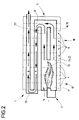
- FIG. 2 shows the principle of constitution of the improved boiler according to the invention.
- Said boiler is conventionally formed of a front facade element 1 on which is mounted a burner 2, for example with blown air, of a rear facade element 3 and of simple intermediate exchanger elements such as 4 or reinforced 5 , the assembly being assembled by nipples and horizontal tie rods.
- the exchanger elements 4 and 5 have upper flues such as 6, with pins or fins, arranged symmetrically in several horizontal stages.
- first group 7 along which the combustion gases and fumes are evacuated towards the front of the boiler, along a horizontal path going A, by a return compartment 8 of the rear facade, then evacuated towards the rear, along a horizontal return path B, along a second group 9 of several stages of flues by a collector 10 of the front facade.
- the exchanger elements 4 and 5 have in their second half-part a flame passage, respectively 11 and 12, entirely free for the first or occupied by additional exchange elements which will be discussed below for the second.
- the burner projects a flame 13 which develops along a combustion chamber 14. formed by the succession of flame passages 11 and 12 of the various simple and then reinforced intermediate exchangers delimiting a first part 15 and then a second part 16.
- the original characteristic of this boiler is located at the level of the reinforced intermediate elements 5, one of which is shown in detail in FIG. 1.
- These reinforced intermediate elements are constituted so that after assembly, the second part 16 of the chamber combustion 14 is equipped with additional exchange surfaces, formed by the presence of a group of additional water channels crossing the flame passage and communicating with the casing 17 of water circulation surrounding said combustion chamber.
- the external surfaces of the walls of the water arms 18 and 19 are conventionally provided with pins or fins 20 promoting heat exchange.
- the combustion chamber 14 After assembly of the boiler, the combustion chamber 14 consists of the first conventional part 15 in a fully open space and the second part 16 partially closed transversely by the succession of water arms 18 and 19 of the reinforced exchangers 5 juxtaposed.
- the hot gases and fumes return towards the front of the boiler along the flues A and are directed towards the outlet of the combustion gases and fumes in the upper part of the rear facade 3 by the upper flues B arranged on several horizontal stages.
Landscapes
- Engineering & Computer Science (AREA)
- Physics & Mathematics (AREA)
- Thermal Sciences (AREA)
- Chemical & Material Sciences (AREA)
- Combustion & Propulsion (AREA)
- Mechanical Engineering (AREA)
- General Engineering & Computer Science (AREA)
- Instantaneous Water Boilers, Portable Hot-Water Supply Apparatuses, And Control Of Portable Hot-Water Supply Apparatuses (AREA)
- Details Of Fluid Heaters (AREA)
Claims (10)
Applications Claiming Priority (2)
| Application Number | Priority Date | Filing Date | Title |
|---|---|---|---|
| FR9011591 | 1990-09-17 | ||
| FR9011591A FR2666873B1 (fr) | 1990-09-17 | 1990-09-17 | Chaudiere a elements intermediaires renforces. |
Publications (3)
| Publication Number | Publication Date |
|---|---|
| EP0477116A1 EP0477116A1 (de) | 1992-03-25 |
| EP0477116B1 true EP0477116B1 (de) | 1995-01-04 |
| EP0477116B2 EP0477116B2 (de) | 1999-10-27 |
Family
ID=9400474
Family Applications (1)
| Application Number | Title | Priority Date | Filing Date |
|---|---|---|---|
| EP19910440074 Expired - Lifetime EP0477116B2 (de) | 1990-09-17 | 1991-09-17 | Heizkessel mit verstärkten Zwischenelementen |
Country Status (3)
| Country | Link |
|---|---|
| EP (1) | EP0477116B2 (de) |
| DE (1) | DE69106466T3 (de) |
| FR (1) | FR2666873B1 (de) |
Family Cites Families (2)
| Publication number | Priority date | Publication date | Assignee | Title |
|---|---|---|---|---|
| DE404369C (de) * | 1921-10-30 | 1924-10-17 | Gustave Nordon | Heizungskessel mit Wassermantel und im Feuerraum liegenden Wasserrohrreihen |
| DE8901203U1 (de) * | 1988-02-06 | 1989-03-23 | Joh. Vaillant Gmbh U. Co, 5630 Remscheid | Gliederkessel |
-
1990
- 1990-09-17 FR FR9011591A patent/FR2666873B1/fr not_active Expired - Fee Related
-
1991
- 1991-09-17 EP EP19910440074 patent/EP0477116B2/de not_active Expired - Lifetime
- 1991-09-17 DE DE1991606466 patent/DE69106466T3/de not_active Expired - Fee Related
Also Published As
| Publication number | Publication date |
|---|---|
| FR2666873B1 (fr) | 1995-07-21 |
| DE69106466T2 (de) | 1995-06-22 |
| EP0477116A1 (de) | 1992-03-25 |
| DE69106466D1 (de) | 1995-02-16 |
| DE69106466T3 (de) | 2000-06-15 |
| FR2666873A1 (fr) | 1992-03-20 |
| EP0477116B2 (de) | 1999-10-27 |
Similar Documents
| Publication | Publication Date | Title |
|---|---|---|
| CA1118988A (fr) | Procede de fabrication d'un element d'echange indirect de chaleur en matiere ceramique | |
| CA3011196A1 (fr) | Echangeur de chaleur a condensation muni d'un dispositif d'echanges thermiques | |
| FR2757259A1 (fr) | Ailette metallique perfectionnee pour echangeur de chaleur, notamment pour vehicule automobile | |
| CN111829179B (zh) | 一种耦合预混水冷燃烧的单锅片串接铸铝硅热水炉 | |
| US4480591A (en) | Condensing boiler | |
| EP0477116B1 (de) | Heizkessel mit verstärkten Zwischenelementen | |
| FR2515803A1 (fr) | Echangeur de chaleur comportant un faisceau de tubes paralleles pouvant etre sollicite par de l'air, notamment pour la climatisation de l'habitacle d'un vehicule automobile | |
| EP0373027B1 (de) | Brennwertkessel für Heizung mit Wärmetransportflüssigkeit | |
| FR2553869A1 (fr) | Chaudiere a condensation pour chauffage a fluide caloporteur | |
| EP0102911A2 (de) | Einrichtung und Verfahren zur Wärmerekuperation für einen Feuerraum | |
| EP0913651B1 (de) | Wärmetauscherelement mit hohem Wirkungsgrad für einen Heizkörper in einem Gliederheizkessel | |
| FR2512190A3 (fr) | Element de chaudiere pourvu d'ailettes d'echange thermique a profil special | |
| FR2619205A1 (fr) | Echangeur de chaleur a impact de jet | |
| FR2659689A1 (fr) | Circuit de refroidissement interne d'une aube directrice de turbine. | |
| EP0908691A1 (de) | Kreuzstromwärmetauscher | |
| FR2640028A2 (fr) | Chaudiere a condensation pour chauffage a fluide caloporteur | |
| BE481561A (de) | ||
| EP0193433A1 (de) | Heizungsanlage für offene Kamine mit umgekehrtem Zug | |
| FR2542851A1 (fr) | Recuperateur de chaleur a double circuit | |
| FR2492060A1 (fr) | Recuperateur de chaleur a tubes triangulaires | |
| FR2515805A1 (fr) | Echangeur de chaleur a elements modulaires | |
| EP0443931A1 (de) | Wärmerekuperator für Kaminöfen | |
| FR2658590A2 (fr) | Dispositif de recuperation de chaleur pour cheminee a atre. | |
| FR2601116A1 (fr) | Echangeur pour foyer insert de cheminee | |
| BE897390A (fr) | Perfectionnements aux cheminees |
Legal Events
| Date | Code | Title | Description |
|---|---|---|---|
| PUAI | Public reference made under article 153(3) epc to a published international application that has entered the european phase |
Free format text: ORIGINAL CODE: 0009012 |
|
| AK | Designated contracting states |
Kind code of ref document: A1 Designated state(s): CH DE ES GB IT LI |
|
| 17P | Request for examination filed |
Effective date: 19920725 |
|
| 17Q | First examination report despatched |
Effective date: 19930715 |
|
| GRAA | (expected) grant |
Free format text: ORIGINAL CODE: 0009210 |
|
| AK | Designated contracting states |
Kind code of ref document: B1 Designated state(s): CH DE ES GB IT LI |
|
| PG25 | Lapsed in a contracting state [announced via postgrant information from national office to epo] |
Ref country code: GB Effective date: 19950104 Ref country code: ES Free format text: THE PATENT HAS BEEN ANNULLED BY A DECISION OF A NATIONAL AUTHORITY Effective date: 19950104 |
|
| REF | Corresponds to: |
Ref document number: 69106466 Country of ref document: DE Date of ref document: 19950216 |
|
| ITF | It: translation for a ep patent filed | ||
| GBV | Gb: ep patent (uk) treated as always having been void in accordance with gb section 77(7)/1977 [no translation filed] |
Effective date: 19950104 |
|
| PLBI | Opposition filed |
Free format text: ORIGINAL CODE: 0009260 |
|
| 26 | Opposition filed |
Opponent name: RAPIDO WAERMETECHNIK GMBH Effective date: 19950929 |
|
| PLBF | Reply of patent proprietor to notice(s) of opposition |
Free format text: ORIGINAL CODE: EPIDOS OBSO |
|
| PGFP | Annual fee paid to national office [announced via postgrant information from national office to epo] |
Ref country code: CH Payment date: 19960912 Year of fee payment: 6 |
|
| PG25 | Lapsed in a contracting state [announced via postgrant information from national office to epo] |
Ref country code: LI Free format text: LAPSE BECAUSE OF NON-PAYMENT OF DUE FEES Effective date: 19970930 Ref country code: CH Free format text: LAPSE BECAUSE OF NON-PAYMENT OF DUE FEES Effective date: 19970930 |
|
| REG | Reference to a national code |
Ref country code: CH Ref legal event code: PL |
|
| PLAW | Interlocutory decision in opposition |
Free format text: ORIGINAL CODE: EPIDOS IDOP |
|
| PLAW | Interlocutory decision in opposition |
Free format text: ORIGINAL CODE: EPIDOS IDOP |
|
| PUAH | Patent maintained in amended form |
Free format text: ORIGINAL CODE: 0009272 |
|
| STAA | Information on the status of an ep patent application or granted ep patent |
Free format text: STATUS: PATENT MAINTAINED AS AMENDED |
|
| 27A | Patent maintained in amended form |
Effective date: 19991027 |
|
| AK | Designated contracting states |
Kind code of ref document: B2 Designated state(s): CH DE ES GB IT LI |
|
| PG25 | Lapsed in a contracting state [announced via postgrant information from national office to epo] |
Ref country code: IT Free format text: LAPSE BECAUSE OF NON-PAYMENT OF DUE FEES;WARNING: LAPSES OF ITALIAN PATENTS WITH EFFECTIVE DATE BEFORE 2007 MAY HAVE OCCURRED AT ANY TIME BEFORE 2007. THE CORRECT EFFECTIVE DATE MAY BE DIFFERENT FROM THE ONE RECORDED. Effective date: 20050917 |
|
| PGFP | Annual fee paid to national office [announced via postgrant information from national office to epo] |
Ref country code: DE Payment date: 20060921 Year of fee payment: 16 |
|
| PG25 | Lapsed in a contracting state [announced via postgrant information from national office to epo] |
Ref country code: DE Free format text: LAPSE BECAUSE OF NON-PAYMENT OF DUE FEES Effective date: 20080401 |