EP0475572B1 - Dispositif de liaison à fibres optiques avec atténuateur - Google Patents
Dispositif de liaison à fibres optiques avec atténuateur Download PDFInfo
- Publication number
- EP0475572B1 EP0475572B1 EP91307136A EP91307136A EP0475572B1 EP 0475572 B1 EP0475572 B1 EP 0475572B1 EP 91307136 A EP91307136 A EP 91307136A EP 91307136 A EP91307136 A EP 91307136A EP 0475572 B1 EP0475572 B1 EP 0475572B1
- Authority
- EP
- European Patent Office
- Prior art keywords
- plug
- sleeve
- optical fiber
- cap
- connector
- Prior art date
- Legal status (The legal status is an assumption and is not a legal conclusion. Google has not performed a legal analysis and makes no representation as to the accuracy of the status listed.)
- Expired - Lifetime
Links
- 239000013307 optical fiber Substances 0.000 title claims description 48
- 230000008878 coupling Effects 0.000 claims description 25
- 238000010168 coupling process Methods 0.000 claims description 25
- 238000005859 coupling reaction Methods 0.000 claims description 25
- 239000000835 fiber Substances 0.000 claims description 24
- 230000003287 optical effect Effects 0.000 claims description 13
- 239000011521 glass Substances 0.000 claims description 11
- 230000000712 assembly Effects 0.000 claims description 10
- 238000000429 assembly Methods 0.000 claims description 10
- 239000000463 material Substances 0.000 claims description 6
- 230000006835 compression Effects 0.000 claims description 5
- 238000007906 compression Methods 0.000 claims description 5
- 238000003780 insertion Methods 0.000 description 18
- 230000037431 insertion Effects 0.000 description 18
- 230000005540 biological transmission Effects 0.000 description 13
- 238000013461 design Methods 0.000 description 5
- 239000004033 plastic Substances 0.000 description 5
- 229920003023 plastic Polymers 0.000 description 5
- MCMNRKCIXSYSNV-UHFFFAOYSA-N Zirconium dioxide Chemical compound O=[Zr]=O MCMNRKCIXSYSNV-UHFFFAOYSA-N 0.000 description 4
- 230000002411 adverse Effects 0.000 description 3
- 229920003229 poly(methyl methacrylate) Polymers 0.000 description 3
- 239000004926 polymethyl methacrylate Substances 0.000 description 3
- 239000004800 polyvinyl chloride Substances 0.000 description 3
- 238000005253 cladding Methods 0.000 description 2
- 239000011248 coating agent Substances 0.000 description 2
- 238000000576 coating method Methods 0.000 description 2
- 238000012937 correction Methods 0.000 description 2
- 238000007667 floating Methods 0.000 description 2
- 239000007769 metal material Substances 0.000 description 2
- 238000000034 method Methods 0.000 description 2
- 229920000915 polyvinyl chloride Polymers 0.000 description 2
- 125000006850 spacer group Chemical group 0.000 description 2
- 229920002799 BoPET Polymers 0.000 description 1
- OKTJSMMVPCPJKN-UHFFFAOYSA-N Carbon Chemical compound [C] OKTJSMMVPCPJKN-UHFFFAOYSA-N 0.000 description 1
- 239000005041 Mylar™ Substances 0.000 description 1
- NIXOWILDQLNWCW-UHFFFAOYSA-N acrylic acid group Chemical group C(C=C)(=O)O NIXOWILDQLNWCW-UHFFFAOYSA-N 0.000 description 1
- 238000013459 approach Methods 0.000 description 1
- 239000004760 aramid Substances 0.000 description 1
- 229920003235 aromatic polyamide Polymers 0.000 description 1
- 230000002238 attenuated effect Effects 0.000 description 1
- 238000005452 bending Methods 0.000 description 1
- 229910052799 carbon Inorganic materials 0.000 description 1
- 230000015556 catabolic process Effects 0.000 description 1
- 229910010293 ceramic material Inorganic materials 0.000 description 1
- 238000004891 communication Methods 0.000 description 1
- 230000003247 decreasing effect Effects 0.000 description 1
- 238000006731 degradation reaction Methods 0.000 description 1
- 230000001419 dependent effect Effects 0.000 description 1
- 230000009977 dual effect Effects 0.000 description 1
- 230000000694 effects Effects 0.000 description 1
- 239000002657 fibrous material Substances 0.000 description 1
- 238000009434 installation Methods 0.000 description 1
- 230000000670 limiting effect Effects 0.000 description 1
- 230000000717 retained effect Effects 0.000 description 1
- 238000000926 separation method Methods 0.000 description 1
- 238000012360 testing method Methods 0.000 description 1
Images


Classifications
-
- G—PHYSICS
- G02—OPTICS
- G02B—OPTICAL ELEMENTS, SYSTEMS OR APPARATUS
- G02B6/00—Light guides; Structural details of arrangements comprising light guides and other optical elements, e.g. couplings
- G02B6/24—Coupling light guides
- G02B6/36—Mechanical coupling means
- G02B6/38—Mechanical coupling means having fibre to fibre mating means
-
- G—PHYSICS
- G02—OPTICS
- G02B—OPTICAL ELEMENTS, SYSTEMS OR APPARATUS
- G02B6/00—Light guides; Structural details of arrangements comprising light guides and other optical elements, e.g. couplings
- G02B6/24—Coupling light guides
- G02B6/26—Optical coupling means
- G02B6/264—Optical coupling means with optical elements between opposed fibre ends which perform a function other than beam splitting
- G02B6/266—Optical coupling means with optical elements between opposed fibre ends which perform a function other than beam splitting the optical element being an attenuator
Definitions
- This invention relates to an optical fiber connecting device including an attenuator.
- Attenuators are needed in the transmission path to reduce the strength of an incoming signal to a required level.
- Many optical fiber communication systems require a method of decreasing optical power at a reducing station to avoid the saturation of receivers. Such a reduction in power may be accomplished by introducing into the system a device known as an attenuator which is designed to dissipate or to attenuate a controlled fraction of the input power while allowing the balance to continue through the system.
- Attenuators for biconic optical connectors are available commercially in various configurations. See U. S. Patent No. 4,900,124.
- Prior art fixed attenuators generally fall into four classes.
- a second class design is one which comprises an air gap in which attenuation is increased by increasing the gap.
- a high density, translucent, laminated element that varies in the thickness of a carbon layer thereof for different attenuation levels is mounted in a transverse slot.
- an alignment sleeve includes an attenuating element capable of transverse movement in the alignment sleeve. See for example, U.S.
- a fourth class of attenuator for use in a biconic arrangement includes an index matched spacer. None of these appear to be suitable for use with cylindrical ferrule, single mode to single mode connecting arrangements where low reflectance is important.
- a very much used ferrule connector for terminating and connecting two optical fibers is one which is referred to as an ST® connector, ST being a registered trademark of AT&T.
- ST® connector is disclosed, for example, in U.S. patent 4,934,785.
- An ST connector includes a cylindrical plug or ferrule, as it is often called, having a passageway therethrough for receiving an end portion of an optical fiber to be terminated.
- the plug which is received in a cap is spring-loaded.
- Attenuator Complicating matters for attenuating cylindrical ferrule connections is the recognition that there is no universally accepted ferrule connector. Also available is a connector referred to as the FC connector. Desirably, the sought after attenuator may be used for either connector. What is needed and what does not seem to be available is an attenuator which may be used in single mode to single mode ferrule type connecting arrangements, such as for example, ST connector to ST connector, ST connector to FC connector or FC connector to FC connector.
- the sought-after attenuator is required for high speed lightwave transmission systems with distributed feedback lasers, and amplitude modulated cable television transmission where unwanted reflections in the network can result in optical feedback into the laser causing laser instability and receiver noise. Also, the sought-after low reflection attenuator is needed to minimize systems degradations due to multiple path interference.
- the sought after in-line attenuator must be structured keeping in mind that the level of reflected power can be affected adversely by a mismatch in index of refraction in the transmission path, by the length of the gap between optical fiber ends, by laser linewidth, by frequency and by the distance between the two connections.
- a ferrule connector for connecting two optical fibers each having a core and a cladding includes provisions for attenuation which results in relatively low reflected power. Included are two plugs each of which may be cylindrically shaped with a passageway extending therethrough for receiving an end portion of an optical fiber to be connected by the plugs. Each end of a split sleeve is adapted to receive one of the plugs in a manner so that when the two plugs are seated fully in the sleeve with surfaces of the plugs engaging conformable surfaces of walls which define a sleeve cavity, ends of the plugs are adjacent to each other.
- An attenuating portion of the connector includes a plate-like element which is mounted in the sleeve between the ends of the plugs.
- the attenuating portion is suspended slideably in the sleeve with major parallel faces thereof being perpendicular to a longitudinal axis of the sleeve.
- the plate-like element has an index of refraction which is about equal to that of the cores of optical fibers to be connected. Further, the plate-like element is held in the sleeve and the conformable surfaces of the plugs and the sleeve are such that end faces of the plugs when seated in the sleeve are caused to be in engagement with the plate-like element.
- the plate-like element is supported in the sleeve in a manner so that the plate-like element is capable of movement in a direction parallel to the longitudinal axis of the sleeve. This allows the plate-like element to become repositioned in the sleeve as the plugs are seated in the sleeve.
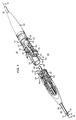
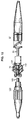
- FIGS. 1 and 2 there is shown a portion of an optical fiber connector arrangement 20 for providing an optical fiber connection between two optical fibers.
- the connector 20 is exemplary and others may include the arrangement of this invention.
- Each of two optical fibers 21-21 (see FIG. 3) to be connected includes a core 25 and a cladding 27, together designated 26, enclosed in a coating 28.
- the optical fiber may be enclosed in a tube of polyvinyl chloride (PVC) to provide what is referred to as a buffered fiber which may be terminated and connected in accordance with this invention.
- PVC polyvinyl chloride
- the connective arrangement of this invention also may be used to connect single fiber cables 30-30 (see again FIG. 1) in which covering a tube 31 of PVC is a strength member 33 such as one made of aramid fibrous material, for example, and an outer jacket 35 which may be comprised of PVC.
- the connector 20 comprises two optical fiber terminations or plug assemblies, each designated generally by the numeral 37. Corresponding elements of the terminations 37-37 are identified with the same numerals.
- the connector 20 is such that longitudinal axes 38-38 of the terminations are coaxial.
- each termination 37 comprises an optical fiber terminus or plug 40, having a passageway 41 (see FIG. 2) and being made of a glass, plastic or ceramic material.
- the plug 40 has an outer diameter of about 2.5 mm.
- An end face 39 of the plug 40 includes an opening of the passageway 41.
- the coating 28, as well as the tube 31, strength member 33 and outer jacket 35 is removed from an end portion of an optical fiber 21 prior to its termination with a plug 40. Then the uncoated end portion of the optical fiber is inserted into the passageway 41 of each plug 40. The uncoated end portion of the optical fiber 21 is secured within the passageway 41 of the plug 40 and the end faces of the optical fiber are cleaved and polished.
- Each termination also includes a connector body 42 or barrel (see FIGS. 1 and 2) made of a plastic or metallic material, a compression spring 44 and a tubular cap 45 made of a plastic or a metallic material. It should be observed that the plug 40, the connector body 42 and the cap 45 each has a cylindrical cross-section.
- the connector body 42 includes a separate orienting or alignment key 43 which projects radially from the longitudinal axis 38 and which can be installed at any one of a number of positions.
- the connector body 42 includes a small diameter portion 46 (see FIG. 2) which extends through an opening 47 in an internally disposed collar 48 in the cap 45.
- a retaining washer 49 circumscribes the small diameter portion on the outer side of the collar.
- the spring 44 is disposed about the smaller diameter portion 46 of the connector body 42 between the collar and a large diameter portion 51. As a result of this arrangement, the spring 44 biases the connector body 42 outwardly from the cable to hold the connector body within the cap 45.
- Each plug assembly also may be provided with means for limiting the allowable rotation of the cap 45 with respect to the connector body 42.
- the cap may include a stud (not shown) which projects inwardly from said annular collar 48 into a camming race provided in the connector body.
- the cap 45 includes a longitudinally extending slot 55 which at one end communicates with a circumferentially extending slot 57.
- the slot 57 is formed so that the tubular wall of the housing which defines it includes a latching projection 58.
- a portion 59 (see FIG. 1) which may extend from the cap 45 along the optical fiber cable in a conically shaped configuration.
- This portion of the connector 20 provides strain relief for the termination and ensures that the cable can withstand repeated bends in use after interconnection with another cable without undue stresses being imparted to the optical fibers.
- the connector arrangement also includes an attenuator arrangement which cooperates with a sleeve 60 (see FIGS 1 and 2) having a longitudinal slot 61.
- the sleeve is made of zirconia.
- the sleeve 60 is disposed within a housing 63 and maintained therein by a retainer 64 (see FIG. 2).
- the housing includes oppositely extending keyways 66-66 with each keyway 66 being associated with and adapted to receive a key 43. Further, associated with each keyway 66 at each end portion of the housing 63 are two diametrically opposed radially extending latching pins 67-67 each of which is displaced 90 ° from the associated keyway.
- each latching pin 67 enters and moves along a slot 57.
- each latching pin becomes disposed behind a latching projection 58.
- the plugs 40-40 disposed within the sleeve 60 should have their longitudinal axes aligned and end faces of the fibers with the end faces 39-39 of the plugs contacting an attenuator element 70 (see FIGS. 1 and 2).
- the outer surface of each plug 40 and the surfaces of the walls of the sleeve cavities are associated conformable alignment surfaces which are intended to cause desired positioning of the plugs when the end portions of the plugs are received in the sleeve 60.
- the plugs When disposed in the alignment sleeve 60, the plugs should have a desired end separation.
- the connector 20 includes an attenuator arrangement for adding attenuation and reducing return loss.
- the sleeve 60 includes the longitudinally extending slot 61 which performs a dual function. Not only does the slot 61 allow the sleeve to be compliant with different plug diameters within a tolerance range, but also it allows the attenuator element 70 to be moved longitudinally along the sleeve to be repositioned during insertion of the plugs 40-40.
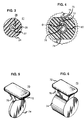
- the attenuator element 70 in side elevational view is T-shaped and includes a head 72 and a disc 74 which is engaged by each of the plugs 40-40 when the plugs are seated in the sleeve.
- the head 72 extends longitudinally along the slot 61 of the sleeve 60 and includes a neck 76 which is capable of being received in the sleeve slot.
- the head 72 and the neck 76 cooperate to form a rail-like configuration.
- the disc is plate-like and has a circular configuration in a plane normal to the longitudinal axis 38 of the connector.
- the head 72 is disposed within a channel 75 (see FIG. 2) which is formed in the housing 63.
- the ST connector is considered a floating design in which the two plugs are spring loaded and are aligned with a compliant split sleeve located in a coupling housing (FIG. 2).
- a first plug 40 When a first plug 40 is inserted into the coupling, the plug overtravels the transverse centerline of the coupling and its movement is arrested by the engagement of the plug connection body with a coupling shoulder.
- the second plug When the second plug is joined to the other side of the coupling and contact with the attenuator element is made by the two plugs, the first plug is pushed backwards until equilibrium is reached between the spring loading of the two plugs provided by the compression springs 44-44.
- the disc 74 is selected of a suitable thickness, flatness, surface finish, and parallelism to maintain fiber-end contract and to provide the desired attenuation.
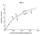
- the operative stem portion 74 of the attenuator has a thickness which ranges from about 200 to 1750 microns for a 5 dB to a 20 dB loss, respectively.
- PMMA polymethylmethacrylate
- the attenuator elements 70-70 are molded in various thicknesses to attain an attenuation range between 5 and 20 dB.
- the rail comprising the head and neck, allows the element to be moved by sliding along the slot in the ferrule sleeve, which is parallel to the fiber axis.
- the assembly which is shown in FIG. 4, has the neck riding in the slot of the split coupling sleeve.
- the rail and slot arrangement act to position and support the attenuator disc. Further, it provides freedom of longitudinal movement of the disc which is needed in the connection and disconnection of the plugs.
- the adjustable nature of the attenuator element 70 in the slot 61 is important.
- the hereinbefore described attenuator arrangement requires only that the ST connector coupling housing provide clearance for the attenuator support rail 72 to ride in the zirconia split sleeve 60.
- the width of the slot 61 in the sleeve 60 i.e. about 1.0 mm, has been increased over that of a prior art sleeve, i.e. about 0.5 mm, so as to allow the neck of the attenuator element 70 to extend therethrough.
- the attenuator element 70 is engaged by an end of the inserted plug to cause the attenuator to be moved slightly in the same direction as the direction of insertion, that is in a direction parallel to the longitudinal axis 38 of the connector. Then, when the other plug is inserted into the opposite end of the sleeve 60, the end of the other plug engages the attenuator element and causes it to be held securely between the two plugs.
- the floating support of the attenuator element is accomplished by the moveable element between fiber ends of two plugs with a material element having a thickness which is equal to a required value.
- the attenuator element has an index of refraction which is similar to that of the transmitting fiber core, i.e. glass.
- the plug travel allows for greater compression of the spring, resulting in additional space for a range of attenuator disc thicknesses. This allows the installation of attenuator elements having thicknesses on the order of 1.75 mm or less for a loss of 20 dB or less, while maintaining plug contact and float.
- IL single mode insertion loss
- Snell's law of refraction describes how light waves behave between materials with different indices of refraction, causing bending of light rays. Light accepted by a second fiber must impinge the core area and be within the critical angle of the fiber to be received.
- FIG. 7 shows plots designated 80 and 90 which depict the relationship between the theoretical insertion loss and attenuator element thickness at wavelengths of 1310 nm and 1550 nm.
- the plots are in accordance with equation (1).
- Each data point represents an average loss value for a group of attenuator elements 70-70 for the thickness corresponding to that data point. As thickness increases, insertion loss increases. What is desired is an attenuator element 70 that provides acceptable performance at both wavelengths.
- Figure 7 includes average data designated by points 92-92 at 1310 nm and 94-94 at 1550 nm from ST connectors of this invention. It should be noted that this arrangement for attenuation works equally well at 780 nm single mode to single mode transmission with a further wavelength dependent shift.
- connection arrangement of this invention which includes the attenuator element 70, results in substantially lower reflected power than in prior art arrangements.
- the index difference, n along an optical path causes reflection as stated by the following equation for return loss: where n 0 and n 1 are indices of refractions for two interfacing materials.
- both glass-to-air and air-to-glass interfaces contribute to the reflected power, which can be excessively high.
- the reflected loss is dominated by that interface between core glass and air which is first encountered in the direction of light transmission.
- the second interface that is from air-to-glass in the direction of transmission, has much less effect because of the attenuation caused by the transmission through the lengthened air gap.
- Another arrangement may include spaced fiber ends with an acrylic or Mylar plastic, in-line, plate-like attenuator element suspended in the air gap.
- this attenuator there are multiple reflected surfaces, even though, at best, the attenuator can contact only one fiber end with an air gap between the attenuator and the other fiber end.
- an attenuator material having an index n 0 which is close to that of glass high reflections can occur when relatively small air gaps exist. For low attenuation values, this gap is more critical. Reflected power in this arrangeinent, where the fiber contacts only one side of the optical disc, also is a function of the direction of optical transmission through the attenuator-air gap.
- the reflected power generally will be less if the direction of the transmission is through a contacting optical fiber-attenuator interface, through the attenuator and through the air gap to the second fiber end. If the direction of transmission is in the opposite direction, the reflected power can be similar to that across a relatively small air gap without an attenuator. In cases where a small gap exists on both sides of a plate-like low-value attenuator, i.e. 5 dB, poor return loss on the order of -6 dB has been measured.
- the attenuator arrangement of the connector 20 of this invention results in significantly less reflected power than in prior art cylindrical ferrule connection arrangements. This is accomplished by causing both plugs to engage the in-line attenuator element 70, thereby avoiding an air gap. It should be noted that the second plastic-to-optical fiber core glass interface, providing there is contact with the plug ends, is of less consequence because the low level of reflected power from the second interface would be attenuated by the two way loss of the attenuator.
- the total return loss from an arrangement in which there is a -40 dB loss from a first glass to attenuator interface and a -40 dB loss from the second interface between the attenuator and glass, on the outgoing side, and a 10 dB attenuator which contributes 20 dB for a round trip amounts to -39.96 dB. This is a negligible difference from that provided at the first interface.
- the connector 20 of this invention is compatible with existing connectors in the field. For example, if all new sleeves were to be provided with an attenuator, it becomes important that plugs already in use in the field be useable with such sleeves. As should be apparent, the use of a sleeve 60 with an attenuator in no way impedes its use with existing plugs.
- FIG. 8 depicts data points of return loss in -dB as a function of insertion loss in dB at 1310 nm for attenuator elements 70-70 of this invention.
- a relatively low return loss attenuator would be depicted by data points above the acceptable limit line in FIG. 8.
- the attenuator of this invention is a relatively low reflection design.
- the object of using an attenuator element of index matched material is to achieve a measured amount of insertion loss with a low reflectance. The thicker the element 70, the greater the loss. Because the attenuator element contacts the fiber ends, reflectance is minimized.
- FIG. 9 depicts histogram plots of frequency versus insertion loss in dB at 1310 nm. Allowable tolerance ranges are shown along the X axis. FIG. 9 shows that the results are reproducible. All samples in each insertion loss band have a relatively narrow distribution. Although the distribution is greater for insertion losses of 15 and 20 dB, they are still within the tolerance window.
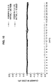
- FIG. 10 depicts the results of a humidity test for the attenuator of this invention at 90 to 95 % relative humidity at 60 ° C. As can be seen, the change in loss with time is negligible. This demonstrates that the attenuator is very stable with respect to time and humidity.
- a coupling 102 having center flange portions 104-104 includes two opposed entrances 106-106.
- Each entrance 106 includes an externally threaded portion 107 and a circular boss 108 having a flared entry portion 109.
- An outer diameter of each boss 108 is less than an inner diameter of the coupling 102 to provide an annular space 111 about each end.
- a sleeve 113 Disposed within the coupling 102 is a sleeve 113.
- the sleeve has a slot 115 formed longitudinally therealong, the slot having sufficient width to allow a neck portion of an attenuator element 70 to extend therethrough.
- the sleeve is retained within the coupling by engaging stepped inner portions of the bosses 108-108.
- a fiber to be connected to another by an FC arrangement is terminated by a plug assembly 120.
- Each plug assembly 120 includes a cylindrical plug or ferrule 122 which terminates a fiber.
- the plug 122 is received in a connector body or barrel 124 which is received in cap 126 that is threaded internally.
- the cap 126 is adapted to be turned threadably over the threaded portion 107 of the coupling 102 and to slide over the barrel 124.
- the barrel and plug are biased outwardly by a spring.
- a craftsperson When a connection is desired, a craftsperson causes the plug 122 of the plug assembly to become disposed in the sleeve 113 to contact an attenuator element 70 which is supported in the sleeve.
- the barrel 124 is moved slideably over the boss 108 while the cap 126 is turned threadably over an end portion 107 of the coupling.
- an appropriately sized spacer 114 is disposed between flange portions to compensate for the lack of sufficient travel of the FC plugs 122-122.
- ST connector to FC connector arrangement By this is meant that an ST connector ferrule is adapted to be connected optically through an attenuator arrangement with an FC connector ferrule.
- the capability demonstrates the versatility of the connector arrangement of this invention.
- FIG. 12 includes one portion, the right-hand portion as viewed in FIG. 12, which is similar to that of FIG. 2 and the other half similar to the arrangement of FIG. 11 with a match being made along a line disposed at about the halfway point of a sleeve 131 which is disposed in a housing 132. Inasmuch as portions of the ST connector portion and of the FC connector portion have been described hereinbefore, no further description of these portions is deemed necessary.
- insertion of either the plug of the FC connector portion or the plug of the ST connector portion causes the plug of either to engage the disc of the attenuator element 70 and causes the element, which is suspended by the rail, comprising the head and the neck, to be moved in a direction along the sleeve. Insertion of the other plug engages the other major surface of the disc and causes the disc to be moved in an opposite direction until the other plug assumes its connective position.
Landscapes
- Physics & Mathematics (AREA)
- General Physics & Mathematics (AREA)
- Optics & Photonics (AREA)
- Mechanical Coupling Of Light Guides (AREA)
- Light Guides In General And Applications Therefor (AREA)
- Optical Couplings Of Light Guides (AREA)
Claims (10)
- Système de liaison à fibres optiques, qui est adapté pour recevoir une atténuation avec une faible réflectance en direction du système, ledit système de liaison comprenant: une première fiche (40) qui termine une fibre optique (21), une deuxième fiche qui termine une autre fibre optique; un manchon (60) comportant une fente longitudinale (61) à travers sa paroi, le manchon étant adapté pour recevoir une des fiches dans chacune de ses extrémités; et un élément atténuateur (70) comprenant une partie en forme de plaque étant faite d'un matériau ayant un indice de réfraction substantiellement égal à celui du verre, ledit élément atténuateur étant capable d'être déplacé longitudinalement le long dudit manchon par chaque dite fiche lorsqu'elle est insérée dans ledit manchon pendant que ladite partie en forme de plaque est engagée par la face d'extrémité de chaque dite fiche lorsque lesdites fiches sont positionnées dans ledit manchon; ledit système de liaison étant caractérisé en ce que ledit élément atténuateur comprend un rail incluant une partie dépendante à partir de laquelle ladite partie en forme de plaque (74) est supportée, en conséquence de quoi ladite partie dépendante (76) s'étend le long et est adaptée de manière à être reçue par coulissement dans ladite fente avec ladite partie en forme de plaque étant positionnée à l'intérieur et en travers dudit manchon et avec une partie dudit rail (72) étant disposée en contiguïté avec une surface externe dudit manchon.
- Système de liaison à fibres optiques de la revendication 1, dans lequel ledit manchon (60) est positionné dans un logement (63) comportant des parties d'extrémités opposées, chaque partie d'extrémité incluant une partie externe qui est filetée extérieurement et un bossage de diamètre réduit qui est positionné concentriquement à l'intérieur et écarté de ladite partie externe et dans lequel ledit système inclut deux assemblages de fiches, chacun d'eux incluant une desdites première et deuxième fiches,
chaque dite fiche étant maintenue dans et s'étendant hors d'une partie de corps de connecteur (42) de l'assemblage, le corps de connecteur étant adapté pour venir se positionner autour dudit bossage d'une partie d'extrémité dudit logement quand ladite fiche est logée dans ledit manchon, de plus ledit assemblage de fiche incluant un couvercle à filetage interne qui peut être déplacé par coulissement par rapport à ladite partie de corps de connecteur de sorte que lorsque ladite fiche est logée dans ledit manchon et que ladite partie de corps de connecteur est positionnée autour dudit bossage, ledit couvercle est capable d'être déplacé par coulissement par rapport audit corps de connecteur pendant qu'il est vissé sur les filets de ladite partie externe dudit logement,
dans lequel ledit logement est dimensionné de manière à permettre aux deux dites fiches d'être positionnées dans ledit manchon malgré un degré limité de mouvement en arrière de chaque dite fiche quand lesdites fiches engagent ladite partie en forme de plaque. - Système de liaison à fibres optiques de la revendication 1, qui inclut deux assemblages de fiches dont chacun inclut une desdites première et deuxième fiches et dans lequel ledit manchon est positionné dans un logement (63) comportant des parties d'extrémités opposées, une première desdites parties d'extrémités incluant une partie externe qui est filetée extérieurement et un bossage de diamètre réduit qui est positionné concentriquement à l'intérieur et écarté de ladite partie externe et dans lequel la deuxième partie d'extrémité opposée inclut une partie tubulaire ayant une rainure de guidage s'y étendant longitudinalement et deux ergots d'enclenchement (67-67) diamétralement opposés faisant saillie par rapport à une de ses surfaces externes,
un premier desdits assemblages de fiches incluant ladite première fiche s'étendant hors d'un corps de connecteur (42) qui est adapté pour se positionner autour dudit bossage de ladite première partie d'extrémité dudit logement quand ladite première fiche se loge dans ledit manchon et incluant de plus un couvercle (45) qui peut être déplacé par coulissement et qui est fileté intérieurement pour être vissé sur la partie externe filetée de ladite première partie d'extrémité dudit logement quand ladite première fiche se loge dans ledit manchon; et
un deuxième desdits assemblages de fiches incluant un corps de connecteur hors duquel s'étend ladite deuxième fiche, ledit corps de connecteur dudit deuxième assemblage de fiche comportant un panneton y faisant saillie pour être logé dans ladite rainure de guidage dudit logement quand ladite deuxième fiche se loge dans ledit manchon, ledit deuxième desdits assemblages de fiches incluant aussi un couvercle qui est positionné concentriquement autour d'au moins une partie dudit corps de connecteur et qui inclut deux fentes à cames et des fentes d'enclenchement associées de sorte que lorsque ladite deuxième fiche est insérée dans ledit manchon et que ledit panneton se loge dans ladite rainure de guidage dudit logement, chacun desdits ergots dudit logement soit incité à être déplacé le long d'une fente à came et se positionne dans la fente d'enclenchement associée avec lui pour maintenir ledit couvercle dudit deuxième assemblage de fiche assemblé audit logement. - Système de liaison à fibres optiques de la revendication 3, dans lequel ledit deuxième assemblage de fiche inclut un ressort de compression positionné autour de son dit corps de connecteur et ledit premier assemblage de fiche inclut un moyen élastique pour pousser ladite première fiche vers l'extérieur dudit premier assemblage de fiche.
- Connecteur à fibres optiques (20) pour relier une fibre optique (21) d'un câble de fibres optiques (35) à un moyen optique, ledit connecteur comprenant un assemblage de fiche (37) qui inclut une extrémité d'entrée pour un câble de fibres optiques comprenant une fibre optique et une extrémité de liaison, une fiche (40) adaptée à la terminaison d'une fibre optique, un couvercle qui est assemblé sur ladite fiche, et un moyen élastique pour pousser ladite fiche vers l'extérieur dudit couvercle dans une direction s'éloignant de ladite extrémité d'entrée de la fibre optique, ledit assemblage de fiche adapté pour être relié au moyen optique à ladite extrémité de liaison, et un manchon (60) pour loger ladite fiche dudit assemblage de fiche dans une de ses extrémités et un moyen optique positionné dans l'autre extrémité dudit manchon pour inciter la fibre optique terminée par ladite fiche à s'accoupler optiquement au moyen optique, ledit manchon comportant une paroi dont la surface interne s'adapte à la configuration de la fiche devant y être logée avec ladite paroi comportant une fente formée longitudinalement à travers elle,
un élément atténuateur (70) qui est adapté pour pouvoir être déplacé longitudinalement par coulissement le long d'une longueur substantielle dudit manchon, ledit élément atténuateur incluant une partie en forme de plaque positionnée à l'intérieur et en travers dudit manchon, ledit élément en forme de plaque dans ledit manchon étant engagé et déplacé par la face d'extrémité de ladite fiche quand ladite fiche est insérée dans ledit manchon, ledit connecteur étant caractérisé par ledit élément en forme de plaque (74) étant supporté par un rail (72) qui inclut une partie en col (76) s'étendant le long de et supportée par coulissement dans ladite fente. - Connecteur à fibres optiques de la revendication 5, dans lequel l'assemblage de fiche inclut aussi un corps de connecteur (42) pour maintenir ladite fiche (40), ledit élément en forme de plaque inclut une partie en forme de disque (74) qui est supportée à l'intérieur dudit manchon et qui est reliée par une dite partie en col à une partie de support, ladite partie de support étant positionnée à l'extérieur de ladite fente et engageant une surface externe dudit manchon avec ladite partie en col s'étendant à travers ladite fente.
- Connecteur à fibres optiques (20) de la revendication 5, dans lequel le moyen optique est une autre fibre optique, ledit connecteur comprenant:
un premier et un deuxième assemblages de fiches (37-37) dont chacun inclut une fiche de forme cylindrique comportant un passage à travers elle et étant adaptée pour former la terminaison d'une fibre optique positionnée dans ledit passage et un couvercle (45) qui renferme une partie de ladite fiche, chacun desdits assemblages de fiches incluant un moyen pour inciter sa dite fiche à être poussée vers l'extérieur dans une direction allant d'une extrémité d'entrée de la fibre vers une extrémité opposée de celle-ci;
un moyen d'accouplement incluant un logement contenant ledit manchon pour loger les parties d'extrémités de la fiche de chacun desdits assemblages de fiches pour maintenir lesdites parties d'extrémités dans ledit manchon en alignement l'une avec l'autre, chaque dit couvercle étant adapté pour être fixé à une partie d'extrémité dudit logement dudit moyen d'accouplement, et ledit élément en forme de plaque dudit élément atténuateur à l'intérieur dudit manchon étant engagé par la face d'extrémité de chaque dite fiche quand elle est insérée dans ledit manchon. - Connecteur à fibres optiques de la revendication 7, dans lequel chacun desdits assemblages de fiches (37-37) inclut un couvercle comportant une lèvre annulaire intérieure faisant saillie vers l'intérieur à travers lequel s'étend un corps de connecteur dans lequel est positionnée une partie d'extrémité de ladite fiche, ledit corps de connecteur comportant une partie d'extrémité avant agrandie, hors de laquelle fait saillie une partie d'extrémité de ladite fiche, chaque dit assemblage de fiche incluant aussi une pince de retenue qui est positionnée autour d'une partie d'extrémité arrière dudit corps de connecteur en contiguïté avec un côté interne de ladite lèvre et un ressort de compression positionné autour dudit corps de connecteur de manière à appuyer contre un côté avant de ladite lèvre et un côté arrière de ladite partie agrandie dudit corps de connecteur pour pousser ainsi ledit corps de connecteur et sa fiche vers l'extérieur avec ladite pince de retenue maintenant ladite fiche dans ledit couvercle, ledit corps de connecteur incluant aussi un panneton qui y fait saillie radialement par rapport à sa dite partie agrandie.
- Connecteur à fibres optiques de la revendication 8, dans lequel ledit logement inclut aussi un ergot d'enclenchement (67), ledit ergot se logeant dans une fente à came aménagée dans ledit couvercle de sorte que lorsque ledit ergot est positionné en contiguïté avec une extrémité arrière de ladite fente, un mouvement relatif de rotation par inadvertance entre ledit logement d'accouplement et ledit couvercle est empêché.
- Connecteur à fibres optiques de la revendication 9, dans lequel chaque dit couvercle inclut deux fentes à cames (57-57) diamétralement opposées dont chacune s'étend depuis une extrémité avant dudit couvercle vers l'intérieur en spirale autour dudit couvercle, chacune desdites fentes à cames communiquant avec une fente d'enclenchement associée qui s'étend depuis une extrémité arrière de la fente à came associées, vers l'avant selon une direction parallèle à un axe longitudinal de ladite fiche, chaque dit couvercle étant aussi pourvu d'entrées diamétralement opposées, chaque dite entrée à une extrémité d'accouplement dudit couvercle communiquant avec une extrémité avant d'une fente à came associée, ledit logement d'accouplement incluant une rainure de guidage, s'étendant longitudinalement, qui s'étend depuis une extrémité d'entrée dudit logement et une paire d'ergots d'enclenchement diamétralement opposés faisant saillie vers l'extérieur rapport audit logement, lesdits ergote et ladite rainure de guidage étant tels que lorsqu'un couvercle d'un assemblage de fiche est aligné avec ledit moyen d'accouplement de sorte que le panneton de ladite fiche soit aligné avec une rainure de guidage dans une extrémité dudit logement, lesdits ergots du logement d'accouplement sont alignés avec lesdites fentes à cames dudit couvercle et adaptés pour être déplacés le long desdites entrées dans lesdites fentes à cames et dans lesdites fentes d'enclenchement pour permettre audit assemblage de fiche d'être fixé audit moyen d'accouplement.
Applications Claiming Priority (2)
| Application Number | Priority Date | Filing Date | Title |
|---|---|---|---|
| US07/566,588 US5082345A (en) | 1990-08-13 | 1990-08-13 | Optical fiber connecting device including attenuator |
| US566588 | 2000-05-08 |
Publications (2)
| Publication Number | Publication Date |
|---|---|
| EP0475572A1 EP0475572A1 (fr) | 1992-03-18 |
| EP0475572B1 true EP0475572B1 (fr) | 1995-10-18 |
Family
ID=24263517
Family Applications (1)
| Application Number | Title | Priority Date | Filing Date |
|---|---|---|---|
| EP91307136A Expired - Lifetime EP0475572B1 (fr) | 1990-08-13 | 1991-08-02 | Dispositif de liaison à fibres optiques avec atténuateur |
Country Status (13)
| Country | Link |
|---|---|
| US (1) | US5082345A (fr) |
| EP (1) | EP0475572B1 (fr) |
| JP (1) | JPH0812298B2 (fr) |
| KR (1) | KR100233766B1 (fr) |
| CN (1) | CN1024949C (fr) |
| AU (1) | AU632703B2 (fr) |
| CA (1) | CA2047374C (fr) |
| DE (1) | DE69113940T2 (fr) |
| DK (1) | DK0475572T3 (fr) |
| ES (1) | ES2078449T3 (fr) |
| HK (1) | HK88596A (fr) |
| MX (1) | MX174461B (fr) |
| TW (1) | TW240295B (fr) |
Families Citing this family (53)
| Publication number | Priority date | Publication date | Assignee | Title |
|---|---|---|---|---|
| JP2529468Y2 (ja) * | 1990-06-22 | 1997-03-19 | 株式会社ユニシアジェックス | アンチスキッドブレーキ装置 |
| JPH04238307A (ja) * | 1991-01-23 | 1992-08-26 | Nec Corp | 光デバイス端末 |
| US5136681A (en) * | 1991-07-09 | 1992-08-04 | Seikoh Giken Co., Ltd. | Optical powder attenuator of variable attenuation type |
| US5214732A (en) * | 1992-01-02 | 1993-05-25 | Adc Telecommunications, Inc. | Optical fiber retention mechanism for securing optical fiber cable |
| US5261019A (en) * | 1992-01-02 | 1993-11-09 | Adc Telecommunications, Inc. | Fiber optic connector |
| US5243681A (en) * | 1992-04-13 | 1993-09-07 | Amp Incorporated | Aperture disk attenuator for laser diode connector |
| US5263106A (en) * | 1992-06-16 | 1993-11-16 | Siecor Corporation | Fiber optic attenuator for use with ferrules |
| US5274729A (en) * | 1992-07-30 | 1993-12-28 | At&T Bell Laboratories | Universal optical fiber buildout system |
| DE4307986A1 (de) * | 1993-03-13 | 1994-09-15 | Hirschmann Richard Gmbh Co | Optische Sendevorrichtung |
| US5870514A (en) * | 1993-05-14 | 1999-02-09 | National Research Council Of Canada | Optical in-line elements in fiber optic systems |
| US5396572A (en) * | 1993-08-10 | 1995-03-07 | At&T Corp. | Optical fiber connector having a unipartite cap |
| US5408557A (en) * | 1994-04-20 | 1995-04-18 | Hsu; Chung-Tang | FC-type optical fiber cable connector's adaptor |
| US5631989A (en) * | 1995-11-22 | 1997-05-20 | Lucent Technologies Inc. | Fiber and active optical device interconnection assembly |
| US5619610A (en) * | 1995-12-29 | 1997-04-08 | Lucent Technologies Inc. | Optical terminator |
| US5701382A (en) * | 1996-07-05 | 1997-12-23 | Molex Incorporated | Fiber optic attenuator |
| US5751874A (en) * | 1996-09-13 | 1998-05-12 | Nuvisions International, Inc. | Coupling device for linking optical fiber connectors |
| US5818992A (en) * | 1997-03-03 | 1998-10-06 | Lucent Technologies Inc. | Thermo-plastic optical terminator having a glass-transition temperature greater than 80° C. |
| US6367986B1 (en) * | 1997-12-12 | 2002-04-09 | Takeo Inagaki | Dispenser and optical fiber connector |
| SE510983C2 (sv) * | 1997-12-23 | 1999-07-19 | Ericsson Telefon Ab L M | Kontaktdon för optofiber |
| US6097873A (en) * | 1998-01-14 | 2000-08-01 | Lucent Technologies Inc. | Optical fiber attenuator device using an elastomeric attenuator member |
| US6104856A (en) * | 1998-06-16 | 2000-08-15 | Lucent Technologies Inc. | Optical air-gap attenuator |
| US6102581A (en) * | 1998-06-16 | 2000-08-15 | Lucent Technologies Inc. | Optical adapter including a ferrule assembly |
| US6149315A (en) * | 1998-09-04 | 2000-11-21 | Lucent Technologies Inc. | Side load resistant buildout |
| US6188827B1 (en) * | 1998-09-04 | 2001-02-13 | Lucent Technologies Inc. | Attenuator element for a buildout system |
| US6196729B1 (en) * | 1998-09-04 | 2001-03-06 | Lucent Technologies Inc. | Apparatus for retaining an attenuator element |
| US6151438A (en) * | 1998-09-24 | 2000-11-21 | Lucent Technologies Inc. | Fiber device having variable refractive index region proximal the core |
| JP3825930B2 (ja) * | 1999-01-28 | 2006-09-27 | ヒロセ電機株式会社 | 光コネクタ |
| US6357933B1 (en) | 1999-03-30 | 2002-03-19 | Lucent Technologies Inc. | Quick connect optical fiber ferrule connector |
| US6447172B1 (en) | 1999-04-01 | 2002-09-10 | Fitel Usa Corp. | Sleeve holder for optical fiber buildout |
| US6283640B1 (en) | 1999-04-01 | 2001-09-04 | Lucent Technologies Inc. | Tunable optical fiber buildout |
| US6524014B2 (en) * | 1999-04-01 | 2003-02-25 | Fitel Usa Corp. | Universal modular optical fiber buildout |
| US6188825B1 (en) | 1999-04-15 | 2001-02-13 | Lucent Technologies, Inc. | Dust cover for protecting optical fiber sleeve housing |
| JP3654063B2 (ja) * | 1999-07-12 | 2005-06-02 | ソニー株式会社 | 光コネクタ |
| US6253017B1 (en) * | 1999-08-04 | 2001-06-26 | Delphi Technologies, Inc. | Fiber optic connector with optical attenuator |
| US6367984B1 (en) | 1999-11-10 | 2002-04-09 | Lucent Technologies, Inc. | Optical fiber adapter |
| US6275643B1 (en) | 2000-02-09 | 2001-08-14 | Lucent Technologies, Inc. | Attenuator element for use with an optical fiber adapter |
| US6501900B1 (en) | 2000-02-17 | 2002-12-31 | Fitel Usa Corp. | Variable optical fiber attenuator device |
| AU2001280506A1 (en) * | 2000-07-19 | 2002-02-05 | The Johns Hopkins University | Fiber optic coupler with in-line optical component |
| US6695485B1 (en) * | 2000-07-28 | 2004-02-24 | Tellabs Operations, Inc. | Bezel for fiber optic components |
| US6623174B2 (en) | 2000-10-12 | 2003-09-23 | Tyco Electronics Corporation | Optical connector |
| US6461055B1 (en) | 2001-04-11 | 2002-10-08 | Adc Telecommunications, Inc. | Fiber optic adapter with attenuator and method |
| US6494706B2 (en) | 2001-04-18 | 2002-12-17 | L. L. Culmat, Lp | Optical attenuator mold |
| US6609837B2 (en) | 2001-04-27 | 2003-08-26 | Fitel Usa Corp. | Optical fiber adapter for dissimilar size ferrules |
| US6869316B2 (en) * | 2002-06-27 | 2005-03-22 | Dell Products L.P. | Three contact barrel power connector assembly |
| US20040091228A1 (en) * | 2002-11-09 | 2004-05-13 | Fitel Usa Corp. | High performance fiber optic attenuator and attenuating element |
| US7031589B2 (en) * | 2002-11-09 | 2006-04-18 | Furukawa Electric North America | Material for attenuating light signals with low reflectance in a fiber optic network |
| DE202005005362U1 (de) | 2005-04-05 | 2005-06-02 | Rosenberger Hochfrequenztechnik Gmbh & Co. Kg | Datenübertragungskabel mit FAKRA-Gehäuse |
| US20080089650A1 (en) * | 2006-05-24 | 2008-04-17 | Fiber Systems International D/B/A Amphenol Fiber Systems International | Fiber optic connector |
| CN101188179B (zh) | 2006-11-15 | 2010-05-26 | 清华大学 | 场发射电子源的制造方法 |
| TWM425286U (en) * | 2011-09-26 | 2012-03-21 | Gloriole Electroptic Technology Corp | Fiber optic attenuator |
| JP2015125217A (ja) * | 2013-12-26 | 2015-07-06 | 住友電気工業株式会社 | 光結合機構及び光トランシーバ |
| CN104932062A (zh) * | 2015-06-29 | 2015-09-23 | 周其 | 一种光纤连接器夹持装置 |
| US20230417999A1 (en) * | 2022-06-24 | 2023-12-28 | Acon Optics Communications Inc. | Optical-fiber connector with a protective cap and standard connector |
Family Cites Families (8)
| Publication number | Priority date | Publication date | Assignee | Title |
|---|---|---|---|---|
| GB2138161B (en) * | 1983-04-15 | 1986-05-08 | Standard Telephones Cables Ltd | Attenuator in optical fibre connector |
| US4934785A (en) * | 1983-08-29 | 1990-06-19 | American Telephone And Telegraph Company | Optical fiber connector |
| US4812006A (en) * | 1983-11-23 | 1989-03-14 | Amphenol Corporation | Fiber optic connector with colley retention |
| US4717234A (en) * | 1986-03-20 | 1988-01-05 | Gte Products Corporation | In-line optical attenuators |
| US4880291A (en) * | 1988-02-04 | 1989-11-14 | American Telephone & Telegraph Company, At&T Bell Laboratories | Optical fiber connector and methods of making |
| DE8813714U1 (de) * | 1988-06-11 | 1988-12-22 | Krone AG, 1000 Berlin | Optisches Dämpfungsglied |
| US4898446A (en) * | 1988-10-28 | 1990-02-06 | American Telephone And Telegraph Company, At&T Bell Laboratories | Optical fiber connector |
| US4900124A (en) * | 1988-12-12 | 1990-02-13 | American Telephone & Telegraph Company, At&T Bell Laboratories | Biconic optical fiber connecting device having attenuator |
-
1990
- 1990-08-13 US US07/566,588 patent/US5082345A/en not_active Expired - Lifetime
-
1991
- 1991-07-18 CA CA002047374A patent/CA2047374C/fr not_active Expired - Fee Related
- 1991-07-30 AU AU81509/91A patent/AU632703B2/en not_active Ceased
- 1991-08-02 DE DE69113940T patent/DE69113940T2/de not_active Expired - Lifetime
- 1991-08-02 TW TW080106077A patent/TW240295B/zh active
- 1991-08-02 ES ES91307136T patent/ES2078449T3/es not_active Expired - Lifetime
- 1991-08-02 DK DK91307136.1T patent/DK0475572T3/da active
- 1991-08-02 EP EP91307136A patent/EP0475572B1/fr not_active Expired - Lifetime
- 1991-08-09 MX MX9100604A patent/MX174461B/es not_active IP Right Cessation
- 1991-08-12 CN CN91105541A patent/CN1024949C/zh not_active Expired - Fee Related
- 1991-08-12 KR KR1019910013851A patent/KR100233766B1/ko not_active IP Right Cessation
- 1991-08-13 JP JP3226329A patent/JPH0812298B2/ja not_active Expired - Lifetime
-
1996
- 1996-05-23 HK HK88596A patent/HK88596A/xx not_active IP Right Cessation
Also Published As
| Publication number | Publication date |
|---|---|
| MX174461B (es) | 1994-05-17 |
| AU632703B2 (en) | 1993-01-07 |
| KR100233766B1 (ko) | 1999-12-01 |
| JPH04254804A (ja) | 1992-09-10 |
| US5082345A (en) | 1992-01-21 |
| CA2047374A1 (fr) | 1992-02-14 |
| DE69113940D1 (de) | 1995-11-23 |
| EP0475572A1 (fr) | 1992-03-18 |
| JPH0812298B2 (ja) | 1996-02-07 |
| ES2078449T3 (es) | 1995-12-16 |
| DE69113940T2 (de) | 1996-04-11 |
| DK0475572T3 (da) | 1995-11-27 |
| CA2047374C (fr) | 1994-06-14 |
| TW240295B (fr) | 1995-02-11 |
| AU8150991A (en) | 1992-02-20 |
| KR920004871A (ko) | 1992-03-28 |
| HK88596A (en) | 1996-05-31 |
| CN1062215A (zh) | 1992-06-24 |
| CN1024949C (zh) | 1994-06-08 |
Similar Documents
| Publication | Publication Date | Title |
|---|---|---|
| EP0475572B1 (fr) | Dispositif de liaison à fibres optiques avec atténuateur | |
| EP0373825B1 (fr) | Elément de liaison biconique à fibre optique muni d'un atténuateur | |
| CA2050355C (fr) | Systeme a blocs de connexion de fibres optiques | |
| US6102581A (en) | Optical adapter including a ferrule assembly | |
| US7270487B2 (en) | Field installable optical fiber connector | |
| US5923805A (en) | Connector for plastic optical fiber | |
| US4934785A (en) | Optical fiber connector | |
| US5274729A (en) | Universal optical fiber buildout system | |
| CA1068952A (fr) | Connecteur pour monofibre optique | |
| US6669375B1 (en) | Multi-fiber, in-line attenuator module and assembly for optoelectronic networks | |
| US6104856A (en) | Optical air-gap attenuator | |
| EP1130431A2 (fr) | Atténuateur pour utiliser avec un adaptateur à fibre optique | |
| WO2017011258A1 (fr) | Fibre optique comprenant un réseau de bragg et revêtement en film mince et connecteur | |
| US20200174199A1 (en) | Fiber optic adatper with dust shutter assembly for receiving a fiber optic connector | |
| US10330868B2 (en) | Pluggable fiber loopback apparatus and methods for fiber optical systems | |
| EP0352900A1 (fr) | Commutateur de dérivation optique | |
| US5754721A (en) | Fiberoptic connector | |
| US20200386951A1 (en) | Dual ferrule optical connector signal testing converter and method of use | |
| US5870514A (en) | Optical in-line elements in fiber optic systems | |
| CN114868056A (zh) | 光学连接器组件 | |
| Hawk et al. | Low loss splicing and connection of optical waveguide cables | |
| CN114746786A (zh) | 光学连接器组件 | |
| Drake | A critical review of fiber optic connectors | |
| Ajemian | Transmission Techniques: Fiber Optics | |
| EP1380866A1 (fr) | Dispositif de couplage avec fibre optique |
Legal Events
| Date | Code | Title | Description |
|---|---|---|---|
| PUAI | Public reference made under article 153(3) epc to a published international application that has entered the european phase |
Free format text: ORIGINAL CODE: 0009012 |
|
| AK | Designated contracting states |
Kind code of ref document: A1 Designated state(s): DE DK ES FR GB IT SE |
|
| 17P | Request for examination filed |
Effective date: 19920904 |
|
| 17Q | First examination report despatched |
Effective date: 19940315 |
|
| RAP3 | Party data changed (applicant data changed or rights of an application transferred) |
Owner name: AT&T CORP. |
|
| GRAA | (expected) grant |
Free format text: ORIGINAL CODE: 0009210 |
|
| AK | Designated contracting states |
Kind code of ref document: B1 Designated state(s): DE DK ES FR GB IT SE |
|
| ITF | It: translation for a ep patent filed | ||
| ET | Fr: translation filed | ||
| REF | Corresponds to: |
Ref document number: 69113940 Country of ref document: DE Date of ref document: 19951123 |
|
| REG | Reference to a national code |
Ref country code: DK Ref legal event code: T3 |
|
| REG | Reference to a national code |
Ref country code: ES Ref legal event code: FG2A Ref document number: 2078449 Country of ref document: ES Kind code of ref document: T3 |
|
| PLBE | No opposition filed within time limit |
Free format text: ORIGINAL CODE: 0009261 |
|
| STAA | Information on the status of an ep patent application or granted ep patent |
Free format text: STATUS: NO OPPOSITION FILED WITHIN TIME LIMIT |
|
| 26N | No opposition filed | ||
| PGFP | Annual fee paid to national office [announced via postgrant information from national office to epo] |
Ref country code: DK Payment date: 20010618 Year of fee payment: 11 |
|
| PGFP | Annual fee paid to national office [announced via postgrant information from national office to epo] |
Ref country code: SE Payment date: 20010621 Year of fee payment: 11 |
|
| PGFP | Annual fee paid to national office [announced via postgrant information from national office to epo] |
Ref country code: ES Payment date: 20010803 Year of fee payment: 11 |
|
| REG | Reference to a national code |
Ref country code: GB Ref legal event code: IF02 |
|
| PG25 | Lapsed in a contracting state [announced via postgrant information from national office to epo] |
Ref country code: SE Free format text: LAPSE BECAUSE OF NON-PAYMENT OF DUE FEES Effective date: 20020803 Ref country code: ES Free format text: LAPSE BECAUSE OF NON-PAYMENT OF DUE FEES Effective date: 20020803 |
|
| PG25 | Lapsed in a contracting state [announced via postgrant information from national office to epo] |
Ref country code: DK Free format text: LAPSE BECAUSE OF NON-PAYMENT OF DUE FEES Effective date: 20020930 |
|
| REG | Reference to a national code |
Ref country code: DK Ref legal event code: EBP |
|
| EUG | Se: european patent has lapsed | ||
| REG | Reference to a national code |
Ref country code: ES Ref legal event code: FD2A Effective date: 20030912 |
|
| PG25 | Lapsed in a contracting state [announced via postgrant information from national office to epo] |
Ref country code: IT Free format text: LAPSE BECAUSE OF NON-PAYMENT OF DUE FEES;WARNING: LAPSES OF ITALIAN PATENTS WITH EFFECTIVE DATE BEFORE 2007 MAY HAVE OCCURRED AT ANY TIME BEFORE 2007. THE CORRECT EFFECTIVE DATE MAY BE DIFFERENT FROM THE ONE RECORDED. Effective date: 20050802 |
|
| PGFP | Annual fee paid to national office [announced via postgrant information from national office to epo] |
Ref country code: FR Payment date: 20090817 Year of fee payment: 19 |
|
| PGFP | Annual fee paid to national office [announced via postgrant information from national office to epo] |
Ref country code: GB Payment date: 20090825 Year of fee payment: 19 |
|
| PGFP | Annual fee paid to national office [announced via postgrant information from national office to epo] |
Ref country code: DE Payment date: 20090827 Year of fee payment: 19 |
|
| GBPC | Gb: european patent ceased through non-payment of renewal fee |
Effective date: 20100802 |
|
| REG | Reference to a national code |
Ref country code: FR Ref legal event code: ST Effective date: 20110502 |
|
| REG | Reference to a national code |
Ref country code: DE Ref legal event code: R119 Ref document number: 69113940 Country of ref document: DE Effective date: 20110301 |
|
| PG25 | Lapsed in a contracting state [announced via postgrant information from national office to epo] |
Ref country code: FR Free format text: LAPSE BECAUSE OF NON-PAYMENT OF DUE FEES Effective date: 20100831 Ref country code: DE Free format text: LAPSE BECAUSE OF NON-PAYMENT OF DUE FEES Effective date: 20110301 |
|
| PG25 | Lapsed in a contracting state [announced via postgrant information from national office to epo] |
Ref country code: GB Free format text: LAPSE BECAUSE OF NON-PAYMENT OF DUE FEES Effective date: 20100802 |