EP0472916B1 - Overhead door closer - Google Patents
Overhead door closer Download PDFInfo
- Publication number
- EP0472916B1 EP0472916B1 EP19910112549 EP91112549A EP0472916B1 EP 0472916 B1 EP0472916 B1 EP 0472916B1 EP 19910112549 EP19910112549 EP 19910112549 EP 91112549 A EP91112549 A EP 91112549A EP 0472916 B1 EP0472916 B1 EP 0472916B1
- Authority
- EP
- European Patent Office
- Prior art keywords
- slide rail
- door closer
- slider
- rod
- rotation
- Prior art date
- Legal status (The legal status is an assumption and is not a legal conclusion. Google has not performed a legal analysis and makes no representation as to the accuracy of the status listed.)
- Expired - Lifetime
Links
- 230000000903 blocking effect Effects 0.000 claims description 17
- 238000006073 displacement reaction Methods 0.000 claims description 7
- 230000007704 transition Effects 0.000 claims description 6
- 229920003023 plastic Polymers 0.000 claims description 4
- 239000004033 plastic Substances 0.000 claims description 4
- 230000008878 coupling Effects 0.000 claims 2
- 238000010168 coupling process Methods 0.000 claims 2
- 238000005859 coupling reaction Methods 0.000 claims 2
- 239000000463 material Substances 0.000 claims 2
- 230000000694 effects Effects 0.000 description 2
- 239000002655 kraft paper Substances 0.000 description 1
Images
Classifications
-
- E—FIXED CONSTRUCTIONS
- E05—LOCKS; KEYS; WINDOW OR DOOR FITTINGS; SAFES
- E05C—BOLTS OR FASTENING DEVICES FOR WINGS, SPECIALLY FOR DOORS OR WINDOWS
- E05C17/00—Devices for holding wings open; Devices for limiting opening of wings or for holding wings open by a movable member extending between frame and wing; Braking devices, stops or buffers, combined therewith
- E05C17/02—Devices for holding wings open; Devices for limiting opening of wings or for holding wings open by a movable member extending between frame and wing; Braking devices, stops or buffers, combined therewith by mechanical means
- E05C17/04—Devices for holding wings open; Devices for limiting opening of wings or for holding wings open by a movable member extending between frame and wing; Braking devices, stops or buffers, combined therewith by mechanical means with a movable bar or equivalent member extending between frame and wing
- E05C17/12—Devices for holding wings open; Devices for limiting opening of wings or for holding wings open by a movable member extending between frame and wing; Braking devices, stops or buffers, combined therewith by mechanical means with a movable bar or equivalent member extending between frame and wing consisting of a single rod
- E05C17/24—Devices for holding wings open; Devices for limiting opening of wings or for holding wings open by a movable member extending between frame and wing; Braking devices, stops or buffers, combined therewith by mechanical means with a movable bar or equivalent member extending between frame and wing consisting of a single rod pivoted at one end, and with the other end running along a guide member
- E05C17/28—Devices for holding wings open; Devices for limiting opening of wings or for holding wings open by a movable member extending between frame and wing; Braking devices, stops or buffers, combined therewith by mechanical means with a movable bar or equivalent member extending between frame and wing consisting of a single rod pivoted at one end, and with the other end running along a guide member with braking, clamping or securing means at the connection to the guide member
Definitions
- the invention relates to an overhead door closer in which a door closer arm is guided in a slide rail on the door frame side by means of a slide piece articulated to the door closer arm and a mechanical device which can be set up is provided for limiting the guide region of the slide rail for the slide piece in the slide rail.
- Such a door closer is known from the company publication "GEZE door closer", printed note 9.89. It is an overhead gear door closer with a slide rail with the designation T 5000.
- the opening angle at which the open door can be locked can be adjusted continuously between 80 ° and 130 ° via a mechanical lock.
- a locking device for door leaves with a door closer is known, the closer shaft of which is coupled to one end of an actuating arm, the other end engages via a slide in a guide rail which is assigned a holding unit which defines the slide in a certain open position.
- the holding unit has a locking knob which is loaded by a spring element in the locking direction and engages on the sliding piece.
- Such a locking device extends essentially transversely to the direction of displacement of the slider and can not be accommodated in the known guide rails because of the size. Such a locking device can be pushed over to completely open a door.
- the invention has for its object to provide a simple mechanical locking device for an overhead door closer of the type mentioned, which can be put in place from the outside and re-established.
- the locking devices are arranged in this door closer according to the invention in the slider and therefore do not take up any additional volume. It exists the possibility of overriding these locking devices, which fix the associated doors at a certain opening angle, so that the doors can be fully opened, for example. In a simple manner, it is also possible to switch on the locking devices again.
- a preferred embodiment of the door closer is specified in claim 3.
- the non-round rod is rotated by moving the associated sliding sleeve when the twisted transition piece is passed over. Due to the changing outer diameter, the respective blocking element is therefore displaced in the transverse direction of the slide rail and, together with a locking element on the rail side or directly with a slide rail wall, forms the mechanical locking device.
- the locking device can be set up in the longitudinal direction of the slide rail according to claim 8 by moving the locking element or by an adjustable attachment on the rotatable rod according to claim 9.
- the locking device can also be designed according to claims 12 and 13 according to the principle of a slip clutch in order to avoid overloading the door closer or its correspondingly loaded parts in the event of an overload on the door closer arm.
- FIGS. 1-6 the door closer arm 2, which is articulated to the gearbox accommodated in the housing and which is guided with its end in the slide rail 3 to be fastened on the door frame side, can be seen.
- the corresponding end of the door closer arm 2 is connected in an articulated manner to a slide piece 4, which is guided in the slide rail 3, which is C-shaped in cross section and open at the bottom.
- a rod 5 with a square cross section is guided with little play and is rotatably supported at its ends in the end plugs 32 and 33 of the slide rail 3.
- the diameter of the bore 41 corresponds approximately to the diagonal of the cross section of the rod 5.
- this rod 5 has a transition piece 51 twisted by 45 °.
- a sliding sleeve 6 is positively placed on the rod 5 with a corresponding bore and can be moved in the axial direction from the outside via the grip element 61. If this sliding sleeve 6 passes over the transition piece 51, the rod 5 is rotated in each case by 45 °.
- a locking device described below is actuated by this displacement of the sliding sleeve 6 or the resulting rotation of the rod 5.
- a chamber 42 is provided, which is open towards the top of the slide rail wall 31 and in which a plate-like blocking element 8, preferably made of plastic, is accommodated in a form-fitting manner but radially to the axis of rotation of the non-circular rod 5.
- This blocking element 8 rests on the non-circular rod 5, which is preferably square in cross section.
- a locking element 7 projecting slightly into the slide rail 3 is provided in a slot 311 which can be displaced in the longitudinal direction of the slide rail.
Landscapes
- Engineering & Computer Science (AREA)
- Mechanical Engineering (AREA)
- Power-Operated Mechanisms For Wings (AREA)
- Closing And Opening Devices For Wings, And Checks For Wings (AREA)
Description
Die Erfindung betrifft einen obenliegenden Türschließer, bei dem ein Türschließerarm mit Hilfe eines mit dem Türschließerarm gelenkig verbundenen Gleitstückes in einer türzargenseitigen Gleitschiene geführt und zur Begrenzung des Führungsbereiches der Gleitschiene für das Gleitstück in der Gleitschiene eine einrichtbare mechanische Vorrichtung vorgesehen ist.The invention relates to an overhead door closer in which a door closer arm is guided in a slide rail on the door frame side by means of a slide piece articulated to the door closer arm and a mechanical device which can be set up is provided for limiting the guide region of the slide rail for the slide piece in the slide rail.
Ein solcher Türschließer ist aus der Firmenschrift "GEZE Türschließer", Druckvermerk 9.89 bekannt. Es handelt sich dabei um einen obenliegenden Zahntriebtürschließer mit einer Gleitschiene mit der Bezeichnung T 5000. Über eine mechanische Feststellung läßt sich der Öffnungswinkel, in dem die geöffnete Tür feststellbar ist, stufenlos zwischen 80° und 130° einstellen.Such a door closer is known from the company publication "GEZE door closer", printed note 9.89. It is an overhead gear door closer with a slide rail with the designation T 5000. The opening angle at which the open door can be locked can be adjusted continuously between 80 ° and 130 ° via a mechanical lock.
In der Praxis stellt sich die Forderung, Türen mit derartigen Türschließern und eingerichteten Feststellwinkeln in bestimmten Situationen auch vollständig öffnen zu können. Bei dem bekannten Türschließer ist eine solche vollständige Öffnung bzw. Schließung nur durch Überdrücken einer Keilbremse möglich.In practice, there is a requirement to be able to fully open doors with such door closers and locking brackets in certain situations. In the known door closer, such a complete opening or closing is only possible by overpressing a wedge brake.
Aus der DE-A-3604083 ist eine Feststellvorrichtung für Türflügel mit einem Türschließer bekannt, dessen Schließerwelle mit einem Ende eines Betätigungsarmes gekuppelt ist, dessen anderes Ende über ein Gleitstück in eine Führungsschiene eingreift, der eine das Gleitstück in bestimmter Offenstellung festlegende Halteeinheit zugeordnet ist. Dabei weist die Halteeinheit einen durch ein Federglied im Sperrsinn belasteten, am Gleitstück eingreifenden Rastnoppen auf. Eine solche Feststellvorrichtung erstreckt sich im wesentlichen quer zur Verschieberichtung des Gleitstückes und läßt sich in den bekannten Führungsschienen wegen der Baugröße nicht unterbringen. Zur vollständigen Öffnung einer Tür ist eine solche Feststellvorrichtung überdrückbar.From DE-A-3604083 a locking device for door leaves with a door closer is known, the closer shaft of which is coupled to one end of an actuating arm, the other end engages via a slide in a guide rail which is assigned a holding unit which defines the slide in a certain open position. In this case, the holding unit has a locking knob which is loaded by a spring element in the locking direction and engages on the sliding piece. Such a locking device extends essentially transversely to the direction of displacement of the slider and can not be accommodated in the known guide rails because of the size. Such a locking device can be pushed over to completely open a door.
Der Erfindung liegt die Aufgabe zugrunde, bei einem obenliegenden Türschließer der eingangs genannten Art eine einfache mechanische Feststellvorrichtung vorzuschlagen, die von außen in Kraft gesetzt und wieder eingerichtet werden kann.The invention has for its object to provide a simple mechanical locking device for an overhead door closer of the type mentioned, which can be put in place from the outside and re-established.
Diese Aufgabe wird bei einem obenliegenden Türschließer im Zusammenwirken der Merkmale des Anspruches 1 oder 2 gelöst.This object is achieved in an overhead door closer in cooperation with the features of
Die Feststellvorrichtungen sind bei diesen erfindungsgemäßen Türschließern im Gleitstück angeordnet und beanspruchen daher kein zusätzliches Bauvolumen. Es besteht die Möglichkeit, diese Feststellvorrichtungen, die die zugehörigen Türen bei einem bestimmten Öffnungswinkel feststellen, außer Kraft zu setzen, sodaß die Türen beispielsweise vollständig geöffnet werden können. Auf einfache Weise ist es möglich, die Feststellvorrichtungen auch wieder zuzuschalten.The locking devices are arranged in this door closer according to the invention in the slider and therefore do not take up any additional volume. It exists the possibility of overriding these locking devices, which fix the associated doors at a certain opening angle, so that the doors can be fully opened, for example. In a simple manner, it is also possible to switch on the locking devices again.
Eine bevorzugte Ausgestaltung des Türschließers wird mit Anspruch 3 angegeben. Über die Verschiebung der zugehörigen Schiebehülse wird beim Überfahren des verdrillten Übergangsstückes die unrunde Stange verdreht. Auf Grund des sich ändernden Außendurchmessers wird daher das jeweilige Blockierungselement in Querrichtung der Gleitschiene verschoben und bildet zusammen mit einem schienenseitigen Arretierungselement oder direkt mit einer Gleitschienenwandung die mechanische Feststellvorrichtung.A preferred embodiment of the door closer is specified in
Eine Einrichtung der Feststellvorrichtung in Längsrichtung der Gleitschiene kann gemäß Anspruch 8 durch die Verschiebung des Arretierungselementes oder durch einen einrichtbaren Aufsatz an der verdrehbaren Stange gemäß Anspruch 9 erfolgen.The locking device can be set up in the longitudinal direction of the slide rail according to
Die Feststellvorrichtung kann auch gemäß den Ansprüchen 12 und 13 nach dem Prinzip einer Rutschkupplung ausgebildet werden, um bei Überlast auf den Türschließerarm eine Überbeanspruchung des Türschließers bzw. seiner entsprechend belasteten Teile zu vermeiden.The locking device can also be designed according to claims 12 and 13 according to the principle of a slip clutch in order to avoid overloading the door closer or its correspondingly loaded parts in the event of an overload on the door closer arm.
Ausführungsbeispiele der Erfindung sind in der Zeichnung dargestellt und werden nachstehend näher erläutert. Es zeigen:
- Fig. 1
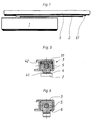
- die Ansicht einer prinzipiellen Anordnung eines obenliegenden Türschließers mit Türschließerarm und zugehöriger Gleitschiene,
- Fig. 2
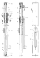
- einen Längsschnitt durch die Gleitschiene, bei der die Feststellvorrichtung außer Kraft ist,
- Fig. 3
- eine Darstellung entsprechend Fig. 2, in der die Feststellvorrichtung wirksam werden kann bei entsprechender Verschiebung des Türschließerarmes,
- Fig. 4
- eine Draufsicht auf die Darstellung in Fig. 2,
- Fig. 5
- einen Schnitt nach der Linie I - I in Fig. 2,
- Fig. 6
- einen Schnitt nach der Linie II - II in Fig. 2,
- Fig. 7
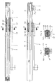
- einen Längsschnitt durch eine veränderte Gleitschiene mit modifizierter Feststellvorrichtung in der nichtfestgesetzten Stellung,
- Fig. 8
- eine Darstellung entsprechend Fig.7 in der festgesetzten Position,
- Fig. 9
- einen Schnitt nach der Linie III - III in Fig. 7 und
- Fig. 10
- einen Schnitt der Linie IV - IV in Fig. 8.
- Fig. 1
- the view of a basic arrangement of an overhead door closer with door closer arm and associated slide rail,
- Fig. 2
- a longitudinal section through the slide rail, in which the locking device is inoperative,
- Fig. 3
- 2 in which the locking device can take effect with a corresponding displacement of the door closer arm,
- Fig. 4
- 2 shows a top view of the illustration in FIG. 2,
- Fig. 5
- 2 shows a section along the line I - I in FIG. 2,
- Fig. 6
- 2 shows a section along the line II-II in FIG. 2,
- Fig. 7
- a longitudinal section through a modified slide rail with a modified locking device in the non-fixed position,
- Fig. 8
- a representation corresponding to Figure 7 in the fixed position,
- Fig. 9
- a section along the line III - III in Fig. 7 and
- Fig. 10
- a section of the line IV - IV in Fig. 8.
Zunächst wird auf die Figuren 1 - 6 Bezug genommen. An dem in Fig. 1 erkennbaren Türschließer bzw. dessen Gehäuse 1 ist der gelenkig mit dem im Gehäuse aufgenommenen Getriebe verbundene Türschließerarm 2 erkennbar, der in der türzargenseitig zu befestigenden Gleitschiene 3 mit seinem Ende geführt ist. Wie Fig. 2 zeigt, ist das entsprechende Ende des Türschließerarmes 2 gelenkig mit einem Gleitstück 4 verbunden, welches in der im Querschnitt C-förmigen, nach unten offenen Gleitschiene 3 geführt. Durch die in Fig. 5 erkennbare zylindrische Bohrung 41 des Gleitstückes 4 hindurch ist mit geringem Spiel eine im Querschnitt quadratische Stange 5 geführt, die an ihren Enden in den Endstopfen 32 und 33 der Gleitschiene 3 drehbar gelagert ist. Der Durchmesser der Bohrung 41 entspricht dabei etwa der Diagonale des Querschnittes der Stange 5.First, reference is made to FIGS. 1-6. 1, the door
An einem Ende weist diese Stange 5 ein um 45° verdrilltes Übergangsstück 51 auf. Eine Schiebehülse 6 ist mit einer entsprechenden Bohrung formschlüssig auf die Stange 5 aufgesetzt und in axialer Richtung von außen über das Griffelement 61 verschiebbar. Überfährt diese Schiebehülse 6 das Übergangsstück 51, So wird die Stange 5 jeweils um 45° verdreht. Durch diese Verschiebung der Schiebehülse 6 bzw. die sich ergebende Verdrehung der Stange 5 wird eine nachfolgend beschriebene Feststellvorrichtung betätigt.At one end, this
Im Gleitstück 4 ist in eine nach oben zur Gleitschienenwandung 31 hin offene Kammer 42 vorgesehen, in der formschlüssig, jedoch radial zur Drehachse der unrunden Stange 5 verschiebbar ein plattenartiges Blockierungselement 8 vorzugsweise aus Kunststoff aufgenommen ist. Dieses Blockierungselement 8 ruht auf der unrunden, vorzugsweise im Querschnitt quadratischen Stange 5. Beim Verdrehen der Stange 5 wird also dieses Blockierungselement 8 angehoben bzw. abgesenkt. In einem Schlitz 311 in Längsrichtung der Gleitschiene verschiebbar ist ein geringfügig in die Gleitschiene 3 hineinragendes Arretierungselement 7 vorgesehen. Bei entsprechender Verschiebung des Türschließerarmes 2 bzw. des daran angelenkten Gleitstückes 4 schiebt sich bei entsprechender Bemessung das in Fig. 3 dargestellte angehobene Blockierungselement 8 am Ende eines zu begrenzenden Führungsbereiches des Gleitstückes 4 gegen das Arretierungselement 7 und setzt sich daran fest. Der entstandene Reibschluß reicht aus, um die entsprechend geöffnete, nicht dargestellte Tür in der zugehörigen Öffnungslage festzusetzen. Durch Überwindung des Reibschlusses kann die Tür wieder in Schließrichtung gedrückt werden, wobei sich das Blockierungselement 8 vom Arretierungselement 7 löst.In the
Durch Verschiebung der Schiebehülse 6 aus der Position in Fig. 3 in die Position entsprechend Fig. 2, wobei sie das Übergangsstück 51 überfahren hat, wird die Stange 6 verdreht. Das Blockierungselement 8 ruht dann nicht mehr auf einer Kante der Stange sondern auf einer Flachseite und senkt sich ab. Damit ist die Feststellvorrichtung außer Kraft gesetzt. Das Gleitstück 4 kann ohne Berührung unter dem Arretierungselement 7 verschoben werden. Durch entsprechende Verschiebung der Schiebehülse 6 läßt sich die Feststellvorrichtung wieder aktivieren.By moving the sliding
Beim Ausführungsbeispiel nach den Figuren 7 - 10 ist lediglich die Einrichtung der Feststellvorrichtung geändert. Ihre Inkraftsetzung erfolgt in der gleichen Weise über die Verschiebung der Schiebehülse 6 und die damit verbundene Verdrehung der Stange 5. Auf dieser Stange mit dem endseitigen um 45° verdrillten Übergangsstück 51 ist in Achsrichtung einrichtbar ein Aufsatz 52 mit unrundem Querschnitt, vorzugsweise wiederum quadratisch, aufgesetzt. Seine Befestigung erfolgt beispielsweise mit zwei Klemmschrauben 53. Durch Verdrehung der Stange 5 wirkt bei entsprechendem Eingriff in das Gleitstück 104 durch die Bohrung 141 der Aufsatz 52 mit seinem Mantel gegen das im Gleitstück 104 in der nach oben offenen Kammer 142 formschlüssig aufgenommene, plattenartige Blockierungselement 108, welches wiederum vorzugsweise aus Kunststoff oder Gummi besteht. In der in den Figuren 8 und 10 dargestellten Feststellungsposition, die dem entsprechenden Feststellwinkel der geöffneten zugehörigen Tür entspricht, greift eine Kante des Aufsatzes 52 in die Kammer 142 hinein und drückt dabei am Ende eines zu begrenzenden Führungsbereiches des Gleitstücks 104 das Blockierungselement 108 klemmend gegen die Innenseite der oberen Gleitschienenwandung 131 der Gleitschiene 103, sodaß das Gleitstück 104 und damit auch der daran angebundene Türschließerarm festgesetzt ist. Durch Verdrehen der Stange 5 in die in den Figuren 7 und 9 dargestellten Position ist die Feststellvorrichtung außer Kraft.In the exemplary embodiment according to FIGS. 7-10, only the device of the locking device is changed. They come into effect in the same way via the displacement of the sliding
Claims (13)
- Overhead door closer, wherein a door closer arm (2) is guided in a slide rail (103) at the door frame end by means of a slider (104), which is pivotally connected to the door closer arm (2), and an adjustable mechanical device for adjusting the slider (104) in the slide rail (103) is provided for defining the guide range of the slide rail (103), characterised in that the adjustable device has such a configuration that a non-circular rod (5), which is mounted in the slide rail (103) and is rotatable from externally, is guided through the slider (104), a blocking element (108), which is securely accommodated in the slider (104) in the sliding direction of the slider (104), but is displaceable radially relative to the axis of rotation of the non-circular rod (5), being radially displaced during the rotation of said rod at the end of the guide range to he defined by means of an attachment (52), which is disposed on the non-circular rod (5), and being thereby securable against a slide rail wall (131).
- Overhead door closer, wherein a door closer arm (2) is guided in a slide rail (3) at the door frame end by means of a slider (4), Which is pivotally connected to the door closer arm (2), and an adjustable mechanical device for adjusting the slider (4) in the slide rail (3) is provided for defining the guide range of the slide rail (3), characterised in that the adjustable device has such a configuration that a non-circular rod (5), which is mounted in the slide rail (3) and is rotatable from externally, is guided through the slider (4), a blocking element (8), which is securely accommodated in the slider (4) in the sliding direction of the slider (4), hut is displaceable radially relative to the axis of rotation of the non-circular rod (5), being radially displaced during the rotation of said rod and being thereby securable against a locking element (7), which is disposed on a slide rail wall (31), at the end of the guide range to be defined.
- Door closer according to claim 1 or 2, characterised in that a transition member (51), which is twisted through about 45°, is provided in an end region of the non-circular rod (5), and a slidable sleeve (6), which is guided in the slide rail (3, 103), is axially displaceable via said transition member for the rotation of the rod (5).
- Door closer according to claim 1, characterised in that the non-circular rod (5) has a square cross-section and is guided through a cylindrical bore (141) in the slider (104), the blocking element (108), which is accommodated in the slider (104), being displaceable radially relative to the axis of rotation of the non-circular rod (5) in a direction towards the slide rail wall (131) at the end of the guide range to be defined by rotation of the rod (5).
- Door closer according to claim 2, characterised in that the non-circular rod (5) has a square cross-section and is guided through a cylindrical bore (41) in the slider (4), the locking element (7) being adjustable in the slide rail wall (31), in the longitudinal direction of the slide rail (3), and the blocking element (8), which is accommodated in the slider (4), being displaceable radially relative to the axis of rotation of the non-circular rod (5) in a direction towards this locking element (7) by rotation of the rod (5).
- Door closer according to claim 4 or 5, characterised in that the blocking clement (8, 108) is accommodated in a form-fitting manner in a chamber (42, 142) of the slider (4, 104), which chamber is upwardly open towards the upper slide rail wall (31, 131), and this chamber (42, 142) is open towards the axial, cylindrical bore (41, 141).
- Door closer according to claim 1 or 2, characterised in that the rod (5) is mounted by its ends in respective end stoppers (32, 33), which are inserted in the end faces of the slide rail (3, 103).
- Door closer according to claim 5, characterised in that the locking element (7) is displaceable in a slot (311) in the upper slide rail wall (131) in the longitudinal direction of the slide rail (3) and is securable by means of clamping screw connections.
- Door closer according to claim 1, characterised in that the attachment (52), which is disposed on the rod (5), has a square cross-section and is adjustable in the axial direction, the attachment (52) causing the radial displacement of the blocking element (108) at the end of the guide range to be defined towards the upper slide rail wall (131) during the rotation of the rod (5) in the slider (104).
- Door closer according to claim 3, characterised in that the slidable sleeve (6) is displaceable with a gripping element (61), which protrudes downwardly from the slide rail (3, 103).
- Door closer according to claim 3, characterised in that the slidable sleeve (6) is placed over the rod (5) in a form-fitting manner with a bore formed in the axial direction of the rod (5).
- Door closer according to claim 1, characterised in that the blocking element (8) is formed from plastics material arid co-operates with the slide rail wall (131) in the manner of a sliding coupling in the securement position in the event of excessive load on the door closer arm (2).
- Door closer according to claim 2, characterised in that the blocking element (8) is formed from plastics material and co-operates with the locking element (7) in the manner of a sliding coupling in the securement position in the event of excessive load on the door closer arm (2).
Applications Claiming Priority (2)
| Application Number | Priority Date | Filing Date | Title |
|---|---|---|---|
| DE4027532 | 1990-08-31 | ||
| DE19904027532 DE4027532C1 (en) | 1990-08-31 | 1990-08-31 |
Publications (2)
| Publication Number | Publication Date |
|---|---|
| EP0472916A1 EP0472916A1 (en) | 1992-03-04 |
| EP0472916B1 true EP0472916B1 (en) | 1995-09-13 |
Family
ID=6413281
Family Applications (1)
| Application Number | Title | Priority Date | Filing Date |
|---|---|---|---|
| EP19910112549 Expired - Lifetime EP0472916B1 (en) | 1990-08-31 | 1991-07-26 | Overhead door closer |
Country Status (2)
| Country | Link |
|---|---|
| EP (1) | EP0472916B1 (en) |
| DE (1) | DE4027532C1 (en) |
Families Citing this family (3)
| Publication number | Priority date | Publication date | Assignee | Title |
|---|---|---|---|---|
| EP0764752B1 (en) | 1995-09-23 | 2006-07-26 | GEZE GmbH | Device for closing the wing of a window, door or similar |
| WO2007069926A2 (en) * | 2005-12-14 | 2007-06-21 | Jacek Glogowski | Device for blocking or braking travel or rotational movement |
| DK2499317T3 (en) * | 2009-11-11 | 2015-04-20 | Vkr Holding As | Door or window brake device for door or window unit |
Family Cites Families (4)
| Publication number | Priority date | Publication date | Assignee | Title |
|---|---|---|---|---|
| GB1237941A (en) * | 1968-06-27 | 1971-07-07 | ||
| FR2036793A1 (en) * | 1969-04-01 | 1970-12-31 | Pigeon Jacques | |
| ZA821836B (en) * | 1981-03-30 | 1983-02-23 | Interlock Ind Ltd | Window of the like stays |
| DE3604083C2 (en) * | 1986-02-08 | 1996-04-04 | Dorma Gmbh & Co Kg | Locking device for door leaves with a door closer |
-
1990
- 1990-08-31 DE DE19904027532 patent/DE4027532C1/de not_active Expired - Fee Related
-
1991
- 1991-07-26 EP EP19910112549 patent/EP0472916B1/en not_active Expired - Lifetime
Also Published As
| Publication number | Publication date |
|---|---|
| EP0472916A1 (en) | 1992-03-04 |
| DE4027532C1 (en) | 1991-09-26 |
Similar Documents
| Publication | Publication Date | Title |
|---|---|---|
| EP1131521B1 (en) | Rotating-lock closure with traction unit | |
| EP1768874B1 (en) | Roof box with fixing device | |
| DE4292446C1 (en) | hinge | |
| EP3708753B1 (en) | Lid fitting for swingable mounting of a lid to a furniture unit | |
| EP1235967B1 (en) | Tape for doors, windows or the like | |
| DE2854713C2 (en) | ||
| DE3637077C1 (en) | Hinge joint for windows, doors or the like. | |
| EP0472916B1 (en) | Overhead door closer | |
| DE2949962C2 (en) | Hinge with locking mechanism | |
| EP0763641A1 (en) | Actuating device | |
| DE2900590A1 (en) | DOOR CLOSER | |
| EP0318422B1 (en) | Adjustable hinge, especially for doors | |
| WO2008132084A1 (en) | Door holding device for a motor vehicle door | |
| DE19745189C2 (en) | hinge | |
| DE19833612A1 (en) | Motorized drive for car body part which can pivot like door, hood or similar has friction pad pressed against drive element, i.e., drive pinion in spring-loaded fashion and fastened to motorized part, like support flange | |
| DE202005009745U1 (en) | fitting assembly | |
| EP0931897A1 (en) | Hinge with integral stop | |
| EP1936083A2 (en) | Support device for the hinge of a closing unit | |
| EP1640541A2 (en) | Device for stopping a swingable apparatus, in particular a door or window | |
| DE102015102757B4 (en) | fitting arrangement | |
| DE10130268B4 (en) | Locking system for vehicle doors | |
| EP0495198B1 (en) | Door check, especially for tilt and turn windows | |
| DE102005001706A1 (en) | Hinge with integrated locking mechanism | |
| DE202004004769U1 (en) | Metal fitting arrangement for rotating fanlight of e.g. window, has locking bar to lead detent from engaging position to releasing position, when locking bar moves from rotation release position to tipping position as fanlight moves | |
| EP0523401B1 (en) | Safety device for a door hinge structurally combined with a door check |
Legal Events
| Date | Code | Title | Description |
|---|---|---|---|
| PUAI | Public reference made under article 153(3) epc to a published international application that has entered the european phase |
Free format text: ORIGINAL CODE: 0009012 |
|
| 17P | Request for examination filed |
Effective date: 19910821 |
|
| AK | Designated contracting states |
Kind code of ref document: A1 Designated state(s): FR GB IT |
|
| R17P | Request for examination filed (corrected) |
Effective date: 19920813 |
|
| 17Q | First examination report despatched |
Effective date: 19930903 |
|
| GRAA | (expected) grant |
Free format text: ORIGINAL CODE: 0009210 |
|
| ITF | It: translation for a ep patent filed | ||
| AK | Designated contracting states |
Kind code of ref document: B1 Designated state(s): FR GB IT |
|
| GBT | Gb: translation of ep patent filed (gb section 77(6)(a)/1977) |
Effective date: 19951127 |
|
| ET | Fr: translation filed | ||
| PLBE | No opposition filed within time limit |
Free format text: ORIGINAL CODE: 0009261 |
|
| STAA | Information on the status of an ep patent application or granted ep patent |
Free format text: STATUS: NO OPPOSITION FILED WITHIN TIME LIMIT |
|
| 26N | No opposition filed | ||
| PGFP | Annual fee paid to national office [announced via postgrant information from national office to epo] |
Ref country code: GB Payment date: 19970530 Year of fee payment: 7 |
|
| PGFP | Annual fee paid to national office [announced via postgrant information from national office to epo] |
Ref country code: FR Payment date: 19970717 Year of fee payment: 7 |
|
| PG25 | Lapsed in a contracting state [announced via postgrant information from national office to epo] |
Ref country code: GB Free format text: LAPSE BECAUSE OF NON-PAYMENT OF DUE FEES Effective date: 19980726 |
|
| GBPC | Gb: european patent ceased through non-payment of renewal fee |
Effective date: 19980726 |
|
| PG25 | Lapsed in a contracting state [announced via postgrant information from national office to epo] |
Ref country code: FR Free format text: LAPSE BECAUSE OF NON-PAYMENT OF DUE FEES Effective date: 19990331 |
|
| REG | Reference to a national code |
Ref country code: FR Ref legal event code: ST |
|
| PG25 | Lapsed in a contracting state [announced via postgrant information from national office to epo] |
Ref country code: IT Free format text: LAPSE BECAUSE OF NON-PAYMENT OF DUE FEES Effective date: 20050726 |