EP0472832A2 - Einlassgitter für wasserstrahlangetriebene Boote - Google Patents
Einlassgitter für wasserstrahlangetriebene Boote Download PDFInfo
- Publication number
- EP0472832A2 EP0472832A2 EP91109623A EP91109623A EP0472832A2 EP 0472832 A2 EP0472832 A2 EP 0472832A2 EP 91109623 A EP91109623 A EP 91109623A EP 91109623 A EP91109623 A EP 91109623A EP 0472832 A2 EP0472832 A2 EP 0472832A2
- Authority
- EP
- European Patent Office
- Prior art keywords
- boat body
- water intake
- partition wall
- water
- transverse partition
- Prior art date
- Legal status (The legal status is an assumption and is not a legal conclusion. Google has not performed a legal analysis and makes no representation as to the accuracy of the status listed.)
- Withdrawn
Links
- XLYOFNOQVPJJNP-UHFFFAOYSA-N water Substances O XLYOFNOQVPJJNP-UHFFFAOYSA-N 0.000 claims abstract description 130
- 238000005192 partition Methods 0.000 claims abstract description 86
- 238000007667 floating Methods 0.000 claims abstract description 33
- 230000003405 preventing effect Effects 0.000 claims abstract description 14
- 239000000463 material Substances 0.000 claims description 6
- 238000001746 injection moulding Methods 0.000 claims description 5
- 229920006351 engineering plastic Polymers 0.000 claims description 4
- 229920001169 thermoplastic Polymers 0.000 claims description 3
- 239000004416 thermosoftening plastic Substances 0.000 claims description 3
- 241001474374 Blennius Species 0.000 description 5
- 238000010276 construction Methods 0.000 description 4
- 125000006850 spacer group Chemical group 0.000 description 4
- 230000000694 effects Effects 0.000 description 3
- 238000004519 manufacturing process Methods 0.000 description 3
- 238000011179 visual inspection Methods 0.000 description 3
- 229920002430 Fibre-reinforced plastic Polymers 0.000 description 2
- 238000005452 bending Methods 0.000 description 2
- 230000003247 decreasing effect Effects 0.000 description 2
- 239000011151 fibre-reinforced plastic Substances 0.000 description 2
- 239000004033 plastic Substances 0.000 description 2
- 229920003023 plastic Polymers 0.000 description 2
- 230000001105 regulatory effect Effects 0.000 description 2
- 229930182556 Polyacetal Natural products 0.000 description 1
- 230000001174 ascending effect Effects 0.000 description 1
- 238000004891 communication Methods 0.000 description 1
- 238000007688 edging Methods 0.000 description 1
- 229910001234 light alloy Inorganic materials 0.000 description 1
- 239000007769 metal material Substances 0.000 description 1
- 239000004431 polycarbonate resin Substances 0.000 description 1
- 229920005668 polycarbonate resin Polymers 0.000 description 1
- 229920006324 polyoxymethylene Polymers 0.000 description 1
- 229920005989 resin Polymers 0.000 description 1
- 239000011347 resin Substances 0.000 description 1
- 238000000638 solvent extraction Methods 0.000 description 1
- 239000002023 wood Substances 0.000 description 1
Images






Classifications
-
- B—PERFORMING OPERATIONS; TRANSPORTING
- B63—SHIPS OR OTHER WATERBORNE VESSELS; RELATED EQUIPMENT
- B63H—MARINE PROPULSION OR STEERING
- B63H11/00—Marine propulsion by water jets
- B63H11/02—Marine propulsion by water jets the propulsive medium being ambient water
Definitions
- Small-sized gliding boats of the jet-propelled type arranged for a single person to ride in a standing posture or some persons to ride in a seated posture have incorporated therein a jet-propelling device (or water jet pump) adapted to be driven for rotation by an engine mounted on the boat.
- a jet-propelling device or water jet pump
- Such jet propelling device is designed to draw water through a water intake port formed in the bottom surface of the boat body, accelerating said water by an impeller installed in a water intake duct (or pump case) to spout it rearwardly of the boat body, the reaction force serving as the propelling force for the boat body.
- the jet propelling device has the danger of drawing not only water but also garbage, seaweed, fishing lines and other various floating obstacles.
- a lattice called scope gate or grate is attached to the bottom surface of the boat body to cover said water intake port.
- the number of partition bars could be increased to partition the interior of the lattice more finely; it may be said that the more finely it is partitioned, the greater the effect attained. In that case, however, the amount of water that can be drawn in through the water intake port would also decrease, and the water flow would be bubbled or agitated.
- the present invention has been accomplished to solve these problems, and an object thereof is to provide an arrangement wherein to partition the water intake port formed in the bottom surface of the boat body, the scope gate for preventing floating obstacles from being drawn in is made in lattice form, comprising a pair of attaching seats by which it is attached to the boat body and a pair of longitudinal partition walls extending parallel with the travel center line of the boat body to bridge the space between said seats, the latter halves of said longitudinal partition walls extending downward by a fixed amount beyond the bottom surface of the boat body, a transverse partition wall disposed in said extending portions in an inclined state sloping rearwardly upward at a fixed angle, the lower surface of said transverse partition wall extending downward beyond the lower surface of the boat body, thereby arresting floating obstacles to prevent them from entering the water intake port in the boat body.
- Another object is to provide an arrangement wherein the transverse partition wall bridges the space between longitudinal partition walls in such a manner as to define a larger space between it and the front attaching seat and a smaller space between it and the rear attaching seat and is disposed in an inclined state sloping rearwardly upward at a fixed angle, whereby water is drawn in with no resistance through the water intake port such that the flow lines of water taken from the front larger space into the water intake port is dense and the flow rate is high while the flow lines of water taken from the rear smaller space into the water intake port is sparse and the flow rate is low, and the pressure in the smaller space is negative relative to that in the larger space, with the result that floating obstacles once arrested by the lower surface of the transverse partition wall are hardly drawn from the smaller space located therebehind into the water intake port and instead they are moved rearwardly of the boat body by the action of water flowing along the bottom surface of the boat body.
- the lattice of the scope gate is not of finely partitioned construction, so that water is smoothly guided from the water intake port in the boat body into the water intake duct without being excessively held back or being caused to bubble or being agitated, thus eliminating the possibility of cavitation taking place in the water intake duct, while allowing visual inspection of the interior of the water intake duct easily from outside and preventing garbage, seaweed, fishing lines and other various floating obstacles from being drawn in together with water.
- Such object can be attained by providing an arrangement wherein the longitudinal partition walls of the scope gate extending along the travel center line of the boat body are reduced in number to unity, substantially the latter half of such single longitudinal partition wall extending downward by a fixed amount beyond the bottom surface of the boat body, the extending latter half being bifurcated and sloping rearwardly upward at a fixed angle to provide a transverse partition wall, the front ends of the branches being continuous with the rear attaching seat, with the result that a pair of larger water intake spaces are defined between the transverse partition wall and the front attaching seat and a smaller water intake space is defined between the transverse partition wall and the rear attaching seat.
- the smaller water intake space is positioned rearwardly of the lower surface of the transverse partition wall where floating obstacles are once arrested, and the same as the above may be said about the interrelationship between the flow lines and flow rate of water drawn therefrom into the water intake port and those of water drawn from the larger spaces into the water intake port; thus, floating obstacles once arrested are positively pushed away rearwardly of the boat body along the bottom surface of the boat body by the water energy.
- the normal water drawing action at the water intake port of the boat body can be made further smooth and the scope gate itself can be further simplified.
- Another object of the invention is to provide an arrangement wherein the transverse partition wall is V- or U-shaped as seen in a bottom view such that it gradually extends forward as its center located on the travel center line of the boat body is approached, whereby floating obstacles once arrested by the lower surface of said transverse partition wall are efficiently pushed away rearwardly in two diverging directions so that they are prevented from entering the water intake port.
- a further object of the invention is to provide an arrangement wherein the scope gate is made by injection molding of a transparent or translucent engineering plastic material so that this injection molding, coupled with the employment of a construction in which the interior of the lattice is not finely partitioned, allows the interior thereof to be seen easily from outside, while even if floating obstacles should twine themselves around the impeller or the propeller shaft in the water intake duct, they can be efficiently removed, the scope gate being light in weight and adapted for mass production.
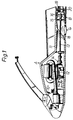
- Fig. 1 schematically showing a jet-propelled small-sized gliding boat in its entirety
- the character A generally denotes a boat body made of fiber-reinforced plastic (FRP), said boat body being of hollow sealed construction including a front region defined as an engine room 10 and a rear region with its upper surface defined as a floor deck 11 for a driver to ride in a standing posture. In some cases, the middle area of the floor deck 11 will be provided with a seat for a driver.
- the numeral 12 denotes an engine contained in the engine room 10 for driving a jet-propelling device (water jet pump) B through a propeller shaft 13 to impart a propelling force to the boat body A .
- a jet-propelling device water jet pump
- the propeller shaft 13 extends along the travel center line O-O of the boat body A to a position below the floor deck 11 and is connected at its front end to the crank shaft (not shown) of the engine 12 through a clutch 14. Integrally rotatably connected to the rear end of the propeller shaft 13 are an impeller 15 and guide vanes 16.
- the numeral 17 denotes a water intake duct serving as a pump case for receiving the impeller 15 and guide vanes 16, said water intake duct being disposed below the floor deck 11, with its front side providing a water intake port 18 which opens in the middle of the bottom surface of the boat body A .
- the steering nozzle 19 is manually controlled from the floor deck 11 to change its direction, whereby the boat body A can be steered.
- the numeral 20 denotes a pump case cover attached to the middle region of the bottom surface of the boat body A .
- the scope gate G is made of a light alloy or transparent or translucent polycarbonate resin, polyacetal resin or other thermoplastic engineering plastic material preferably having high bending elasticity into the form of an elongated lattice.
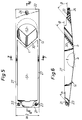
- the numerals 21 and 22 denote a pair of attaching seats having a width w2 smaller than the width w1 of said water intake port 18.
- the front attaching seat 21 has a pair of bolt receiving holes 23 on opposite sides, while the rear attaching seat 22 is centrally formed with a bolt receiving hole 24 which preferably is elongated in the longitudinal direction.
- the number and disposition of bolt receiving holes 23 and 24 may be freely changed in connection with the boat body A .
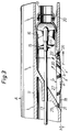
- the attaching seats 21 and 22 are applied at their flat surfaces to the bottom surface of the boat body A and then, as shown in Figs. 2 and 3, fixed thereto by a plurality of stud bolts 25 and 26 so that the scope gate G can be removed or exchanged.
- the open edges of the attaching seats 21 and 22 of the scope gate G opposed to the interior of the lattice are formed as slope surfaces rearwardly ascending at given angles ⁇ and ⁇ with respect to the horizontal surface.
- the numeral 27 denotes a pair of flow regulating longitudinal walls spanning the space between the attaching seat 21 and 22 and extending parallel with the travel center line O-O of the boat body A to partition the water intake port 18 of the boat body A with the lateral surfaces thereof being approximately orthogonal to the attaching surfaces of said seats 21 and 22.
- the walls have been referred to as the "longitudinal partition walls".
- the longitudinal partition walls 27 can be transversely deformed as if they were plate springs during the turning of the boat body A .
- the longitudinal partition walls 27 of the scope gate G are subjected to the water pressure acting thereon and are thereby elastically deformed transversely to and fro, thus allowing water to flow without being held back or disturbed; thus, water is smoothly drawn in through the water intake port 18. For this reason, the cavitation in the water intake duct 17 is effectively suppressed.
- the cross-sections of the longitudinal partition walls 27 are preferably in the form of a basic triangle or trapezoid with its thickness gradually decreasing upward, as suggested in Fig. 7. That is, the surfaces of the longitudinal partition walls 27 are formed as slope surfaces with the thickness gradually decreasing upward.
- the character ⁇ suggests the crossing angle between the forwardly and rearwardly upward slope surfaces.
- the intermediate regions a remotest from the pair of attaching seats 21 and 22 can be physically reinforced to be free from damage thereto.
- the front halves of the longitudinal partition walls 27 have their lower surfaces designed to define forwardly upward slope surfaces; therefore, the boat body A can be given lift by water acting on said surfaces.
- the scope gate G of the present invention is adapted to be fixed at said attaching seats 21 and 22 to the bottom surface of the boat body A such that the rear portions of the longitudinal partition walls 27 project by a fixed amount h downward beyond the lower surface of the boat body A .
- a spacer 28 shown in Fig. 8 is preferably interposed between the rear attaching seat 22 and the bottom surface of the boat body A so as to adjust said amount of projection h .
- the spacer 28 is shaped to correctly fit on the rear attaching seat 22 of the scope gate G ; thus, it is applied to the rear attaching seat 22 for attachment to the bottom surface of the boat body A by said stud bolt 26 through a communication hole 29 aligned with a bolt receiving hole 24, thereby increasing the amount of projection h . It is possible to decrease the amount of projection h by removing the spacer 28.
- the numeral 30 denotes a transverse partition wall transversely extending between the intermediate portions of the longitudinal partition walls 27, thereby dividing the interior of the lattice of the scope gate G into a front, larger water intake space S1 and a rear, smaller water intake space S2. That is, the larger space S1 is located between the front attaching seat 21 and the transverse partition wall 30, while the smaller space S2 is located between the transverse partition wall 30 and the rear attaching seat 22.
- the surface of the transverse partition wall 30 is formed as a rearwardly upward slope surface crossing the horizontal surface at a fixed angle ⁇ to be substantially parallel with the edges of the openings in the attaching seats 21 and 22, so that water is smoothly guided from the water intake port 18 of the boat body A into the water intake duct 17.
- the scope gate G is curved in V- or U-shape gradually extending forward as the center c positioned on the travel center line O-O is approached.
- the lower surface b of the transverse partition wall 30 projects downward beyond the bottom surface of the boat body A as described above, floating obstacles, while being arrested, are moved in two diverging directions laterally of the boat body A ; thus, their accidental entry into the water intake port 18 is effectively prevented.
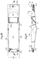
- transverse partition wall 30 is an inclined surface sloping rearwardly upward at a fixed angle ⁇ with its lower surface b projecting downward beyond the bottom surface of the boat body A to be exposed, use may be made of a scope gate G shown in Figs. 9 through 11, which is a first modified embodiment, having a transverse partition wall 30a which is straight as seen in a bottom view and which is orthogonal to its longitudinal partition walls 27a.
- Figs. 12 through 15 show a second modified embodiment of a scope gate G according to the present invention, wherein a single longitudinal partition wall 27b is positioned on the travel center line O-O of the boat body A and extends between the attaching seats 21b and 22b, and the rear end of said longitudinal partition wall 27b is bifurcated to provide a transverse partition wall 30b, the front ends of the resulting branches being connected to the opposite sides of the rear attaching seat 22b, whereby a smaller space S2 for water intake is defined between the transverse partition wall 30b and the rear attaching seat 22b.
- the larger space S1 for water intake defined between the front attaching seat 21b and the transverse partition wall 30b is bisected by the single longitudinal partition wall 27b. However, regardless of this bisection, it still opens wider than the smaller space S2.
- the functions of the scope gate G will now be described on the basis of the basic embodiment shown in Figs. 4 through 7.
- the scope gate G is fixed to the bottom surface of the boat body A to partition the water intake port 18 of the boat body such that substantially the latter halves of the pair of longitudinal partition walls 27 project downward by a fixed amount h beyond the bottom surface of the boat body A ; therefore, a sideslip preventing effect (so-called edging effect) can be attained during the turning of the boat body A . Further, if the boat body runs on shallows or on drifting wood, its bottom surface will not hit the same and hence damage thereto is avoided.
- the transverse partition wall 30 is disposed to assume an inclined state sloping rearwardly upward at a fixed angle ⁇ , whereby the smaller space S2 for water intake is defined between the transverse partition wall 30 and the rear attaching seat 22; therefore, without having to finely partition the scope gate G itself, it can be physically reinforced by the transverse partition wall 30 and the entry of garbage, seaweed and other various floating obstacles through the water intake port 18 is prevented.
- the latter halves of the longitudinal partition walls 27 project downward by a fixed amount h and the lower surface b of the transverse partition wall 30 disposed in the intermediate portions of said longitudinal partition walls also projects downward beyond the bottom surface of the boat body A .
- floating obstacles once arrested thereat are pushed away rearwardly of the boat body A by water flowing in the direction y without entering the water intake port 18.
- the transverse partition wall 30 disposed in an inclined state sloping rearwardly upward at the fixed angle ⁇ divides the interior of the lattice of the scope gate G into the front larger space S1 for water intake and the rear smaller space S2 for water intake; therefore, whereas the flow lines of water moving in the direction x from the front larger space S1 are dense and the flow rate is high, so that the water is drawn into the water intake port 18 without any resistance, the flow line of water moving in the dotted-line direction x from the rear smaller space S2 are sparse and the flow rate is low and the pressure is negative relative to that in the larger space S1, with the result that floating obstacles once arrested by the lower surface b of the transverse partition wall 30 are hardly drawn from the smaller space S2 located therebehind into the water intake port 18 and instead they are reliably moved rearwardly of the boat body A by the action of water flowing in the direction y .
- transverse partition wall 30 or 30b are V- or U-shaped as seen from the bottom surface of the boat body A gradually extending forward toward the center c located on the travel center line O-O of the boat body A and are curved in transversely bifurcated skirt form, then said floating obstacles will be pushed away along such curved surface in two diverging directions obliquely rearwardly of the boat body A , so that the entry of said floating obstacles through the water intake port 18 can be prevented.
- the interior of the scope gate G of the present invention does not have to be finely partitioned and hence the sufficient amount of water to be drawn in can be obtained also during the turning of the boat body A without disturbing the water flow, and yet the entry of floating obstacles can be reliably prevented. Furthermore, the required arrangement is very simple. The technical significance and value of the invention lie in these points.
- the invention provides a device used in jet-propelled gliding boats for preventing floating obstacles from being drawn in, wherein a scope gate G for preventing entry of floating obstacles is attached to a water intake port 18 formed in the bottom surface of the boat body, and the water drawn from the water intake port 18 is accelerated by an impeller 15 housed in a water intake duct 17 and spouted rearwardly of the boat body A , said device being characterized in that as shown in the basic embodiment of Figs. 4 through 7 and the first modified embodiment of Figs.
- said scope gate G is in lattice form composed of a pair of attaching seats 21, 21a or 22, 22a associated with the bottom surface of the boat body A and a pair of longitudinal partition walls 27 and 27a extending parallel with the travel center line O-O of the boat body A to interconnect said attaching seats, substantially the latter halves of said longitudinal partition walls 27 and 27a project downward by a fixed amount h beyond the bottom surface of the boat body A , while a transverse partition wall 30 or 30a is disposed in the intermediate portions of the projecting latter halves to assume an inclined state sloping rearwardly upward at a fixed angle ⁇ , whereby a larger space S1 for water intake is defined between the transverse partition wall 30 or 30a and the front attaching seat 21 or 21a and a smaller space S2 for water intake is defined between the transverse partition wall 30 or 30a and the rear attaching seat 22 or 22a. Therefore, as described with reference to Fig. 3, garbage, seaweed and other floating obstacles can be reliably prevented from entering through the water intake port 18 of
- transverse partition wall 30 or 30b is V- or U-shaped as seen in a bottom view gradually projecting forward toward the center c located on the travel center line O-O of the boat body A and is curved in transversely bifurcated skirt form, floating obstacles can be pushed away more efficiently along the curved surface obliquely rearwardly of the boat body A ; thus, their entry through the water intake port 18 can be prevented, while normal water can be guided into the water intake port 18 without any resistance.
- the entire scope gate G is integrally made by injection molding of a transparent or translucent thermoplastic engineering plastic material, as described in Claim 4, then this arrangement, coupled with the construction in which the interior of the scope gate G is not finely partitioned, allows easily visual inspection of the interior of the water intake duct 17 from the water intake port 18. If floating obstacles should enter the water intake ducts 17 and twine themselves around the impeller or the propeller shaft, they can be easily and efficiently removed. Further, the scope gate is suitable for mass production and is light in weight.
Landscapes
- Chemical & Material Sciences (AREA)
- Engineering & Computer Science (AREA)
- Combustion & Propulsion (AREA)
- Mechanical Engineering (AREA)
- Ocean & Marine Engineering (AREA)
- Barrages (AREA)
- Excavating Of Shafts Or Tunnels (AREA)
Applications Claiming Priority (1)
| Application Number | Priority Date | Filing Date | Title |
|---|---|---|---|
| JP20361490A JPH0487898A (ja) | 1990-07-30 | 1990-07-30 | ジエツト推進式滑走艇における障害物の吸入防止装置 |
Publications (2)
| Publication Number | Publication Date |
|---|---|
| EP0472832A2 true EP0472832A2 (de) | 1992-03-04 |
| EP0472832A3 EP0472832A3 (en) | 1992-06-03 |
Family
ID=16476961
Family Applications (1)
| Application Number | Title | Priority Date | Filing Date |
|---|---|---|---|
| EP19910109623 Withdrawn EP0472832A3 (en) | 1990-07-30 | 1991-06-12 | Intake grating for water-jet propelled boats |
Country Status (3)
| Country | Link |
|---|---|
| EP (1) | EP0472832A3 (de) |
| JP (1) | JPH0487898A (de) |
| AU (1) | AU8136491A (de) |
Cited By (3)
| Publication number | Priority date | Publication date | Assignee | Title |
|---|---|---|---|---|
| US5234361A (en) * | 1992-11-10 | 1993-08-10 | Glenn Dickinson | Foiled grating for jet watercraft |
| US6855019B2 (en) * | 2001-09-18 | 2005-02-15 | Honda Giken Kogyo Kabushiki Kaisha | Jet propulsion watercraft |
| CN108189994A (zh) * | 2018-02-06 | 2018-06-22 | 上海丞士机器人有限公司 | 一种双面吸水的喷水推进泵 |
Families Citing this family (1)
| Publication number | Priority date | Publication date | Assignee | Title |
|---|---|---|---|---|
| US7062049B1 (en) * | 1999-03-09 | 2006-06-13 | Honda Giken Kogyo Kabushiki Kaisha | Active noise control system |
Family Cites Families (4)
| Publication number | Priority date | Publication date | Assignee | Title |
|---|---|---|---|---|
| US4237812A (en) * | 1978-09-28 | 1980-12-09 | Richardson Jerald S | Jet ski grating |
| US4373919A (en) * | 1980-11-17 | 1983-02-15 | Rockwell International Corporation | Multi-passage variable diffuser inlet |
| US4775341A (en) * | 1986-07-09 | 1988-10-04 | Wetco Industries | Foil system for jet propelled aquatic vehicle |
| US4925408A (en) * | 1987-09-14 | 1990-05-15 | Koronis Parts, Inc. | Intake and pump assembly for aquatic vehicle |
-
1990
- 1990-07-30 JP JP20361490A patent/JPH0487898A/ja active Pending
-
1991
- 1991-06-12 EP EP19910109623 patent/EP0472832A3/en not_active Withdrawn
- 1991-07-25 AU AU81364/91A patent/AU8136491A/en not_active Abandoned
Cited By (5)
| Publication number | Priority date | Publication date | Assignee | Title |
|---|---|---|---|---|
| US5234361A (en) * | 1992-11-10 | 1993-08-10 | Glenn Dickinson | Foiled grating for jet watercraft |
| US5281177A (en) * | 1992-11-10 | 1994-01-25 | Glenn Dickinson | Foiled grating for jet watercraft |
| US6855019B2 (en) * | 2001-09-18 | 2005-02-15 | Honda Giken Kogyo Kabushiki Kaisha | Jet propulsion watercraft |
| CN108189994A (zh) * | 2018-02-06 | 2018-06-22 | 上海丞士机器人有限公司 | 一种双面吸水的喷水推进泵 |
| CN108189994B (zh) * | 2018-02-06 | 2023-12-26 | 上海丞士机器人有限公司 | 一种双面吸水的喷水推进泵 |
Also Published As
| Publication number | Publication date |
|---|---|
| JPH0487898A (ja) | 1992-03-19 |
| AU8136491A (en) | 1992-02-06 |
| EP0472832A3 (en) | 1992-06-03 |
Similar Documents
| Publication | Publication Date | Title |
|---|---|---|
| AU732970B2 (en) | High efficiency hydrofoil and swim fin designs | |
| EP0361149A1 (de) | Kleinboot mit Düsenantrieb | |
| US6482059B2 (en) | High efficiency hydrofoil and swim fin designs | |
| US4928983A (en) | Snow glider | |
| DE69027455T2 (de) | Wasserstrahlantriebseinheit | |
| US4945852A (en) | Compact planning type boat | |
| US4003325A (en) | Cargo vessel low resistance bow | |
| US6371821B1 (en) | High efficiency hydrofoil and swim fin designs | |
| EP0472832A2 (de) | Einlassgitter für wasserstrahlangetriebene Boote | |
| US4737127A (en) | Hydrodynamic swim fin | |
| US3280786A (en) | Hydroscooter | |
| US6007393A (en) | Surfboard | |
| US4276035A (en) | Duct systems for water jet propulsion boats | |
| US5700169A (en) | Inlet adapter for a personal watercraft | |
| US3726249A (en) | Water craft | |
| US1918508A (en) | Water sled or surf board | |
| EP0465908A1 (de) | Wassereinlass- und -leitvorrichtung für strahlangetriebene Gleitboote | |
| DE69517635T2 (de) | Hochleistungs-motorwasserski | |
| JPH0717675Y2 (ja) | ジエツト推進式滑走艇の横滑り防止装置 | |
| CA2044350A1 (en) | Device used in jet-propelled gliding boats for preventing floating obstacles from being drawn in | |
| RU2176608C2 (ru) | Быстроходное судно | |
| DE3320331A1 (de) | Hochgeschwindigkeitssegelbrett | |
| US5344346A (en) | Driveshaft housing attachment | |
| US3353293A (en) | Try net trawl doors | |
| US4768453A (en) | Watercraft |
Legal Events
| Date | Code | Title | Description |
|---|---|---|---|
| PUAI | Public reference made under article 153(3) epc to a published international application that has entered the european phase |
Free format text: ORIGINAL CODE: 0009012 |
|
| AK | Designated contracting states |
Kind code of ref document: A2 Designated state(s): BE DE DK FR GB IT NL SE |
|
| PUAL | Search report despatched |
Free format text: ORIGINAL CODE: 0009013 |
|
| AK | Designated contracting states |
Kind code of ref document: A3 Designated state(s): BE DE DK FR GB IT NL SE |
|
| STAA | Information on the status of an ep patent application or granted ep patent |
Free format text: STATUS: THE APPLICATION IS DEEMED TO BE WITHDRAWN |
|
| 18D | Application deemed to be withdrawn |
Effective date: 19921204 |