EP0472801A1 - Verfahren und Vorrichtung zum Auffinden eines Endes eines Magnetbands, das auf einer Spule in einem automatischen Kassettenladegerät aufgewickelt ist - Google Patents
Verfahren und Vorrichtung zum Auffinden eines Endes eines Magnetbands, das auf einer Spule in einem automatischen Kassettenladegerät aufgewickelt ist Download PDFInfo
- Publication number
- EP0472801A1 EP0472801A1 EP90830383A EP90830383A EP0472801A1 EP 0472801 A1 EP0472801 A1 EP 0472801A1 EP 90830383 A EP90830383 A EP 90830383A EP 90830383 A EP90830383 A EP 90830383A EP 0472801 A1 EP0472801 A1 EP 0472801A1
- Authority
- EP
- European Patent Office
- Prior art keywords
- reel
- pancake
- reading member
- closure tab
- rotation
- Prior art date
- Legal status (The legal status is an assumption and is not a legal conclusion. Google has not performed a legal analysis and makes no representation as to the accuracy of the status listed.)
- Granted
Links
Images

Classifications
-
- G—PHYSICS
- G11—INFORMATION STORAGE
- G11B—INFORMATION STORAGE BASED ON RELATIVE MOVEMENT BETWEEN RECORD CARRIER AND TRANSDUCER
- G11B23/00—Record carriers not specific to the method of recording or reproducing; Accessories, e.g. containers, specially adapted for co-operation with the recording or reproducing apparatus ; Intermediate mediums; Apparatus or processes specially adapted for their manufacture
- G11B23/02—Containers; Storing means both adapted to cooperate with the recording or reproducing means
- G11B23/113—Apparatus or processes specially adapted for the manufacture of magazines or cassettes, e.g. initial loading into container
-
- G—PHYSICS
- G11—INFORMATION STORAGE
- G11B—INFORMATION STORAGE BASED ON RELATIVE MOVEMENT BETWEEN RECORD CARRIER AND TRANSDUCER
- G11B15/00—Driving, starting or stopping record carriers of filamentary or web form; Driving both such record carriers and heads; Guiding such record carriers or containers therefor; Control thereof; Control of operating function
- G11B15/02—Control of operating function, e.g. switching from recording to reproducing
- G11B15/05—Control of operating function, e.g. switching from recording to reproducing by sensing features present on or derived from record carrier or container
- G11B15/06—Control of operating function, e.g. switching from recording to reproducing by sensing features present on or derived from record carrier or container by sensing auxiliary features on record carriers or containers, e.g. to stop machine near the end of a tape
- G11B15/08—Control of operating function, e.g. switching from recording to reproducing by sensing features present on or derived from record carrier or container by sensing auxiliary features on record carriers or containers, e.g. to stop machine near the end of a tape by photoelectric sensing
Definitions
- the present invention relates to a process and apparatus for finding one end in a magnetic tape wound onto a reel in automatic cassette loading machines, the tape end being fastened to the reel by a closure tab having a free end portion oriented outwardly to the reel itself.
- the apparatus of the invention is of the type comprising a support hub operable in rotation and adapted to operatively engage a magnetic tape reel, commonly referred to as "pancake".
- the process and apparatus in question are conceived for suitably arranging the end of a tape wound onto a pancake so that it may be picked up by automatic means designed to engage and guide it according to a predetermined path between the different members of a cassette loading machine.
- the loading machines should be associated with means adapted to automatically pick up the tape end from the new pancake mounted on the hub and guide the tape between the different loading machine members as far as it reaches the cassette loading station.
- the apparatus for picking up the use tape and engaging it in the different members of the cassette loading machine can perform its functions only if the pancake after being mounted on the hub is disposed in such a manner that the end of the tape wound thereon is located at a predetermined point from which it can be easily picked up by a grasping element associated with the apparatus itself. Since at the mounting of the pancake on the hub the position of the tape end is completely casual, the apparatus for picking up the tape must be assisted by means capable of finding the tape end on the circumferential extension of the pancake and consequently dispose the pancake so that said tape end may be located at the most appropriate position.
- the technical problem to be solved consists in making the operation of finding the tape end and subsequently positioning it at the right place very quick and reliable, independently of the diameter of the pancake.
- the main object of the present invention is therefore to solve the above technical problem by providing a process and an apparatus adapted to completely meet the above requirements.
- a process for finding the end of a magnetic tape wound onto a pancake in automatic cassette loading machines characterized in that it comprises the following steps: mounting the pancake on a support hub; positioning a reading member at a location diametrically spaced apart from the pancake; moving the reading member close to the pancake until the peripheral edge of the pancake is intercepted by the reading member; moving away the reading member a predetermined amount from the pancake; driving in rotation the pancake; stopping the pancake rotation as soon as the reading member intercepts the closure tab in order to dispose said tab to a predetermined position.
- an apparatus for finding the end of a magnetic tape wound onto a pancake in automatic cassette loading machines characterized in that it comprises: a main carriage movable according to a direction at right angles to the pancake axis; a reading member operatively supported by the main carriage and adapted to be moved, as a result of the movement of the carriage itself, close to and away from the pancake so that it may intercept the closure tab and stop the pancake rotation when the closure tab is in a predetermined position.
- an apparatus for finding the end of a magnetic tape wound onto a pancake in automatic cassette loading machines in accordance with the present invention has been generally identified by reference numeral 1.
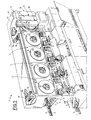
- apparatus 1 is associated with an automatic cassette loading machine generally referenced by 2 in Fig. 1. Only the essential parts of the machine will be briefly described herein as the machine has already been widely disclosed in another Italian Patent Application filed on the same date in the name of the same Applicant.
- the machine 2 has a number of loading modules 3 disposed in side by side relation and in mutual alignment, to which a plurality of cassettes 5 are sent by a supply conveyor 4. Each cassette will be loaded with a predetermined amout of magnetic tape 8.
- Each loading module 3 has a loading station 6 in which the cassettes 5 coming from a respective infeed conveyor 7 connected to the supply conveyor 4 are engaged one at a time in order to be loaded with the magnetic tape 8 continuously fed from a respective pancake 9 operatively mounted on a support hub 10 operable in rotation in a manner known per se and conventional.
- the cassette 5 is released from the loading station 6 and removed from the machine 2 through a discharge chute 11 a terminating in a discharge conveyor 11.
- a manipulating unit generally identified by 12 When one of said pancakes 9 is out of tape 8, a manipulating unit generally identified by 12 is operated through sensor means known per se and said manipulating unit removes the empty pancake and replaces it with a new pancake provided with tape 8 which in turn has been taken from a supply magazine 15 located sideways to the loading modules 3 and carrying a plurality of tape loaded pancakes 9.
- the manipulating unit 12 comprises a main carriage 13 horizontally movable along respective guide bars 14, in a direction at right angles to the axis of the pancakes 9 mounted on the respective hubs 10.
- the movements of the main carriage 13 take place upon command of a worm screw 16 driven by a motor 17 controlled by a conventional encoder 17a.
- the manipulating unit 12 is also provided with a pick-up module 18 designed to pick up the individual pancakes 9 from a supply magazine 15.
- the manipulating unit 12 is moved along the guide bars 14 so that it comes into register with the loading module 3 in which the pancake 9 need to be replaced.
- a discharge module 20 disposed in side by side relation relative to the pick-up module 18 automatically removes the out of tape pancake 9 from the respective support hub 10.
- the manipulating unit 12 is again moved forward along the guide bars 14 over a short length thereof, so that said pick-up module 18 is brought in front of the hub 10 and it can fit the new pancake 9 provided with use tape 8 on the hub itself.
- each pancake 9 located in the supply magazine 15 has one end 8a of the respective tape 8 secured to the pancake itself by means of a closure tab 22.
- this closure tab 22 conventionally has an adhesive portion 22a by which the fastening of the end 8a to the pancake is carried out, as well as a free portion 22b oriented outwardly to the pancake itself.
- the respective closure tab 22 When the pancake 9 has been engaged on the respective support hub 10, the respective closure tab 22 is randomly located at any point on the circunferential extension of the pancake itself. However it is necessary that said closure tab 22 be disposed according to a predetermined positioning so that its free portion 22b may be easily picked up by a grasping member 23 associated with a setup module 24 being part of the manipulating unit 12.
- Said grasping member 23 is movable in a vertical direction upon command of one or more fluid-operated cylinders 25a, 25b so that it causes the end 8a of the tape 8 it holds to travel according to a predetermined path between the different members of the corresponding loading module 3, simultaneously with the displacements of the main carriage 13 along the guide bars 14.
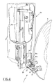
- a reading member 26 is provided which is fastened at the lower part thereof to a support arm 27 being part of the setup module 24 and extending vertically downwardly from the main carriage 13.
- the support arm 27 is connected to the main carriage 13 by a pair of guide bars 28 allowing said arm to move upon command of a fluid-operated actuator 29 parallelly to the axes of the pancakes 9.
- the reading member 26 is shifted from a rest position in which it is axially spaced apart from the pancakes 9 so that it does not interfere with the support hubs 10 when the main carriage 13 is moved, to an operating condition in which it substantially operates in the same lying plane as the pancake 9 mounted to the respective support hub 10.
- the reading member 26 comprises a photoelectric cell 30 provided with a photoemitter 30a designed to emit a light beam shown in dotted lines and referenced by "L", suitably inclined relative to the axis of the pancake 9, as well as with a photoreceiver 30b facing the photoemitter 30a so as to receive the light beam "L” emitted by the latter.
- the angle of inclination of the light beam “L” relative to the axis of the pancake 9 is provided to have a value in the range of 30 to 60 and it is preferably equal to 45 ⁇ .
- the photoemitter 30a and photoreceiver 30b are located at the opposite ends 31 a of a fork-shaped element 31 which between its ends defines a housing 32 adapted to be engaged by the outer peripheral edge of the pancake 9.
- the grasping member 23 when at rest.
- operation of the apparatus 1 is as follows.
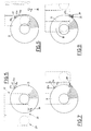
- the main carriage 13 is moved along the guide bars 14 under the control of said encoder 13a so that the reading member 26 takes a diametrical position relative to the pancake 9 being moved apart therefrom, as shown in Fig. 6.
- the distance between the reading member 26 and the axis of the pancake is provided to be higher than the value of the maximum radius offered by the pancakes 9 used in the loading machine 2.
- the step for finding the peripheral edge of the pancake 9 is about to start. To this end the main carriage 13 is moved along the guide bars 14 so that the reading member 26 is moved close to the pancake 9 at right angles to the axis of the pancake itself. Under this situation within a more or less short period of time depending upon the diameter of the pancake 9, the peripheral edge of said pancake will be introduced into the housing 32 defined between the ends 31 a of the fork-shaped element 31. As a result, the photoelectric cell 30 will detect the breaking of the light beam "L" emitted by the photoemitter 30 and will command the reverse movement of the carriage 13. In greater detail, the carriage 13 is moved so that the reading member 26 is again diametrically moved away from the pancake 9 by a predetermined amount.
- Said distance must be sufficient to enable the light beam "L” to be intercepted by the free portion 22b of the closure tab 22 when the latter passes between the photoemitter 30a and the photoreceiver 30b as a result of a rotation imparted to the pancake 9 by the hub 10.
- the photoelectric cell will stop the rotation of the pancake 9 and the free end 22b will be therefore disposed in that predetermined position enabling its being picked up by the grasping member 23.
- the starting of rotation of the pancake 9 is provided to occur simultaneously with the positioning of the reading member 26 to its working position, that is before the beginning of the step in which the reading member is moved close to the pancake for detecting the peripheral edge of the latter.
- the new moving away of the reading member 26 from the pancake 9 will occur after said pancake has carried out at least a rotation about its own axis starting from the moment at which the interception of the light beam "L" has taken place.
- the present invention attains the intended purposes.
Landscapes
- Replacement Of Web Rolls (AREA)
- Auxiliary Devices For And Details Of Packaging Control (AREA)
- Spinning Or Twisting Of Yarns (AREA)
- Indexing, Searching, Synchronizing, And The Amount Of Synchronization Travel Of Record Carriers (AREA)
- Wrapping Of Specific Fragile Articles (AREA)
Applications Claiming Priority (2)
| Application Number | Priority Date | Filing Date | Title |
|---|---|---|---|
| IT02122690A IT1246430B (it) | 1990-08-06 | 1990-08-06 | Procedimento e dispositivo per la ricerca di un capo di un nastro magnetico avvolto su una bobina in macchine automatiche confezionatrici di cassette a nastro |
| IT2122690 | 1990-08-06 |
Publications (2)
| Publication Number | Publication Date |
|---|---|
| EP0472801A1 true EP0472801A1 (de) | 1992-03-04 |
| EP0472801B1 EP0472801B1 (de) | 1995-01-11 |
Family
ID=11178680
Family Applications (1)
| Application Number | Title | Priority Date | Filing Date |
|---|---|---|---|
| EP90830383A Expired - Lifetime EP0472801B1 (de) | 1990-08-06 | 1990-08-28 | Verfahren und Vorrichtung zum Auffinden eines Endes eines Magnetbands, das auf einer Spule in einem automatischen Kassettenladegerät aufgewickelt ist |
Country Status (7)
| Country | Link |
|---|---|
| US (1) | US5121886A (de) |
| EP (1) | EP0472801B1 (de) |
| JP (1) | JPH0634340B2 (de) |
| AT (1) | ATE117122T1 (de) |
| DE (1) | DE69016020T2 (de) |
| ES (1) | ES2069727T3 (de) |
| IT (1) | IT1246430B (de) |
Families Citing this family (4)
| Publication number | Priority date | Publication date | Assignee | Title |
|---|---|---|---|---|
| US5340049A (en) * | 1990-08-06 | 1994-08-23 | Tapematic U.S.A., Inc. | Method and apparatus for finding one end of tape wound onto a reel |
| IT1246431B (it) * | 1990-08-06 | 1994-11-18 | Tapematic Spa | Dispositivo per afferrare e guidare secondo un percorso prefissato un nastro magnetico avvolto su una bobina in macchine automatiche confezionatrici di cassette a nastro |
| DE4117386A1 (de) * | 1991-05-28 | 1992-12-03 | Agfa Gevaert Ag | Verfahren und vorrichtung zum erfassen des filmanfangs eines aufgewickelten films |
| US5483877A (en) * | 1992-10-02 | 1996-01-16 | Tapematic U.S.A., Inc. | Cassette stacker/stamper |
Citations (3)
| Publication number | Priority date | Publication date | Assignee | Title |
|---|---|---|---|---|
| US3643889A (en) * | 1969-07-22 | 1972-02-22 | Konrad A Krause | Automatic tape-threading system and apparatus |
| FR2353112A1 (fr) * | 1976-05-28 | 1977-12-23 | Sony Corp | Appareil pour la fabrication de cassettes a ruban magnetique |
| EP0281884A2 (de) * | 1987-03-10 | 1988-09-14 | Luciano Perego | Kassettenladegerät und Arbeitsverfahren |
Family Cites Families (6)
| Publication number | Priority date | Publication date | Assignee | Title |
|---|---|---|---|---|
| CA1077618A (en) * | 1975-12-13 | 1980-05-13 | Victor Company Of Japan | Detection device for detecting ends of a cassette tape |
| JPS5931244A (ja) * | 1982-08-09 | 1984-02-20 | Dainippon Printing Co Ltd | 給紙装置の紙継ぎ方法 |
| JPS60244750A (ja) * | 1984-05-18 | 1985-12-04 | Fuji Photo Film Co Ltd | 巻厚検出装置 |
| JPH0125600Y2 (de) * | 1985-01-28 | 1989-07-31 | ||
| JPS6413351A (en) * | 1987-07-03 | 1989-01-18 | Sharp Kk | Detecting device for winding tape end |
| JPH0455000Y2 (de) * | 1987-11-02 | 1992-12-24 |
-
1990
- 1990-08-06 IT IT02122690A patent/IT1246430B/it active IP Right Grant
- 1990-08-28 DE DE69016020T patent/DE69016020T2/de not_active Expired - Fee Related
- 1990-08-28 AT AT90830383T patent/ATE117122T1/de not_active IP Right Cessation
- 1990-08-28 ES ES90830383T patent/ES2069727T3/es not_active Expired - Lifetime
- 1990-08-28 EP EP90830383A patent/EP0472801B1/de not_active Expired - Lifetime
- 1990-09-20 US US07/585,595 patent/US5121886A/en not_active Expired - Fee Related
- 1990-09-26 JP JP2254384A patent/JPH0634340B2/ja not_active Expired - Lifetime
Patent Citations (3)
| Publication number | Priority date | Publication date | Assignee | Title |
|---|---|---|---|---|
| US3643889A (en) * | 1969-07-22 | 1972-02-22 | Konrad A Krause | Automatic tape-threading system and apparatus |
| FR2353112A1 (fr) * | 1976-05-28 | 1977-12-23 | Sony Corp | Appareil pour la fabrication de cassettes a ruban magnetique |
| EP0281884A2 (de) * | 1987-03-10 | 1988-09-14 | Luciano Perego | Kassettenladegerät und Arbeitsverfahren |
Also Published As
| Publication number | Publication date |
|---|---|
| IT9021226A1 (it) | 1992-02-06 |
| IT9021226A0 (it) | 1990-08-06 |
| DE69016020T2 (de) | 1995-05-18 |
| DE69016020D1 (de) | 1995-02-23 |
| US5121886A (en) | 1992-06-16 |
| ES2069727T3 (es) | 1995-05-16 |
| ATE117122T1 (de) | 1995-01-15 |
| EP0472801B1 (de) | 1995-01-11 |
| IT1246430B (it) | 1994-11-18 |
| JPH0634340B2 (ja) | 1994-05-02 |
| JPH04177683A (ja) | 1992-06-24 |
Similar Documents
| Publication | Publication Date | Title |
|---|---|---|
| US4934891A (en) | Component supply structure | |
| US5311645A (en) | Can distribution apparatus | |
| JPH0330319B2 (de) | ||
| US5514233A (en) | Auto-splice device | |
| US4632621A (en) | Component stack feed device | |
| US4577811A (en) | Tape reel position sensor | |
| EP0767129B1 (de) | Spulenbelieferungseinrichtung | |
| US5339939A (en) | Pocket tape feeder system | |
| EP0568761B1 (de) | Bandkassettenzufuhreinheit für automatischen Vorrichtungen | |
| EP0472801A1 (de) | Verfahren und Vorrichtung zum Auffinden eines Endes eines Magnetbands, das auf einer Spule in einem automatischen Kassettenladegerät aufgewickelt ist | |
| CN108502637B (zh) | 一种插纱装置 | |
| EP0282105B1 (de) | Vorrichtung und Verfahren zur automatischen Garnverbindung mit dem Dorn einer Aufwickelmaschine | |
| CA2061294C (en) | Process and apparatus for finding one end of tape wound onto a reel | |
| JPS5931261A (ja) | 綾巻きボビンを相前後して並べるための装置 | |
| US5125587A (en) | Tape loading center | |
| EP0562463B1 (de) | Verfahren und Apparat zum Wegnehmen von einer auf dem Ende einer Spulenrolle aufgewickelten Fadengruppe und Transportlinie dafür | |
| EP0471133B1 (de) | Vorrichtung zum Aufnehmen und Zuführen in einem vorbestimmten Weg eines auf einer Spule aufgewickelten Magnetbandes in einem automatischen Kassettenladegerät | |
| US5340049A (en) | Method and apparatus for finding one end of tape wound onto a reel | |
| EP0376895B1 (de) | Kontinuierlicher Zufuhr- und Entladefluss durch ein Kassettenladegerät und System dafür | |
| US4557425A (en) | Problem-cartridge film processing method | |
| CA2061291C (en) | Tape threading apparatus | |
| EP0594923B1 (de) | Ladeprozess eines Kassettenbandes zur Wiederverwertung von vorher mit Abfallband gefüllten Kassetten und Lademaschine zur Verwirklichung des Prozesses | |
| JPS6113239Y2 (de) | ||
| CN118042810B (zh) | 一种用于贴片机的防错料装置及控制方法 | |
| KR0185597B1 (ko) | 필름이송장치 |
Legal Events
| Date | Code | Title | Description |
|---|---|---|---|
| PUAI | Public reference made under article 153(3) epc to a published international application that has entered the european phase |
Free format text: ORIGINAL CODE: 0009012 |
|
| AK | Designated contracting states |
Kind code of ref document: A1 Designated state(s): AT BE CH DE DK ES FR GB GR LI LU NL SE |
|
| 17P | Request for examination filed |
Effective date: 19920129 |
|
| 17Q | First examination report despatched |
Effective date: 19940121 |
|
| GRAA | (expected) grant |
Free format text: ORIGINAL CODE: 0009210 |
|
| AK | Designated contracting states |
Kind code of ref document: B1 Designated state(s): AT BE CH DE DK ES FR GB GR LI LU NL SE |
|
| PG25 | Lapsed in a contracting state [announced via postgrant information from national office to epo] |
Ref country code: GR Free format text: LAPSE BECAUSE OF FAILURE TO SUBMIT A TRANSLATION OF THE DESCRIPTION OR TO PAY THE FEE WITHIN THE PRESCRIBED TIME-LIMIT Effective date: 19950111 Ref country code: DK Effective date: 19950111 Ref country code: BE Effective date: 19950111 |
|
| REF | Corresponds to: |
Ref document number: 117122 Country of ref document: AT Date of ref document: 19950115 Kind code of ref document: T |
|
| REF | Corresponds to: |
Ref document number: 69016020 Country of ref document: DE Date of ref document: 19950223 |
|
| ET | Fr: translation filed | ||
| PG25 | Lapsed in a contracting state [announced via postgrant information from national office to epo] |
Ref country code: SE Effective date: 19950411 |
|
| REG | Reference to a national code |
Ref country code: ES Ref legal event code: FG2A Ref document number: 2069727 Country of ref document: ES Kind code of ref document: T3 |
|
| PGFP | Annual fee paid to national office [announced via postgrant information from national office to epo] |
Ref country code: NL Payment date: 19950825 Year of fee payment: 6 |
|
| PGFP | Annual fee paid to national office [announced via postgrant information from national office to epo] |
Ref country code: CH Payment date: 19950828 Year of fee payment: 6 |
|
| PGFP | Annual fee paid to national office [announced via postgrant information from national office to epo] |
Ref country code: ES Payment date: 19950830 Year of fee payment: 6 |
|
| PG25 | Lapsed in a contracting state [announced via postgrant information from national office to epo] |
Ref country code: LU Free format text: LAPSE BECAUSE OF NON-PAYMENT OF DUE FEES Effective date: 19950831 |
|
| PLBE | No opposition filed within time limit |
Free format text: ORIGINAL CODE: 0009261 |
|
| STAA | Information on the status of an ep patent application or granted ep patent |
Free format text: STATUS: NO OPPOSITION FILED WITHIN TIME LIMIT |
|
| 26N | No opposition filed | ||
| PG25 | Lapsed in a contracting state [announced via postgrant information from national office to epo] |
Ref country code: ES Free format text: LAPSE BECAUSE OF THE APPLICANT RENOUNCES Effective date: 19960829 |
|
| PG25 | Lapsed in a contracting state [announced via postgrant information from national office to epo] |
Ref country code: LI Effective date: 19960831 Ref country code: CH Effective date: 19960831 |
|
| PG25 | Lapsed in a contracting state [announced via postgrant information from national office to epo] |
Ref country code: NL Effective date: 19970301 |
|
| REG | Reference to a national code |
Ref country code: CH Ref legal event code: PL |
|
| NLV4 | Nl: lapsed or anulled due to non-payment of the annual fee |
Effective date: 19970301 |
|
| PGFP | Annual fee paid to national office [announced via postgrant information from national office to epo] |
Ref country code: AT Payment date: 19980813 Year of fee payment: 9 |
|
| PGFP | Annual fee paid to national office [announced via postgrant information from national office to epo] |
Ref country code: FR Payment date: 19980814 Year of fee payment: 9 |
|
| PGFP | Annual fee paid to national office [announced via postgrant information from national office to epo] |
Ref country code: GB Payment date: 19990825 Year of fee payment: 10 |
|
| PGFP | Annual fee paid to national office [announced via postgrant information from national office to epo] |
Ref country code: DE Payment date: 19990827 Year of fee payment: 10 |
|
| PG25 | Lapsed in a contracting state [announced via postgrant information from national office to epo] |
Ref country code: AT Free format text: LAPSE BECAUSE OF NON-PAYMENT OF DUE FEES Effective date: 19990828 |
|
| REG | Reference to a national code |
Ref country code: ES Ref legal event code: FD2A Effective date: 19991007 |
|
| PG25 | Lapsed in a contracting state [announced via postgrant information from national office to epo] |
Ref country code: FR Free format text: LAPSE BECAUSE OF NON-PAYMENT OF DUE FEES Effective date: 20000428 |
|
| REG | Reference to a national code |
Ref country code: FR Ref legal event code: ST |
|
| PG25 | Lapsed in a contracting state [announced via postgrant information from national office to epo] |
Ref country code: GB Free format text: LAPSE BECAUSE OF NON-PAYMENT OF DUE FEES Effective date: 20000828 |
|
| GBPC | Gb: european patent ceased through non-payment of renewal fee |
Effective date: 20000828 |
|
| PG25 | Lapsed in a contracting state [announced via postgrant information from national office to epo] |
Ref country code: DE Free format text: LAPSE BECAUSE OF NON-PAYMENT OF DUE FEES Effective date: 20010501 |