EP0472477B1 - Actuating mechanism with isolating device for electrical circuit breaker - Google Patents
Actuating mechanism with isolating device for electrical circuit breaker Download PDFInfo
- Publication number
- EP0472477B1 EP0472477B1 EP19910420274 EP91420274A EP0472477B1 EP 0472477 B1 EP0472477 B1 EP 0472477B1 EP 19910420274 EP19910420274 EP 19910420274 EP 91420274 A EP91420274 A EP 91420274A EP 0472477 B1 EP0472477 B1 EP 0472477B1
- Authority
- EP
- European Patent Office
- Prior art keywords
- handle
- stop
- operating mechanism
- circuit breaker
- mechanism according
- Prior art date
- Legal status (The legal status is an assumption and is not a legal conclusion. Google has not performed a legal analysis and makes no representation as to the accuracy of the status listed.)
- Expired - Lifetime
Links
- 230000005540 biological transmission Effects 0.000 claims description 19
- 238000003466 welding Methods 0.000 claims description 14
- 230000000903 blocking effect Effects 0.000 claims description 9
- 230000007935 neutral effect Effects 0.000 description 6
- 238000005476 soldering Methods 0.000 description 4
- 238000006073 displacement reaction Methods 0.000 description 2
- 210000003127 knee Anatomy 0.000 description 2
- 238000004519 manufacturing process Methods 0.000 description 2
- 238000006243 chemical reaction Methods 0.000 description 1
- 239000012141 concentrate Substances 0.000 description 1
- 230000000694 effects Effects 0.000 description 1
- 230000005489 elastic deformation Effects 0.000 description 1
- 238000009434 installation Methods 0.000 description 1
Images
Classifications
-
- H—ELECTRICITY
- H01—ELECTRIC ELEMENTS
- H01H—ELECTRIC SWITCHES; RELAYS; SELECTORS; EMERGENCY PROTECTIVE DEVICES
- H01H71/00—Details of the protective switches or relays covered by groups H01H73/00 - H01H83/00
- H01H71/10—Operating or release mechanisms
- H01H71/50—Manual reset mechanisms which may be also used for manual release
- H01H71/501—Means for breaking welded contacts; Indicating contact welding or other malfunction of the circuit breaker
-
- H—ELECTRICITY
- H01—ELECTRIC ELEMENTS
- H01H—ELECTRIC SWITCHES; RELAYS; SELECTORS; EMERGENCY PROTECTIVE DEVICES
- H01H9/00—Details of switching devices, not covered by groups H01H1/00 - H01H7/00
- H01H9/20—Interlocking, locking, or latching mechanisms
- H01H9/28—Interlocking, locking, or latching mechanisms for locking switch parts by a key or equivalent removable member
- H01H2009/288—Provisions relating to welded contacts
-
- H—ELECTRICITY
- H01—ELECTRIC ELEMENTS
- H01H—ELECTRIC SWITCHES; RELAYS; SELECTORS; EMERGENCY PROTECTIVE DEVICES
- H01H71/00—Details of the protective switches or relays covered by groups H01H73/00 - H01H83/00
- H01H71/10—Operating or release mechanisms
- H01H71/50—Manual reset mechanisms which may be also used for manual release
- H01H71/56—Manual reset mechanisms which may be also used for manual release actuated by rotatable knob or wheel
Definitions
- the invention relates to a control mechanism of an electric circuit breaker equipped with a knee switch with neutral passage and a pair of fixed and movable contacts per pole, and comprising a kinematic chain having an operating handle that can be moved between a closed position and an open position corresponding respectively to the closed state, and to the open state of the contacts, and a cutting device allowing in the event of manual opening and welding of the contacts, the locking of the handle in an intermediate position located between the open neutral position and the open position, said sectioning device being provided with a transmission unit of the kinematic chain cooperating with a stop for limiting the stroke of, the handle for the indication of soldering of the contacts in said intermediate position.
- circuit breakers with pivoting handles have an integrated sectioning function preventing padlocking in the open position by mechanical locking of the handle in one position intermediate if the contacts are soldered.
- the locking device essentially involves the trajectories of the kinematic chain, which imposes strict manufacturing tolerances increasing the cost of the circuit breaker.
- an actuating block transmits the rotary movement from the handle to the pivoting handle of the circuit breaker, via an amplifier mechanical formed by a cam and control drawer assembly.
- the object of the invention is to improve the device for sectioning a circuit breaker mechanism to reduce the manufacturing cost and increase safety.
- the mechanism is characterized in that the sectioning device comprises an elastically extensible mechanical connection, which undergoes a deformation when passing from a first rest position to a second locking position after the neutral knee switch has passed, so to generate a relative movement between the transmission member and the stop when the operating force exerted on the handle exceeds a predetermined threshold.
- the transmission member of the sectioning device comprises a bent lever, having a first end wedged on a rotary control shaft, a second end driven by a boss of the rotary handle, and a lug of locking fixed to the deformable intermediate zone of the lever, so as to come to hang on a fixed stop in the second locking position.
- the intermediate zone of the lever is connected to the first end by a narrowed section calibrated to allow permanent deformation in the event of welding of the contacts.
- the handle then remains immobilized in the intermediate position, thereby preventing padlocking.
- the sectioning device is integrated in a control block, rotatable at the level of an elastic drawer having a stopper capable of cooperating with a pin for locking a cam of a control rotary.
- the presence of the sectioning device in the adaptable rotary control unit makes it possible to reinforce the mechanical resistance of the mechanism in the event of welding of the contacts, given the proximity of the locking zone of the handle.
- a rotary handle 10 of a toggle control mechanism of an electric circuit breaker with molded insulating housing is associated with a kinematic chain 12 capable of transmitting the rotational movements of the handle 10 to a switching bar (not shown) for manual opening and closing of the circuit breaker.
- the circuit breaker comprises a toggle mechanism, capable of occupying a position for closing the contacts, a position for opening the contacts, and an intermediate tripping position open on fault.
- the kinematic chain 12 comprises a transmission part or member 14 formed by an angled lever having, a first end 16 wedged coaxially on a rotary control shaft 18, and a second end 20 driven by a boss 22 of the handle 10.
- the intermediate zone of the transmission part 14 is provided with a locking lug 24 capable of occupying a rest position or a blocking position as a function of the operating force necessary to make turn the shaft 18 by the manual action of the handle 10 in the opening direction.
- the first end 16 of the transmission part 14 is connected to the intermediate zone by a narrowed section 26 allowing a radial elastic deformation of the part 14 according to the value of the moment of the operating torque.
- the lug 24 cooperates with a fixed stop 28 for limiting the stroke of the handle 10.
- the stop 28 is constituted, for example, by a circular rib formed in the cover of the molded insulating housing.
- the calibration of the narrowed section 26 of the transmission part 14 makes it possible to precisely choose the time of passage of the lug 24 from the rest position to the blocking position.
- the location of the stop 28 on the housing allows the locking of the handle 10 in an intermediate position S situated between the PMO position of neutral position opening, and the position O opening (FIG. 4).
- the rib of the stop 28 has a radius slightly greater than that of the lug 24 when the latter is in the rest position in the event of non-deformation of the transmission part (FIG. 2).
- the handle 10 is in position F corresponding to the closing of the contacts of the circuit breaker.
- the manual opening of the contacts takes place by rotation of the handle 10 clockwise, indicated by the arrow F1.
- the boss 22 of the handle 10 drives the control shaft 18 in the same direction by means of the transmission part 14.
- the moment of the operating torque increases in the direction of opening of the handle 10.
- the radial deformation of the transmission part 14 occurs when the torque exceeds a predetermined threshold , which depends on the size of the narrowed section 26.
- the locking pin 24 is biased towards the position of blocking, and comes to hang on the stop 28 when the handle 10 arrives in the intermediate position S after passing the neutral opening PMO, ( Figure 4).
- the handle 10 then remains immobilized in this position S, and any attempt at forced displacement towards the open position O is made impossible.
- the deformation of the transmission part 14 takes place exclusively in the event of soldering of the contacts, and after passage of the PMO opening neutral position following the manual movement of the handle 10 in the opening direction.
- the positive locking of the handle 10 in the intermediate position S prevents any padlocking, and constitutes an indicator of the welded state of the circuit breaker.
- the transmission part 14 constitutes an elastically extensible mechanical connection which can be incorporated into the mechanism of any circuit breaker with insulated housing molded with or without remote control unit.
- the transmission part 14 can be arranged at any point of the kinematic chain 12 between the rotary handle 10 and the switching bar.
- the rotary control shaft 18 can be part of a remote control unit adaptable to a circuit breaker with pivoting lever, as described in French patent application 89.14632.
- the shaft 18 is coupled to a drive cam 31 cooperating with a control slide 32 (see Figures 5 to 11 below) of the pivoting lever.
- the rotary handle 10 is arranged on the front face of the remote control unit, and serves as a manual emergency control.
- the transmission part 14 is located between the boss 22 of the rotary handle 10 and the upper end of the control shaft 18, inside the remote control unit.
- the direct reaction of the lug 24 on the fixed stop 28 of the housing makes it possible to concentrate the locking action in the vicinity of the handle 10.
- the cutting device 130 is located in the remote control unit at the level of the control slide 32, that is to say at the lower end of the rotary shaft 18 of the pivoting lever of the circuit breaker.
- the elastic structure of the drawer 32 comprises a first lower slide 34, having an opening in which the pivoting lever engages, and a second slide 36 equipped with two rollers 38.40, cooperating with the drive cam 31 associated with the shaft 18.
- a spring system 42 allows a relative sliding movement between the two slides 34, 36.
- the overtravel d (FIG. 10) resulting from this relative movement is used to produce the cutting device 130, which comprises a locking pin 44, integral with the drive cam 31, and a stop cleat 46 integral with the first slide. 34 of the elastic drawer 32.
- the calibration of the spring system 42 determines the overtravel between the two slides 34, 36 as a function of the operating force exerted on the drawer 32 during manual opening or closing by the handle 10.
- the manual opening of the circuit breaker is effected by rotation of the handle 10 by half a turn in the direction of the arrow F1.
- the cam 31 follows the manual movement of the handle 10, and drives the translational control slide 32 in the direction of the arrow F2 (see FIG. 9).
- the effort of maneuver is normal and the two slides 34, 36 of the drawer 32 move simultaneously.
- the pin 44 is free to pass in front of the stop cleat 46 which is in an inactive position of rest.
- the handle 10 and the cam 31 and drawer 32 assembly can then reach the open position O shown in FIGS. 7 and 11. Lockout is possible thanks to the pull tab 30 of the handle 10.
- the calibration threshold of the spring system 42 is exceeded due to the increasing operating force.
- the appearance of the overtravel d results from the displacement of the first slide 34 relative to the second slide 36 which remains stationary.
- the stopper 46 follows the movement of the first slide 34 during the overtravel d, so as to stop the locking pin 44 when the cam 31 arrives in the position of FIG. 10, corresponding to the intermediate position S of the handle 10 (figure 6).
- the handle 10 remains immobilized in the intermediate position S which is located as in FIGS. 1 to 4, between the PMO opening dead center and the opening O position.
- the sectioning function of the circuit breaker is reported in the part of the mechanism belonging to the rotary remote or manual control unit, that is to say between the pivoting lever of the circuit breaker, and the rotary handle. .
Landscapes
- Breakers (AREA)
Description
L'invention est relative à un mécanisme de commande d'un disjoncteur électrique équipé d'une genouillère à passage de point mort et d'une paire de contacts fixe et mobile par pôle, et comprenant une chaîne cinématique ayant une poignée de manoeuvre déplaçable entre une position de fermeture et une position d'ouverture correspondant respectivement à l'état fermé, et à l'état ouvert des contacts,et un dispositif de sectionnement autorisant en cas d'ouverture manuelle et de soudage des contacts, le blocage de la poignée dans une position intermédiaire située entre la position de point mort ouverture et la position d'ouverture, ledit dispositif de sectionnement étant doté d'un organe de transmission de la chaîne cinématique coopérant avec une butée de limitation de la course de,la poignée pour l'indication de soudure des contacts dans ladite position intermédiaire.The invention relates to a control mechanism of an electric circuit breaker equipped with a knee switch with neutral passage and a pair of fixed and movable contacts per pole, and comprising a kinematic chain having an operating handle that can be moved between a closed position and an open position corresponding respectively to the closed state, and to the open state of the contacts, and a cutting device allowing in the event of manual opening and welding of the contacts, the locking of the handle in an intermediate position located between the open neutral position and the open position, said sectioning device being provided with a transmission unit of the kinematic chain cooperating with a stop for limiting the stroke of, the handle for the indication of soldering of the contacts in said intermediate position.
La plupart des disjoncteurs à manettes pivotantes (voir FR-A-2.436.491 & EP-A-0 008 989) bénéficient d'une fonction de sectionnement intégrée interdisant le cadenassage en position d'ouverture par blocage mécanique de la poignée dans une position intermédiaire en cas de soudage des contacts. Le dispositif de blocage fait essentiellement intervenir les trajectoires de la chaîne cinématique, ce qui impose des tolérances de fabrication strictes augmentant le coût du disjoncteur.Most circuit breakers with pivoting handles (see FR-A-2,436,491 & EP-A-0 008 989) have an integrated sectioning function preventing padlocking in the open position by mechanical locking of the handle in one position intermediate if the contacts are soldered. The locking device essentially involves the trajectories of the kinematic chain, which imposes strict manufacturing tolerances increasing the cost of the circuit breaker.
Dans les disjoncteurs à poignée rotative à grand angle de débattement (voir FP-A-2.378.345), un bloc d'actionnement transmet le mouvement de rotation de la poignée à la manette pivotante du disjoncteur, par l'intermédiaire d'un amplificateur mécanique formé par un ensemble came et tiroir de commande. L'effet de démultiplication en cas d'actionnement forcé de la poignée lors d'un soudage des contacts, risque de provoquer la brisure du dispositif de sectionnement intégré dans le disjoncteur.In circuit breakers with a rotary handle with a large travel angle (see FP-A-2,378,345), an actuating block transmits the rotary movement from the handle to the pivoting handle of the circuit breaker, via an amplifier mechanical formed by a cam and control drawer assembly. The reduction effect in the event of forced actuation of the handle during contact welding, risks causing the breaking of the disconnection device integrated in the circuit breaker.
L'objet de l'invention consiste à perfectionner le dispositif de sectionnement d'un mécanisme de disjoncteur pour réduire le coût de fabrication, et augmenter la sécurité.The object of the invention is to improve the device for sectioning a circuit breaker mechanism to reduce the manufacturing cost and increase safety.
Le mécanisme est caractérisé en ce que le dispositif de sectionnement comporte une liaison mécanique élastiquement extensible, qui subit une déformation lors du passage d'une première position de repos vers une deuxième position de blocage après le passage de point mort de la genouillère, de manière à engendrer un déplacement relatif entre l'organe de transmission et la butée lorsque l'effort de manoeuvre exercé sur la poignée dépasse un seuil prédéterminé.The mechanism is characterized in that the sectioning device comprises an elastically extensible mechanical connection, which undergoes a deformation when passing from a first rest position to a second locking position after the neutral knee switch has passed, so to generate a relative movement between the transmission member and the stop when the operating force exerted on the handle exceeds a predetermined threshold.
Selon un premier mode préférentiel de réalisation, l'organe de transmission du dispositif de sectionnement comporte un levier coudé, ayant une première extrémité calée sur un arbre rotatif de commande, une deuxième extrémité entraînée par un bossage de la poignée rotative, et un ergot de verrouillage fixé à la zone intermédiaire déformable du levier, de manière à venir s'accrocher sur une butée fixe dans la deuxième position de blocage.According to a first preferred embodiment, the transmission member of the sectioning device comprises a bent lever, having a first end wedged on a rotary control shaft, a second end driven by a boss of the rotary handle, and a lug of locking fixed to the deformable intermediate zone of the lever, so as to come to hang on a fixed stop in the second locking position.
La zone intermédiaire du levier est raccordée à la première extrémité par une section rétrécie calibrée pour autoriser une déformation permanente en cas de soudage des contacts. La poignée reste alors immobilisée dans la position intermédiaire, interdisant de ce fait le cadenassage.The intermediate zone of the lever is connected to the first end by a narrowed section calibrated to allow permanent deformation in the event of welding of the contacts. The handle then remains immobilized in the intermediate position, thereby preventing padlocking.
Selon un deuxième mode préférentiel de réalisation, le dispositif de sectionnement est intégré dans un bloc de commande, rotatif au niveau d'un tiroir élastique ayant un taquet d'arrêt susceptible de coopérer avec un pion de verrouillage d'une came d'une commande rotative.According to a second preferred embodiment, the sectioning device is integrated in a control block, rotatable at the level of an elastic drawer having a stopper capable of cooperating with a pin for locking a cam of a control rotary.
La présence du dispositif de sectionnement dans le bloc de commande rotative adaptable, permet de renforcer la tenue mécanique du mécanisme en cas de soudage des contacts, étant donné la proximité de la zone de blocage de la poignée.The presence of the sectioning device in the adaptable rotary control unit makes it possible to reinforce the mechanical resistance of the mechanism in the event of welding of the contacts, given the proximity of the locking zone of the handle.
D'autres avantages et caractéristiques ressortiront plus clairement de la description qui va suivre de deux modes de réalisation de l'invention, donnés à titre d'exemples et représentés aux dessins annexés, dans lesquels:
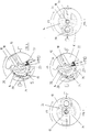
- la figure 1 est une vue schématique d'une commande rotative de disjoncteur équipée du dispositif de sectionnement selon l'invention, la poignée étant représentée en position F de fermeture;
- la figure 2 montre une vue identique partiellement arrachée de la figure 1, lors d'une ouverture manuelle de la poignée en l'absence de soudage des contacts;
- la figure 3 est une vue identique de la figure 1 en position O d'ouverture de la poignée;
- la figure 4 est une vue identique de la figure 2 en position de blocage de la poignée dans une position S intermédiaire suite à un soudage des contacts;
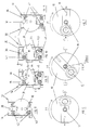
- les figures 5 à 7 représentent une variante de réalisation avec différentes positions de la poignée rotative;
- les figures 8 et 11 montrent l'ensemble came et tiroir respectivement en position de fermeture et d'ouverture, correspondant à la position de la poignée sur les figures 5 et 7;
- les figures 9 et 10 sont des vues identiques de la figure 8 pour la position intermédiaire de la poignée représentée à la figure 6, respectivement en l'absence et en présence d'un soudage des contacts.
- Figure 1 is a schematic view of a rotary circuit breaker control equipped with the disconnecting device according to the invention, the handle being shown in the closed position F;
- FIG. 2 shows an identical view partially cut away from FIG. 1, during a manual opening of the handle in the absence of welding of the contacts;
- Figure 3 is an identical view to Figure 1 in position O of the handle opening;
- Figure 4 is an identical view to Figure 2 in the locking position of the handle in an intermediate position S following welding of the contacts;
- Figures 5 to 7 show an alternative embodiment with different positions of the rotary handle;
- Figures 8 and 11 show the cam and slide assembly respectively in the closed and open position, corresponding to the position of the handle in Figures 5 and 7;
- Figures 9 and 10 are identical views of Figure 8 for the intermediate position of the handle shown in Figure 6, respectively in the absence and in the presence of welding of the contacts.
Sur les figures 1 à 4, une poignée 10 rotative de mécanisme de commande à genouillère d'un disjoncteur électrique à boîtier isolant moulé, est associée à une chaîne cinématique 12 capable de transmettre les mouvements de rotation de la poignée 10 à un barreau de commutation (non représenté) pour l'ouverture et la fermeture manuelle du disjoncteur.In FIGS. 1 to 4, a
Le disjoncteur comporte un mécanisme à genouillère, susceptible d'occuper une position de fermeture des contacts, une position d'ouverture des contacts, et une position intermédiaire de déclenchement ouvert sur défaut.The circuit breaker comprises a toggle mechanism, capable of occupying a position for closing the contacts, a position for opening the contacts, and an intermediate tripping position open on fault.
Pour réaliser le dispositif de sectionnement 13 du disjoncteur, la chaîne cinématique 12 comporte une pièce ou organe de transmission 14 formée par un levier coudé ayant, une première extrémité 16 calée coaxialement sur un arbre 18 rotatif de commande, et une deuxième extrémité 20 entraînée par un bossage 22 de la poignée 10. La zone intermédiaire de la pièce de transmission 14 est dotée d'un ergot 24 de verrouillage susceptible d'occuper une position de repos ou une position de blocage en fonction de l'effort de manoeuvre nécessaire pour faire tourner l'arbre 18 par l'action manuelle de la poignée 10 dans le sens de l'ouverture.To make the circuit breaker disconnecting
La première extrémité 16 de la pièce de transmission 14 est raccordée à la zone intermédiaire par une section rétrécie 26 autorisant une déformation élastique radiale de la pièce 14 en fonction de la valeur du moment du couple de manoeuvre. En position de blocage, l'ergot 24 coopère avec une butée 28 fixe de limitation de la course de la poignée 10. La butée 28 est constituée à titre d'exemple par une nervure circulaire ménagée dans le capot du boîtier isolant moulé.The
Le calibrage de la section rétrécie 26 de la pièce de transmission 14 permet de choisir avec précision le moment du passage de l'ergot 24 de la position de repos vers la position de blocage. En cas de soudage des contacts, la localisation de la butée 28 sur le boîtier permet le blocage de la poignée 10 dans une position S intermédiaire située entre la position PMO de point mort ouverture, et la position O d'ouverture (figure 4).La nervure de la butée 28 présente un rayon légèrement supérieur à celui de l'ergot 24 lorsque ce dernier se trouve en position de repos en cas de non déformation de la pièce de transmission (figure 2).The calibration of the narrowed
Le fonctionnement du mécanisme à dispositif de sectionnement 13 selon les figures 1 à 4 est le suivant:The operation of the disconnecting
Sur la figure 1, la poignée 10 se trouve en position F correspondant à la fermeture des contacts du disjoncteur. L'ouverture manuelle des contacts s'opère par rotation de la poignée 10 dans le sens des aiguilles d'une montre, indiquée par la flèche F1. Le bossage 22 de la poignée 10 entraîne dans le même sens l'arbre 18 de commande par l'intermédiaire de la pièce de transmission 14.In FIG. 1, the
En cas de non soudage des contacts, le moment du couple de manoeuvre est insuffisant pour engendrer la déformation radiale de la pièce de transmission 14. L'ergot 24 reste en position de repos, et glisse le long de la surface cylindrique interne de la nervure de la butée 28 (figure 2) jusqu'à la venue de la poignée 10 en position O d'ouverture (figurai 3). Le cadenassage du disjoncteur peut être opéré dans cette position O d'ouverture grâce à la mise en place d'un cadenas dans la tirette 30 de la poignée 10.In the event of non-welding of the contacts, the moment of the operating torque is insufficient to generate the radial deformation of the
En cas de soudage des contacts de l'un des pôles du disjoncteur, le moment du couple de manoeuvre croît dans le sens d'ouverture de la poignée 10. La déformation radiale de la pièce de transmission 14 intervient lorsque le couple dépasse un seuil prédéterminé, lequel dépend du calibre de la section rétrécie 26. L'ergot 24 de verrouillage est sollicité vers la position de blocage, et vient s'accrocher à la butée 28 lorsque la poignée 10 arrive dans la position S intermédiaire après passage du point mort ouverture PMO, (figure 4). La poignée 10 reste alors immobilisée dans cette position S, et toute tentative de déplacement forcé vers la position O d'ouverture est rendue impossible.In the event of welding of the contacts of one of the poles of the circuit breaker, the moment of the operating torque increases in the direction of opening of the
On remarque que la déformation de la pièce de transmission 14 s'effectue exclusivement en cas de soudage des contacts, et après passage du point mort ouverture PMO suite au déplacement manuel de la poignée 10 dans le sens d'ouverture. Le blocage positif de la poignée 10 dans la position S intermédiaire interdit tout cadenassage, et constitue un indicateur de l'état soudé du disjoncteur.It will be noted that the deformation of the
La pièce de transmission 14 constitue une liaison mécanique élastiquement extensible pouvant être incorporée dans le mécanisme de tout disjoncteur à boîtier isolant moulé avec ou sans bloc de télécommande. La pièce de transmission 14 peut être agencée à n'importe quel endroit de la chaîne cinématique 12 entre la poignée 10 rotative et le barreau de commutation.The
A titre d'exemple, l'arbre 18 rotatif de commande peut faire partie d'un bloc de télécommande adaptable à un disjoncteur à manette pivotante, tel que décrit dans la demande de brevet français 89.14632. L'arbre 18 est accouplé à une came 31 d'entraînement coopérant avec un tiroir de commande 32 (voir figures 5 à 11 suivantes) de la manette pivotante. La poignée 10 rotative est agencée sur la face avant du bloc de télécommande, et sert de commande manuelle de secours.By way of example, the
Selon les figures 1 à 4, on remarque que la pièce de transmission 14 est localisée entre le bossage 22 de la poignée 10 rotative et l'extrémité supérieure de l'arbre 18 de commande, à l'intérieur du bloc de télécommande. En cas de soudage des contacts, la réaction directe de l'ergot 24 sur la butée 28 fixe du boîtier permet de concentrer l'action de blocage au voisinage de la poignée 10.According to Figures 1 to 4, we note that the
Sur la variante des figures 5 à 11, le dispositif de sectionnement 130 est situé dans le bloc de télécommande au niveau du tiroir de commande 32, c'est à dire à l'extrémité inférieure de l'arbre 18 rotatif de la manette pivotante du disjoncteur. La structure élastique du tiroir 32 comporte un premier coulisseau 34 inférieur, ayant une ouverture dans laquelle s'engage la manette pivotante, et un deuxième coulisseau 36 équipé de deux galets 38,40,coopérant avec la came 31 d'entraînement associé à l'arbre 18. Un système de ressorts 42 permet un mouvement relatif de coulissement entre les deux coulisseaux 34,36. La surcourse d (figure 10) résultant de ce mouvement relatif est utilisée pour réaliser le dispositif de sectionnement 130, lequel comprend un pion 44 de verrouillage, solidaire de la came 31 d'entraînement, et un taquet d'arrêt 46 solidaire du premier coulisseau 34 du tiroir 32 élastique.In the variant of FIGS. 5 to 11, the
Le calibrage du système de ressorts 42 détermine la surcourse entre les deux coulisseaux 34,36 en fonction de l'effort de manoeuvre exercé sur le tiroir 32 lors d'une ouverture ou fermeture manuelle par la poignée 10.The calibration of the
Le fonctionnement du mécanisme à dispositif de sectionnement 130 selon les figures 5 à 11 est le suivant:The operation of the disconnecting
En position F de fermeture des contacts, la poignée 10 et l'ensemble came 31 et tiroir 32 élastique de commande se trouvent respectivement dans l'état des figures 5 et 8. L'alignement des deux coulisseaux 34,36 résulte de la présence du système de ressorts 42, évitant toute surcourse dans cette position.In position F of closing of the contacts, the
L'ouverture manuelle du disjoncteur s'opère par rotation d'un demi-tour de la poignée 10 dans le sens de la flèche F1. La came 31 suit le mouvement manuel de la poignée 10, et entraîne le tiroir 32 de commande en translation dans le sens de la flèche F2 (voir figure 9). En l'absence de soudage des contacts, l'effort de manoeuvre est normal et les deux coulisseaux 34,36 du tiroir 32 se déplacent simultanément.Le pion 44 est libre de passer devant le taquet d'arrêt 46 qui se trouve dans une position inactive de repos. La poignée 10 et l'ensemble came 31 et tiroir 32 peuvent alors atteindre la position O d'ouverture représentée sur les figures 7 et 11. Le cadenassage est possible grâce à la tirette 30 de la poignée 10.The manual opening of the circuit breaker is effected by rotation of the
En cas de soudage des contacts d'un pôle,le seuil de calibrage du système de ressorts 42 est dépassé suite à l'effort coissant de manoeuvre. L'apparition de la surcourse d résulte du déplacement du premier coulisseau 34 par rapport au deuxième coulisseau 36 qui reste immobile. Le taquet d'arrêt 46 suit le mouvement du premier coulisseau 34 pendant la surcourse d, de manière à stopper le pion 44 de verrouillage lorsque la came 31 arrive dans la position de la figure 10, correspondant à la position S intermédiaire de la poignée 10 (figure 6). La poignée 10 reste immobilisée dans la position S intermédiaire qui se trouve comme sur les figures 1 à 4, entre le point mort ouverture PMO et la position O d'ouverture.In the event of welding of the contacts of a pole, the calibration threshold of the
Dans les deux modes de réalisation décrits précédemment, la fonction de sectionnement du disjoncteur est reportée dans la partie du mécanisme appartenant au bloc de commande rotative à distance ou manuelle, c'est à dire entre la manette pivotante du disjoncteur, et la poignée 10 rotative.In the two embodiments described above, the sectioning function of the circuit breaker is reported in the part of the mechanism belonging to the rotary remote or manual control unit, that is to say between the pivoting lever of the circuit breaker, and the rotary handle. .
Claims (9)
- An operating mechanism of an electrical circuit breaker equipped with a toggle with dead point passage and with a pair of stationary and movable contacts per pole, and comprising a kinematic chain (12) having an operating handle (10) movable between a closed position (F) and an open position (O) corresponding respectively to the closed state and to the open state of the contacts, and a disconnecting device. (13, 130) enabling, in case of manual opening and welding of the contacts, blocking of the handle (10) in an intermediate position (S) situated between the open dead point position (PMO) and the open position (O), said disconnecting device (13, 130) being provided with a transmission part (14, 31, 44) of the kinematic chain (12) cooperating with a stop (28, 46) limiting the travel of the handle (10) for indication of welding of the contacts in said intermediate position (S),
characterized in that the disconnecting device (13, 130) comprises an elastically extendible mechanical link, which undergoes a deformation when passing from a first rest position to a second blocking position after passing the dead point of the toggle, so as to generate a relative movement between the transmission part (14, 31, 44) and the stop (28, 46) when the operating force exerted on the handle (10) exceeds a preset threshold. - The operating mechanism according to claim 1, characterized in that said elastically extendible mechanical link of the disconnecting device (13, 130) is integrated in the toggle housed in the insulating case of the circuit breaker.
- The operating mechanism according to claim 1, characterized in that said elastically extendible mechanical link of the disconnecting device (13, 130) is arranged in the kinematic chain (12) of a remote or manual control unit which can be fitted onto the circuit breaker case.
- The operating mechanism according to claim 2 or 3, characterized in that the transmission part of the disconnecting device (13) comprises an elbow lever having a first end (16) keyed onto a rotary operating shaft (18), a second end (20) driven by a boss (22) of the rotary handle (10), and a locking spigot (24) fixed to the deformable intermediate zone of the lever, so as to latch onto a fixed stop (28) in the second blocking position.
- The operating mechanism according to claim 4, characterized in that the intermediate zone of the lever is connected to the first end (16) by a reduced section (26) calibrated to enable a permanent deformation in case of welding of the contacts.
- The operating mechanism according to claim 4 or 5, characterized in that the fixed stop (28) limiting the travel of the handle (10) is formed by a circular rib moulded with the case, the rib being centred on the rotary shaft (18) with a radius respectively greater than and smaller than that of the spigot (24) when the latter is in the first rest position, and in the second blocking position.
- The operating mechanism according to claim 3, characterized in that the transmission part of the disconnecting device (130) comprises a locking pin (44) arranged on a cam (31) of a shaft (18) coupled to the rotary handle (10), and that the cam (31) cooperates with a flexible control rack (32), equipped with a stop cleat (46) forming a stop for the locking pin (44) in the second blocking position.
- The operating mechanism according to claim 7, characterized in that the control rack (32) comprises a first slide (34) coupled to the pivoting handle of the circuit breaker and equipped with said stop cleat (46), and a second slide (36) equipped with rollers (38, 40) cooperating with the cam (31), and that a spring system (42) is arranged between the two slides (34, 36) to create an overtravel d when the relative movement takes place to the blocking position.
- The operating mechanism according to claim 8, characterized in that the overtravel d results from sliding of the first slide (34) whereas the second slide (36) remains immobile, and that the stop cleat (46) follows the sliding movement of the first slide (34) to stop the cam (31) by the locking pin (44), when the handle (10) reaches the intermediate position (S).
Applications Claiming Priority (2)
| Application Number | Priority Date | Filing Date | Title |
|---|---|---|---|
| FR9010665 | 1990-08-23 | ||
| FR9010665A FR2666168B1 (en) | 1990-08-23 | 1990-08-23 | CONTROL MECHANISM WITH CIRCUIT BREAKER FOR ELECTRIC CIRCUIT BREAKER. |
Publications (2)
| Publication Number | Publication Date |
|---|---|
| EP0472477A1 EP0472477A1 (en) | 1992-02-26 |
| EP0472477B1 true EP0472477B1 (en) | 1995-09-20 |
Family
ID=9399856
Family Applications (1)
| Application Number | Title | Priority Date | Filing Date |
|---|---|---|---|
| EP19910420274 Expired - Lifetime EP0472477B1 (en) | 1990-08-23 | 1991-07-24 | Actuating mechanism with isolating device for electrical circuit breaker |
Country Status (4)
| Country | Link |
|---|---|
| EP (1) | EP0472477B1 (en) |
| DE (1) | DE69113179T2 (en) |
| ES (1) | ES2079615T3 (en) |
| FR (1) | FR2666168B1 (en) |
Cited By (1)
| Publication number | Priority date | Publication date | Assignee | Title |
|---|---|---|---|---|
| CN1881495B (en) * | 2005-06-14 | 2010-07-28 | 施耐德电器工业公司 | Actuating device for an electrical switch device with rotational locking means |
Families Citing this family (1)
| Publication number | Priority date | Publication date | Assignee | Title |
|---|---|---|---|---|
| CN109378232B (en) * | 2018-11-06 | 2024-01-23 | 安士缔(中国)电气设备有限公司 | Mechanical forced starting device applied to star-delta voltage reduction starting of fire pump |
Family Cites Families (5)
| Publication number | Priority date | Publication date | Assignee | Title |
|---|---|---|---|---|
| US2937254A (en) * | 1957-02-05 | 1960-05-17 | Gen Electric | Panelboard unit |
| FR2378345A1 (en) * | 1977-01-24 | 1978-08-18 | Merlin Gerin | Line protecting circuit breaker with rotary handles - has actuating mechanism transmitting handle turning to toggle during first rotation phase |
| FR2436491A1 (en) * | 1978-09-12 | 1980-04-11 | Merlin Gerin | LOW VOLTAGE MULTIPOLAR ELECTRIC CIRCUIT BREAKER WITH AUXILIARY CONTROL BLOCKS |
| US4399420A (en) * | 1981-09-11 | 1983-08-16 | Square D Company | Main circuit breaker |
| DE3217255C1 (en) * | 1982-05-07 | 1983-06-09 | Siemens AG, 1000 Berlin und 8000 München | Circuit breaker drive device for load interruptor circuit breakers in medium-voltage installations |
-
1990
- 1990-08-23 FR FR9010665A patent/FR2666168B1/en not_active Expired - Fee Related
-
1991
- 1991-07-24 ES ES91420274T patent/ES2079615T3/en not_active Expired - Lifetime
- 1991-07-24 DE DE1991613179 patent/DE69113179T2/en not_active Expired - Fee Related
- 1991-07-24 EP EP19910420274 patent/EP0472477B1/en not_active Expired - Lifetime
Cited By (1)
| Publication number | Priority date | Publication date | Assignee | Title |
|---|---|---|---|---|
| CN1881495B (en) * | 2005-06-14 | 2010-07-28 | 施耐德电器工业公司 | Actuating device for an electrical switch device with rotational locking means |
Also Published As
| Publication number | Publication date |
|---|---|
| DE69113179D1 (en) | 1995-10-26 |
| ES2079615T3 (en) | 1996-01-16 |
| FR2666168B1 (en) | 1992-10-30 |
| EP0472477A1 (en) | 1992-02-26 |
| FR2666168A1 (en) | 1992-02-28 |
| DE69113179T2 (en) | 1996-04-18 |
Similar Documents
| Publication | Publication Date | Title |
|---|---|---|
| EP0224396B1 (en) | Control mechanism for a low-tension electric circuit breaker | |
| EP0612087B1 (en) | Remote controlled circuit breaker with disconnecting function | |
| EP2436020B1 (en) | Catching and locking device inside a switch or circuit breaker | |
| EP1975971B1 (en) | Device for controlling an electric protection device and electric protection device including same | |
| EP0140761A2 (en) | Operating mechanism for a low-voltage multi-pole circuit breaker | |
| FR2631485A1 (en) | MINIATURE CIRCUIT BREAKER CONTROL MECHANISM WITH CONTACT WELDING INDICATOR | |
| EP0633591A1 (en) | Actuating mechanism for electric modular circuit breaker | |
| FR2534412A1 (en) | ELECTRIC SWITCH WITH STOPPING OF CONTROL LEVER IN CASE OF WELDING OF CONTACTS | |
| EP0205361B1 (en) | Hand-actuated snap-closing mechanism for a miniaturized circuit breaker | |
| EP2061058B1 (en) | Device for controlling electrical switchgear and electrical switchgear including same | |
| EP2131378A1 (en) | Device for controlling an electrical cut-off device comprising a device for indicating the weld of the contacts, and electrical cut-off device including such a device | |
| EP0326446B1 (en) | Auxiliary controlling and indicating switch for a modular multipole circuit breaker | |
| EP0161946B1 (en) | Auxiliary module for connection to a circuit breaker | |
| EP0286474B1 (en) | Operating mechanism for a switch with three positions | |
| EP0612092B1 (en) | Circuit breaker with adaptable remote control unit | |
| EP0408466B1 (en) | Operating mechanism for an electric switch | |
| EP0472477B1 (en) | Actuating mechanism with isolating device for electrical circuit breaker | |
| EP3249673A1 (en) | Mechanism for signalling an electrical fault in an electric protection device, and electric protection device including such a mechanism | |
| EP0901142A1 (en) | Device for indicating an electrical fault in a switching device, like a differential circuit breaker | |
| BE897953A (en) | IMPROVED SECTIONABLE ELECTRIC SWITCH | |
| EP0602024B1 (en) | Operating mechanism for a multipolar fault-current protective switch with a rotary crossbar | |
| WO2020002850A1 (en) | Manual control device for a remotely operated source inverter | |
| FR2656155A1 (en) | Adaptation accessory for a multi-pole differential switch | |
| EP2061060B1 (en) | Electrical switchgear such as a circuit breaker or a switch | |
| FR2659791A1 (en) | AUXILIARY SWITCH DEVICE FOR A MANUAL CONTROL MOTOR PROTECTION CIRCUIT BREAKER. |
Legal Events
| Date | Code | Title | Description |
|---|---|---|---|
| PUAI | Public reference made under article 153(3) epc to a published international application that has entered the european phase |
Free format text: ORIGINAL CODE: 0009012 |
|
| AK | Designated contracting states |
Kind code of ref document: A1 Designated state(s): BE CH DE ES GB IT LI SE |
|
| 17P | Request for examination filed |
Effective date: 19920707 |
|
| 17Q | First examination report despatched |
Effective date: 19940426 |
|
| RAP1 | Party data changed (applicant data changed or rights of an application transferred) |
Owner name: SCHNEIDER ELECTRIC SA |
|
| GRAA | (expected) grant |
Free format text: ORIGINAL CODE: 0009210 |
|
| AK | Designated contracting states |
Kind code of ref document: B1 Designated state(s): BE CH DE ES GB IT LI SE |
|
| REF | Corresponds to: |
Ref document number: 69113179 Country of ref document: DE Date of ref document: 19951026 |
|
| ITF | It: translation for a ep patent filed | ||
| GBT | Gb: translation of ep patent filed (gb section 77(6)(a)/1977) |
Effective date: 19951127 |
|
| REG | Reference to a national code |
Ref country code: ES Ref legal event code: FG2A Ref document number: 2079615 Country of ref document: ES Kind code of ref document: T3 |
|
| PLBE | No opposition filed within time limit |
Free format text: ORIGINAL CODE: 0009261 |
|
| STAA | Information on the status of an ep patent application or granted ep patent |
Free format text: STATUS: NO OPPOSITION FILED WITHIN TIME LIMIT |
|
| 26N | No opposition filed | ||
| PGFP | Annual fee paid to national office [announced via postgrant information from national office to epo] |
Ref country code: SE Payment date: 19970716 Year of fee payment: 7 |
|
| PGFP | Annual fee paid to national office [announced via postgrant information from national office to epo] |
Ref country code: ES Payment date: 19970729 Year of fee payment: 7 |
|
| PGFP | Annual fee paid to national office [announced via postgrant information from national office to epo] |
Ref country code: CH Payment date: 19970806 Year of fee payment: 7 |
|
| PGFP | Annual fee paid to national office [announced via postgrant information from national office to epo] |
Ref country code: BE Payment date: 19970911 Year of fee payment: 7 |
|
| PG25 | Lapsed in a contracting state [announced via postgrant information from national office to epo] |
Ref country code: SE Free format text: LAPSE BECAUSE OF NON-PAYMENT OF DUE FEES Effective date: 19980725 Ref country code: ES Free format text: LAPSE BECAUSE OF NON-PAYMENT OF DUE FEES Effective date: 19980725 |
|
| PG25 | Lapsed in a contracting state [announced via postgrant information from national office to epo] |
Ref country code: LI Free format text: LAPSE BECAUSE OF NON-PAYMENT OF DUE FEES Effective date: 19980731 Ref country code: CH Free format text: LAPSE BECAUSE OF NON-PAYMENT OF DUE FEES Effective date: 19980731 Ref country code: BE Free format text: LAPSE BECAUSE OF NON-PAYMENT OF DUE FEES Effective date: 19980731 |
|
| BERE | Be: lapsed |
Owner name: S.A. SCHNEIDER ELECTRIC Effective date: 19980731 |
|
| REG | Reference to a national code |
Ref country code: CH Ref legal event code: PL |
|
| EUG | Se: european patent has lapsed |
Ref document number: 91420274.2 |
|
| PGFP | Annual fee paid to national office [announced via postgrant information from national office to epo] |
Ref country code: DE Payment date: 19990708 Year of fee payment: 9 |
|
| PGFP | Annual fee paid to national office [announced via postgrant information from national office to epo] |
Ref country code: GB Payment date: 19990721 Year of fee payment: 9 |
|
| PG25 | Lapsed in a contracting state [announced via postgrant information from national office to epo] |
Ref country code: GB Free format text: LAPSE BECAUSE OF NON-PAYMENT OF DUE FEES Effective date: 20000724 |
|
| GBPC | Gb: european patent ceased through non-payment of renewal fee |
Effective date: 20000724 |
|
| PG25 | Lapsed in a contracting state [announced via postgrant information from national office to epo] |
Ref country code: DE Free format text: LAPSE BECAUSE OF NON-PAYMENT OF DUE FEES Effective date: 20010501 |
|
| REG | Reference to a national code |
Ref country code: ES Ref legal event code: FD2A Effective date: 19990811 |
|
| PG25 | Lapsed in a contracting state [announced via postgrant information from national office to epo] |
Ref country code: IT Free format text: LAPSE BECAUSE OF NON-PAYMENT OF DUE FEES Effective date: 20050724 |