EP0472403A2 - Mikrowellen-Phasenmodulation mit Flüssigkristallen - Google Patents
Mikrowellen-Phasenmodulation mit Flüssigkristallen Download PDFInfo
- Publication number
- EP0472403A2 EP0472403A2 EP91307659A EP91307659A EP0472403A2 EP 0472403 A2 EP0472403 A2 EP 0472403A2 EP 91307659 A EP91307659 A EP 91307659A EP 91307659 A EP91307659 A EP 91307659A EP 0472403 A2 EP0472403 A2 EP 0472403A2
- Authority
- EP
- European Patent Office
- Prior art keywords
- liquid crystal
- microwave
- cell
- phase modulating
- alignment
- Prior art date
- Legal status (The legal status is an assumption and is not a legal conclusion. Google has not performed a legal analysis and makes no representation as to the accuracy of the status listed.)
- Withdrawn
Links
- 239000004973 liquid crystal related substance Substances 0.000 title claims abstract description 166
- 230000005291 magnetic effect Effects 0.000 claims abstract description 22
- 239000000463 material Substances 0.000 claims description 29
- 230000005684 electric field Effects 0.000 claims description 24
- 238000000034 method Methods 0.000 claims description 16
- ZUOUZKKEUPVFJK-UHFFFAOYSA-N diphenyl Chemical compound C1=CC=CC=C1C1=CC=CC=C1 ZUOUZKKEUPVFJK-UHFFFAOYSA-N 0.000 claims description 6
- 229920000642 polymer Polymers 0.000 claims description 6
- JRXXLCKWQFKACW-UHFFFAOYSA-N biphenylacetylene Chemical compound C1=CC=CC=C1C#CC1=CC=CC=C1 JRXXLCKWQFKACW-UHFFFAOYSA-N 0.000 claims description 4
- -1 biphenylpyrimidine Chemical compound 0.000 claims description 4
- YJTKZCDBKVTVBY-UHFFFAOYSA-N 1,3-Diphenylbenzene Chemical group C1=CC=CC=C1C1=CC=CC(C=2C=CC=CC=2)=C1 YJTKZCDBKVTVBY-UHFFFAOYSA-N 0.000 claims description 3
- HMQFJYLWNWIYKQ-UHFFFAOYSA-N 1,4-diphenylbutadiyne Chemical group C1=CC=CC=C1C#CC#CC1=CC=CC=C1 HMQFJYLWNWIYKQ-UHFFFAOYSA-N 0.000 claims description 3
- 239000002262 Schiff base Substances 0.000 claims description 3
- 150000004753 Schiff bases Chemical class 0.000 claims description 3
- 235000010290 biphenyl Nutrition 0.000 claims description 3
- 239000004305 biphenyl Substances 0.000 claims description 3
- 230000003098 cholesteric effect Effects 0.000 claims description 3
- CGLGVKOSEKPHBD-UHFFFAOYSA-N 1-[[2-(hydroxymethyl)phenyl]methyl]pyrimidine-2,4-dione Chemical compound OCC1=CC=CC=C1CN1C(=O)NC(=O)C=C1 CGLGVKOSEKPHBD-UHFFFAOYSA-N 0.000 claims description 2
- 239000004990 Smectic liquid crystal Substances 0.000 claims description 2
- 125000003118 aryl group Chemical group 0.000 claims description 2
- 230000001939 inductive effect Effects 0.000 claims 1
- 238000003491 array Methods 0.000 abstract description 5
- 239000004983 Polymer Dispersed Liquid Crystal Substances 0.000 description 20
- 230000010363 phase shift Effects 0.000 description 13
- 230000010287 polarization Effects 0.000 description 8
- 230000004044 response Effects 0.000 description 7
- 230000000694 effects Effects 0.000 description 6
- 239000007788 liquid Substances 0.000 description 6
- 239000000203 mixture Substances 0.000 description 6
- 239000007787 solid Substances 0.000 description 6
- 239000004988 Nematic liquid crystal Substances 0.000 description 5
- 238000013459 approach Methods 0.000 description 5
- 230000003287 optical effect Effects 0.000 description 5
- 230000005374 Kerr effect Effects 0.000 description 4
- 238000013019 agitation Methods 0.000 description 4
- 230000008901 benefit Effects 0.000 description 4
- 230000008859 change Effects 0.000 description 4
- 239000013078 crystal Substances 0.000 description 4
- 230000005292 diamagnetic effect Effects 0.000 description 4
- 239000011521 glass Substances 0.000 description 4
- 239000004033 plastic Substances 0.000 description 4
- 229920003023 plastic Polymers 0.000 description 4
- 229910000859 α-Fe Inorganic materials 0.000 description 4
- 230000007423 decrease Effects 0.000 description 3
- 239000012530 fluid Substances 0.000 description 3
- FEIWNULTQYHCDN-UHFFFAOYSA-N mbba Chemical compound C1=CC(CCCC)=CC=C1N=CC1=CC=C(OC)C=C1 FEIWNULTQYHCDN-UHFFFAOYSA-N 0.000 description 3
- 238000005259 measurement Methods 0.000 description 3
- 229910052751 metal Inorganic materials 0.000 description 3
- 239000002184 metal Substances 0.000 description 3
- 239000002245 particle Substances 0.000 description 3
- 238000005191 phase separation Methods 0.000 description 3
- 238000001228 spectrum Methods 0.000 description 3
- 239000000126 substance Substances 0.000 description 3
- 239000000725 suspension Substances 0.000 description 3
- 229910021532 Calcite Inorganic materials 0.000 description 2
- 238000010521 absorption reaction Methods 0.000 description 2
- 230000003213 activating effect Effects 0.000 description 2
- 239000011324 bead Substances 0.000 description 2
- 239000011248 coating agent Substances 0.000 description 2
- 238000000576 coating method Methods 0.000 description 2
- 230000002349 favourable effect Effects 0.000 description 2
- 230000007246 mechanism Effects 0.000 description 2
- 239000012188 paraffin wax Substances 0.000 description 2
- 239000000843 powder Substances 0.000 description 2
- 238000012360 testing method Methods 0.000 description 2
- 238000004804 winding Methods 0.000 description 2
- GSRYYYQXHBANQW-UHFFFAOYSA-N (4-butylphenyl) 4-methylbenzoate Chemical compound C1=CC(CCCC)=CC=C1OC(=O)C1=CC=C(C)C=C1 GSRYYYQXHBANQW-UHFFFAOYSA-N 0.000 description 1
- XQRFASOUJIKXRE-UHFFFAOYSA-N (4-cyanophenyl) 4-butylbenzoate Chemical compound C1=CC(CCCC)=CC=C1C(=O)OC1=CC=C(C#N)C=C1 XQRFASOUJIKXRE-UHFFFAOYSA-N 0.000 description 1
- ZWAUTNYPKHVAEZ-UHFFFAOYSA-N (4-cyanophenyl) 4-heptylbenzoate Chemical compound C1=CC(CCCCCCC)=CC=C1C(=O)OC1=CC=C(C#N)C=C1 ZWAUTNYPKHVAEZ-UHFFFAOYSA-N 0.000 description 1
- OXPDQFOKSZYEMJ-UHFFFAOYSA-N 2-phenylpyrimidine Chemical compound C1=CC=CC=C1C1=NC=CC=N1 OXPDQFOKSZYEMJ-UHFFFAOYSA-N 0.000 description 1
- ZGOWXOZNUNZPAV-UHFFFAOYSA-N 4-(4-heptylphenyl)benzonitrile Chemical group C1=CC(CCCCCCC)=CC=C1C1=CC=C(C#N)C=C1 ZGOWXOZNUNZPAV-UHFFFAOYSA-N 0.000 description 1
- CSQPODPWWMOTIY-UHFFFAOYSA-N 4-(4-octylphenyl)benzonitrile Chemical group C1=CC(CCCCCCCC)=CC=C1C1=CC=C(C#N)C=C1 CSQPODPWWMOTIY-UHFFFAOYSA-N 0.000 description 1
- 239000005253 4-Cyano-4'-heptylbiphenyl Substances 0.000 description 1
- 239000005212 4-Cyano-4'-pentylbiphenyl Substances 0.000 description 1
- 239000005194 4-Cyanophenyl 4-Heptylbenzoate Substances 0.000 description 1
- HHPCNRKYVYWYAU-UHFFFAOYSA-N 4-cyano-4'-pentylbiphenyl Chemical group C1=CC(CCCCC)=CC=C1C1=CC=C(C#N)C=C1 HHPCNRKYVYWYAU-UHFFFAOYSA-N 0.000 description 1
- 229920002799 BoPET Polymers 0.000 description 1
- 239000005041 Mylar™ Substances 0.000 description 1
- 239000004372 Polyvinyl alcohol Substances 0.000 description 1
- ACAXIUADIABHTE-UHFFFAOYSA-N [4-(4-butylphenoxy)carbonylphenyl] 4-butylbenzoate Chemical compound C1=CC(CCCC)=CC=C1OC(=O)C(C=C1)=CC=C1OC(=O)C1=CC=C(CCCC)C=C1 ACAXIUADIABHTE-UHFFFAOYSA-N 0.000 description 1
- 239000000853 adhesive Substances 0.000 description 1
- 230000001070 adhesive effect Effects 0.000 description 1
- 229910052782 aluminium Inorganic materials 0.000 description 1
- XAGFODPZIPBFFR-UHFFFAOYSA-N aluminium Chemical compound [Al] XAGFODPZIPBFFR-UHFFFAOYSA-N 0.000 description 1
- 238000009529 body temperature measurement Methods 0.000 description 1
- 239000004568 cement Substances 0.000 description 1
- 239000000084 colloidal system Substances 0.000 description 1
- 238000001816 cooling Methods 0.000 description 1
- 230000003247 decreasing effect Effects 0.000 description 1
- 238000013461 design Methods 0.000 description 1
- 238000011161 development Methods 0.000 description 1
- 239000006185 dispersion Substances 0.000 description 1
- 238000006073 displacement reaction Methods 0.000 description 1
- 230000009977 dual effect Effects 0.000 description 1
- 230000005672 electromagnetic field Effects 0.000 description 1
- 150000002148 esters Chemical class 0.000 description 1
- 239000004744 fabric Substances 0.000 description 1
- 238000005189 flocculation Methods 0.000 description 1
- 230000016615 flocculation Effects 0.000 description 1
- 230000009969 flowable effect Effects 0.000 description 1
- 230000005484 gravity Effects 0.000 description 1
- 238000010438 heat treatment Methods 0.000 description 1
- 239000012456 homogeneous solution Substances 0.000 description 1
- 230000006872 improvement Effects 0.000 description 1
- 239000012784 inorganic fiber Substances 0.000 description 1
- 230000000670 limiting effect Effects 0.000 description 1
- 230000033001 locomotion Effects 0.000 description 1
- 238000004519 manufacturing process Methods 0.000 description 1
- 239000002923 metal particle Substances 0.000 description 1
- 239000013528 metallic particle Substances 0.000 description 1
- 238000012986 modification Methods 0.000 description 1
- 230000004048 modification Effects 0.000 description 1
- 230000036961 partial effect Effects 0.000 description 1
- 230000000704 physical effect Effects 0.000 description 1
- 229920006267 polyester film Polymers 0.000 description 1
- 229920002451 polyvinyl alcohol Polymers 0.000 description 1
- 239000005373 porous glass Substances 0.000 description 1
- 230000001902 propagating effect Effects 0.000 description 1
- 230000005855 radiation Effects 0.000 description 1
- 230000002829 reductive effect Effects 0.000 description 1
- 230000002441 reversible effect Effects 0.000 description 1
- 238000012552 review Methods 0.000 description 1
- 239000000758 substrate Substances 0.000 description 1
- 238000010408 sweeping Methods 0.000 description 1
- 230000007704 transition Effects 0.000 description 1
- 238000001429 visible spectrum Methods 0.000 description 1
Images



Classifications
-
- H—ELECTRICITY
- H03—ELECTRONIC CIRCUITRY
- H03C—MODULATION
- H03C7/00—Modulating electromagnetic waves
- H03C7/02—Modulating electromagnetic waves in transmission lines, waveguides, cavity resonators or radiation fields of antennas
Definitions
- the index of refraction of some birefringent materials and of Kerr-effect isotropic materials can be controllably varied directionally by the application of a magnetic or electrical field to the medium.
- liquid crystals are known to be birefringent for visible light, and variable under the application of an electric field. This property has been used in liquid crystal light valves to make color projection displays.
- Liquid crystals have been known for more than 100 years, with particularly extensive development of new materials and devices in the last 30 years.
- the following references provide a general background to the structures, classifications, nomenclature, and applications of liquid crystals: "Liquid Crystals", Proc. of Inter. Liquid Crystal Conf., Bangalore, India, Ed. by S. Chandrasekhar (Bangalore Book Printers, 1973); G.H. Brown et al., "A Review of the Structure and Physical Properties of Liquid Crystals, Ed. by B.J. Starkoff (The Chemical Rubber Company by CRC Press, 1971); “Liquid Crystals, The Fourth State of Matter”, Ed. by F.D. Saeva (Marcel Decker, 1979); G.W.
- Birefringent materials have been known and used for controlling visible light, and there are many potential applications for such materials in other portions of the electromagnetic spectrum such as the microwave range. Although viable birefringent and Kerr-effect materials are known for use in the visible-light frequency range, until recent years there have been known few if any practical Kerr-effect materials nor any birefringent materials for microwave radiation applications. The most promising reported Kerr-effect materials for use in the microwave range are suspensions of highly asymmetric metallic particles in organic liquids. It is, however, difficult to maintain a stable suspension of the high concentration of particles required for practical applications. Mechanical agitation (by circulation of the fluid) has been used in the microwave studies of these Kerr media, but continuous mechanical agitation is not practical for many device applications. The birefringence of these suspensions, when achieved, is typically about 0.08 or less.
- the present invention provides a birefringent medium that is relatively stable against changes in the medium during use, such as phase separation between the particles and the suspending fluid.
- the medium is useful in a phase modulating cell, which in turn is useful in a phase modulating array.
- the medium of the invention has a high birefringence that can be controlled with applied fields, is inexpensive to fabricate, can be operated with low power consumption, and does not require complex control mechanisms and software for operation.
- a microwave phase modulating cell comprises a microwave wave guide; a phase modulating medium disposed within the wave guide, the phase modulating medium comprising a liquid crystal; and means for controllably aligning the average direction of the liquid crystal molecules in the phase modulating medium.
- a key to the invention is'the discovery that a substantially homogeneous phase modulating medium, a liquid crystal, exhibits a large microwave birefringence which can be utilized by orientation of the liquid crystal with applied electric and magnetic fields.
- the visible light birefringence of liquid crystals which is associated with their anisotropic molecular polarizabilities, and related to electronic band transitions in the ultraviolet region (above about 1015 Hz), is well known. This birefringence extends into the infrared region, where it is also affected by anisotropy of vibrational molecular motions.
- the present invention therefore represents an important advance in the art of microwave devices.
- Microwave range liquid crystal phase modulators that operate at low power, are compact in size, have low fabrication cost, and can be assembled in large arrays may be fabricated.
- the liquid crystals are macroscopically homogeneous, and do not exhibit the flocculation and/or gravity-driven phase separation observed in those microwave phase modulators which are a mixture of particles and a carrier phase.
- the present invention is based upon the use of thermotropic types of liquid crystals (including nematic, cholesteric or chiral, and smectic phases) which can be aligned by applied electrical and/or magnetic fields, and which have birefringent properties in the microwave (including millimeter wave) electromagnetic range.
- Microwave modulators and devices can be made with a wide range of such liquid crystal structures, which have surprisingly high birefringent values along with acceptably low dielectric loss values in the microwave region.
- the liquid crystals are stable fluids, and do not require the constant agitation of the previously known metal particle/organic liquid microwave birefringent materials.
- liquid crystal structures for achieving microwave birefringence are highly conjugated, rod-like, type molecular structures, such as for example structures containing biphenyl, terphenyl, phenypyrimidine, biphenylpyrimidine, tolane, and diphenyldiacetylene groups.
- Other types of liquid crystal structures, including Schiff bases, azoxybenzenes, and aromatic esters also have substantial birefringence in the microwave region.
- microwave includes electromagnetic waves having wavelengths of from about 1 GHz to about 100 GHz.
- microwave is intended to include the portions of the electromagnetic spectrum that are otherwise sometimes described by the terms microwave and millimeter wave.
- a basic phase modulating cell 20 is depicted in Figure 1.
- the cell 20 includes a microwave wave guide 22, which is a hollow metal tube, usually rectangular in cross section, that is dimensioned for the propagation of microwaves therein.
- a microwave wave guide 22 is a hollow metal tube, usually rectangular in cross section, that is dimensioned for the propagation of microwaves therein.
- dimensions are indicated on the drawing for a cell 20 to be used in conjunction with microwaves having a frequency of 30 GHz in the K a radar band.
- the height A is about 0.35 centimeters
- the width B is about 0.7 centimeters
- the length C is about 10 centimeters.
- the wave guide 22 normally has a mounting flange 24 on each end thereof.
- An interior cavity 26 of the wave guide 22 is filled with a liquid crystal material. The ends of the cavity 26 are closed with thin plastic windows 28 about 15 micrometers thick.
- Apertures are cut into two opposing faces 30 of the rectangular wave guide 22, and opposing electrodes 32 are mounted therein as the means to controllably align the liquid crystal molecules.
- the electrodes 32 are connected to a voltage source V1 so that, when the voltage V1 is applied there is an electric field whose vector extends between the electrodes and transverse to a wave path 34.
- the molecules of the liquid crystal are initially locally aligned in randomly oriented domains.
- the voltage V1 is applied across the electrodes 32, the molecules of a positive dielectric anisotropy liquid crystal align parallel to the field vector and thence perpendicular to the wave path 34. This condition of alignment may be viewed as a first aligned state, to be distinguished from the randomly oriented state.
- a second means for aligning the molecules of the liquid crystal is provided.
- the second means could be another set of electrodes similar to the electrodes 32, except oriented with the field vector between the electrodes at a different angle to the wave path 34.
- magnet pole pieces are mounted on opposing sides of the cavity 26 such that the line between the pole pieces is at some other angle to the wave path 34.
- These magnets can be permanent magnets, in which case the orthogonal electric field, when applied, must have sufficient strength to overcome the magnetic field.
- apertures are cut into the other two opposing faces 36 and a pair of opposing electromagnet pole pieces 38 mounted in the apertures. The windings of the pole pieces 38 are connected to a second voltage source V2.
- two sets of orthogonal electrodes could be used, although control of the orientation of the liquid crystal using two separate types of forces may reduce the field between the electrodes set at right angles to each other.
- a method for modulating the phase of a microwave comprises the steps of providing a microwave phase modulating cell comprising a phase modulating medium, the phase modulating medium comprising a liquid crystal, and means for controlling the alignment of the liquid crystal; directing a beam of microwave energy through the cell in a microwave propagation direction; and operating the means for controllably aligning the liquid crystal, thereby changing the microwave index of refraction of the phase modulating medium.
- a polarized microwave beam having an electric field vector P is directed through the wave guide 22 parallel to its axis along the wave path 34, and through the windows 28.
- the index of refraction of the birefringent medium within the wave guide 22, relative to the microwave beam, is controlled by adjusting the voltages V1 and V2.
- voltage V2 to the electromagnets 38 is maintained zero and the voltage V1 to the electrodes 32 is increased to align the molecules of the positive dielectric anisotropy liquid crystal perpendicular to the faces 30.
- V1 is reduced to zero and V2 is gradually increased to align molecules of the liquid crystal perpendicular to the faces 36.
- the velocity of the microwave is altered as the voltages are changed, and the index of refraction of the medium within the phase modulating cell is also altered.
- phase modulating cells like that of Figure 1 were constructed to evaluate the approach of the invention.
- the liquid crystal was placed into each of the phase modulating cells.
- the microwave wave had a frequency of 30 GHz, so standard WR-28 wave guides were used.
- Phase shift modulations of three types were observed with these cells, specifically (a) from random liquid crystal alignment to electrical field (E-field) alignment, (b) from random alignment to magnetic field (H-field) alignment, and (c) from E-field alignment (without H-field) to orthogonal H-field alignment (without E-field).
- E-field electrical field
- H-field magnetic field
- E-field alignment without H-field
- a voltage of 300 Volts at 60 Hz was applied between the electrodes 32, which were spaced 0.35 centimeters apart, and a magnetic field of 3 kilogauss was applied.
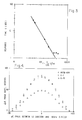
- Figure 2 depicts the phase shift of the microwave as a function of the path length, that is, the length of microwave travel through the liquid crystal, as the liquid crystal orientation was changed from E-field alignment to the orthogonal H-field alignment.
- ROTN-404 and BDH-E7 liquid crystal compositions are commercially available from Hoffman-LaRoche and BDH Chemical, Ltd., respectively.
- the birefringence of the liquid crystal is defined as the difference between its refractive index parallel to the director of the liquid crystal and its refractive index perpendicular to the director of the liquid crystal.
- liquid crystal birefringence in the microwave region is surprising and unexpected, and has not been previously reported.
- liquid crystals exhibit birefringence in the visible spectrum, the observed birefringence decreases from the ultraviolet (3 x 10 ⁇ 5 centimeter wavelength) through the visible and into the infrared (10 ⁇ 3 centimeter wavelength) regions, while the microwave region has a much longer wavelength of about 0.3 to 30 centimeters.
- liquids generally exhibit strong dispersion in many of their dielectric, absorption loss, and relaxation properties in going from the visible to the microwave region, as described by P. Debye, "Polar Molecules", Chemical Catalog Co., Chapter V (New York, 1929).
- the dielectric anisotropy of liquid crystals is known to exhibit somewhat unpredictable behavior in the 1 kHz to 100 MHz range, and may decrease and remain positive, become zero, or decrease and become negative in that range.
- the response time to achieve the first aligned state was measured for the BDH-E7 material, as a function of the voltage applied to the electrodes 32, and the results are shown in Figure 3.
- the shortest response time in the cell of Figure 1 was about 1.5 seconds for applied voltages of above 300 volts (850 volts per centimeter), which is a relatively low field strength compared to those used in optical liquid crystal devices, typically more than 10,000 volts per centimeter.
- a variation of the cell of Figure 1 was constructed in which the E-field and the H-field were applied (consecutively) in the same direction, both parallel to the polarization direction of the 30 GHz microwave signal.
- the cell was filled with NP5, a nematic liquid crystal that has a negative dielectric anisotropy and a positive diamagnetic anisotropy, which is commercially available from E. Merck.
- the phase shift difference between these two fields indicated an effective birefringence of 0.09 in this mode of operation.
- Table I presents the calculated microwave birefringences at 30 GHz for the three liquid crystals of Figure 4, and for several other liquid crystals measured in the same manner. Table I also indicates the types of molecular structures present in each of these liquid crystals, most of which are multicomponent mixtures, and for comparison shows their optical birefringence at the visible sodium-D line, 589 nanometers. In most cases, the type of liquid crystal is known and indicated in the table, and this information is sufficient to classify the behavior of the liquid crystal type. The specific compositions are in many cases proprietary to the manufacturers but in some cases are known.
- BDH E7 contains 51 percent 4-cyano-4′-pentylbiphenyl, 25 percent 4-cyano-4′heptylbiphenyl, 16 percent 4-cyano-4′-octylbiphenyl, and 8 percent 4-cyano-4 ⁇ -pentyl-p-terphenyl.
- Hughes NP55 contains 18.8 percent 4-cyanophenyl 4-butylbenzoate, 43.8 percent 4-cyanophenyl 4- heptylbenzoate, 20.8 percent 4-butylphenyl 4-methylbenzoate, and 16.7 percent 4-butylphenyl 4-(4-butylbenzoyloxy)benzoate.
- MBBA is p-methoxybenzylidene p-butylaniline
- NP5 has a negative dielectric anisotropy
- the liquid crystal structures have surprisingly high birefringent values at 30 GHz, up to about 71 percent of their birefringence in the visible range at 589 nanometers. From these comparisons, it has been determined that the most favorable such liquid crystal structures to attain large microwave birefringence are highly conjugated, rod-like, type molecular structures, such as structures containing biphenyl, terphenyl, phenylpyrimidine, biphenylpyrimidine, tolane, and diphenyldiacetylene groups. Many other types of liquid crystal structures, including Schiff bases, azoxybenzenes, and esters also have substantial birefringence in the microwave region.
- Table I includes many different types of liquid crystal structural components, and also various classes of liquid crystals including nematic (ROTN-404, Tolane I/II, E7, NP5, MBBA, K15, and NP-55), a crossover nematic (1085, which at room temperature has a positive dielectric anisotropy at applied voltage frequencies below 3.5 kHz and a negative dielectric anisotropy above 3.5 kHz), and a chiral nematic type of cholesteric (16963). All of the liquid crystal materials in Table I have positive diamagnetic anisotropy, and tend to align in the direction of the applied magnetic field.
- nematic ROTN-404, Tolane I/II, E7, NP5, MBBA, K15, and NP-55
- crossover nematic 1085, which at room temperature has a positive dielectric anisotropy at applied voltage frequencies below 3.5 kHz and a negative dielectric anisotropy above 3.5 kHz
- liquid crystals can be used to achieve other design features. For example, switching between two aligned states can be achieved with a single pair of opposed electrodes. That is, no second pair of electrodes or pole pieces is required.
- Some liquid crystals such as 1085 exhibit a crossover in dielectric anisotropy with frequency of the applied field.
- Crossover nematic liquid crystals have a positive dielectric anisotropy in low frequency applied fields, and negative dielectric anisotropy in high frequency applied fields.
- a number of such crossover liquid crystal mixtures are known, including ZLI-1085 (Table I), ZLI-2976, ROTN 3421, and HRL 2PN6.
- ZLI-1085 and ZLI-2976 are commercially available from E. Merck.
- the ROTN-3421 is commercially available from Hoffman-LaRoche.
- the HRL-2PN6 is a 1:1 mixture of the two liquid crystals EK-11650 and EK-15320 available from Eastman Kodak.
- the room temperature dielectric anisotropy is positive for low frequency electrical fields below their respective crossover frequencies applied to the electrodes 32.
- the room temperature dielectric anisotropy is negative at frequencies above their respective crossover frequencies.
- the orientation of ZLI-1085 from Table I can be switched from parallel to perpendicular to the microwave field vector P by switching the frequency of the voltage applied on electrodes 32 from 100 Hz to 10 kHz, providing a fast response in switching orientation.
- the microwave birefringent phase shift of liquid crystals was also measured over a range of frequencies from 15 to 75 GHz, using a HP8510 vector network analyzer, with external H-field alignment of the liquid crystals.
- Table II for the liquid crystals BDH-E7 and ROTN-404:
- ⁇ ⁇ /cm is the phase shift change per centimeter of path length of liquid crystal in switching an external magnetic field of 3 kilogauss from perpendicular to parallel with respect to the microwave polarization direction.
- the value of ⁇ n is an approximate, calculated value.
- Each of these liquid crystals shows only slightly different values of ⁇ n over a wide range of microwave frequencies. In the same apparatus values of the microwave absorption loss of these liquid crystals were measured and estimated to be no more than about 0.25 to 2 db/cm (decibels per centimeter).
- the relaxation time of a bulk liquid crystal from a, field-aligned state back to its equilibrium state is very slow in the absence of restoring forces such as another field, agitation, flow, or some appreciable surface alignment effects.
- the liquid crystal may require more than 10 hours to relax from an aligned state to a random state.
- the relaxation time may be greatly shortened by including additional surfaces which are in contact with the liquid crystal and provide effective realignment forces. Such surfaces can be obtained by the addition of inert bulk materials such as glass or plastic beads or powders, organic or inorganic fibers, and the like to the liquid crystal.
- Other techniques include the use of porous media such as porous glass or plastic, cloth, felt or the like to contain the liquid crystal within the waveguide, the use of multiple planar surfaces such as parallel conductive electrodes or thin layers of glass or plastic within the waveguide to contain the liquid crystal, or the use of liquid crystals within a microencapsulated system such as microencapsulated powders, encapsualted droplets in a polymer, or a polymer dispersed liquid crystal.
- the use of these surface techniques to speed up the relaxation time may also reduce the effectiveness of the microwave modulation by decreasing the percentage of liquid crystal in a given volume, by aligning some of the liquid crystal in the same direction as the applied field, or by creating surface forces that are too strong to be overcome with the applied fields available.
- E7 polymer was incorporated into a polymer dispersed liquid crystal (PDLC) prepared by ultraviolet curing of a solution of 55 percent BDH-E7 in Norland-NOA65 optical cement to form a solid PDLC block 2.2 centimeters long and of cross sectional size to fit the 30 GHz waveguide.
- PDLC polymer dispersed liquid crystal
- Electrodes were attached directly to the PDLC solid and it was slipped into a waveguide cell of the type shown in Figure 1, except that the waveguide wall was cut away in the area of the electrodes.
- Table III presents results obtained with both techniques, while Figure 5 presents further results obtained with the PDLC material having a modulated optical length of 2.2 centimeters, for E-fields applied between electrodes spaced 0.35 centimeters apart. As shown in Table III, both techniques drastically reduce the relaxation decay time to return to the random state.
- the phase shift change at 30 GHz as a function of an applied electrical field on the PDLC material is shown in Figure 5.
- the E-field induced phase shift of the PDLC sample of Table III and Figure 5 is relatively small with respect to the total volume of the E7 of 55 percent used in the solution from which the PDLC was formed, indicating that most of the liquid crystal droplets in this particular sample were too small to be aligned by the fields which were applied and that only the larger droplets responded to the field.
- Results from the PDLC example of Table III and Figure 5 indicate the basic feasibility of microwave modulation with a solid PDLC material, which can be used to speed up the relaxation response time of field-aligned liquid crystals and which also provides self-containment of the liquid crystal to prevent flow or leakage effects.
- Improved modulation of microwaves with PDLC materials can be obtained by using polymers with low microwave loss containing a high concentration of high resistivity liquid crystal droplets of intermediate sizes, for example in the 5-50 micrometer diameter range.
- a PDLC solid with a low loss polymer may be made by heating a paraffin wax and a liquid crystal, as for example 50 percent by volume of BDH-E7 or BDH-E44, until a homogeneous solution is obtained and then cooling the solution so that the liquid crystal separates out within the paraffin block as droplets or channels.
- a preferred form of a cell 50 using a polymer dispersed liquid crystal microwave phase modulating medium 52 is illustrated in disassembled form in Figure 6.
- the medium 52 is a free-standing piece of the polymer dispersed liquid crystal material such as that disclosed previously or in the '900 patent.
- the ends 54 through which the microwave waves enter and leave the medium 52 are angled.
- Two oppositely disposed electrode plates 56 are attached directly to the lateral sides of the medium 52, such that the electric field vector is perpendicular to the wave path 58.
- the electrode plates 56 function in precisely the same manner as the electrodes 32 discussed previously.
- a second set of electrode plates, or magnetic pole pieces may be provided on the other oppositely disposed lateral faces.
- the entire medium 52 is assembled, and slid lengthwise into a cavity 60 of a conventional length of a microwave wave guide 62 to form the cell 50.
- the wave guide is available commercially and is generally as described previously.
- This cell 50 is then bolted into a longer waveguide or used as a component of an array, or as otherwise might be needed.
- the medium 52 may also be readily used without a separate wave guide, as, for example, part of a large array of separately controllable media in an antenna or other device.
- the field strength in the liquid crystal transverse to the wave path in volts per unit length is an important factor in determining response time of the microwave phase modulating cell. Even for fairly small microwave wave guides of less than one centimeter internal size, the applied voltage must be quite high to attain a large field strength.
- FIG. 7 An approach to increasing the field strength and reducing the response time is illustrated in Figure 7.
- a plurality of pairs of opposing electrodes 70 are provided as part of a medium 72.
- the electrodes 70 are arranged as a series of plates in an interdigitated form, with alternating plates being oppositely charged relative to some intermediate value by connection to a voltage source V3.
- the electrodes are preferably prepared on thin dielectric substrates such as glass or polyester films, covered with a conductive metal coating such as aluminum.
- the electrodes 70 are spaced closely together. Even with a modest applied voltage V3 that is readily produced with an inexpensive power supply, the electric field strength of the field between the electrodes is very large due to the small denominator in the definition of field strength, volts divided by electrode spacing.
- a thin layer 74 of liquid crystal is sandwiched between each pair of electrodes 70, to complete the medium 72.
- the liquid crystal material can be in unconstrained liquid form, or in an encapsulated form such as a polymer dispersed liquid crystal. In the former case, the edges of the medium 72 may be sealed with a polymer adhesive to prevent loss of liquid crystal, or the entire medium 72 may be placed inside a wave guide that is in turn sealed.
- the spacing of the electrodes in the apparatus of Figure 7 depends upon the type of liquid crystal material being activated. For example, with an electrode spacing of 0.5 millimeter, a PDLC medium containing 5-10 micrometer liquid crystal droplets that is formed between the electrodes could be fully field aligned with a field of about 4-10 kilovolts per centimeter in about 10-100 milliseconds and have a relaxation decay time of about 25-250 milliseconds at room temperature.
- nematic liquid crystals can be activated with relatively low voltages of about 25-50 volts, and the surface alignment forces can provide relatively fast decay times, so that both the E-field on-time and the decay time for the E-field off are in the range of about 100-500 milliseconds, depending upon the liquid crystal material.
- the surface alignment used for liquid crystals of positive dielectric anisotropy is a uniform surface-parallel direction, obtained for example by well known methods, such as directionally rubbing an extremely thin coating of polyvinyl alcohol on the electrode. In such a cell, the off-state and on-states have orthogonal liquid crystal alignment directions, providing the maximum phase shift available from the birefringence of the liquid crystal which is held between the electrodes by capillary attraction.
- FIGS 8 and 9 illustrate a travelling wave tunable slot array antenna 80 having a wave guide 82 with a microwave birefringent liquid crystal medium 84 therein, whose effective refractive index can be varied by application of an electric or magnetic field. There are lateral openings 86 in the sides of the wave guide 82. Slot array antennas are well known. An example of a tunable antenna made with a non-birefringent ferrite material is disclosed in US Patent 4,613,869, which disclosure is incorporated by reference.
- the less expensive birefringent liquid crystal medium 84 of the invention is used.
- the openings 86 in the wave guide 82 are sealed with Mylar or a similar window material, or the liquid crystal is furnished in an encapsulated form such as the polymer dispersed liquid crystal discussed previously.
- Electrodes 88 are placed in apertures on the sides of the wave guide 80, as shown in Figure 9. An orthogonal magnetic field can be applied externally.
- the application of a voltage to the electrodes 88 causes the orientation of the molecules in the liquid crystal, which in turn interacts with the microwave to modify its wavelength in the wave guide lg.
- the angle A that satisfies the relation changes, thereby permitting the direction of the antenna to be changed by controlling the voltage applied to the electrodes 88.
- Figure 10 presents experimental results at 30 GHz with a tunable liquid crystal slot array microwave antenna like that illustrated in Figure 8.
- the antenna was constructed of an 18 centimeter long 30 GHz waveguide having 20 slot openings with 0.7 centimeter center-to-center spacing, and was filled with BDH-E7 liquid crystal.
- a microwave beam was emitted at about -1 degree from the perpendicular to the side of the tunable array.
- a 1 kilogauss transverse magnetic field was applied (data shown as squares with solid connecting curve)
- the array emitted a beam that was reversibly shifted to +3 degrees off perpendicular, corresponding to partial alignment of the liquid crystal.
- the slot array antenna was also used in a similar manner as a receiving antenna, and showed greater than 4 degrees difference between the receiving intensity peak angles. This dual functionality is an important advantage in device applications, in contrast to ferrite tunable slot array antennas which cannot be operated in both sending and receiving modes.
- Figures 11 and 12 illustrate an array of microwave phase modulating cells that controls the sweeping of a radome 100.
- a plurality of individually controllable cells 102 is arranged in a locus, which may be flat, semicircular, or otherwise curved.
- a microwave beam 104 is directed outwardly from a source 106.
- the radome cells 102 are not operating, Figure 11, the beam passes through the radome 100 in a diffuse form.
- each is individually controlled to deflect the impinging portion of the beam 104 by an amount appropriate to form a deflected beam 108 that is aimed at some preselected location.
- the cells 102 may be programmed to keep the deflected beam 108 aimed at the preselected location. For example, if the radome is on a ship that rolls from side to side, the voltages applied to the cells 102 may be varied based upon a measurement of the roll and under control of a microprocessor to maintain the beam 108 aimed at the preselected location. While such an aimable radome antenna was possible with prior phase modulating systems, those systems were prohibitively expensive or did not have the stability required to ensure predictable operation.
- a two-dimensional microwave beam steering spatial phase modulator 120 can be constructed based upon the external electric field modulation of the effective microwave refractive index of the birefringent liquid crystals.
- a series of parallel thin metal electrode plates 122 are stacked with narrow spacings between them. The spacings are filled with a liquid crystal media 124, as in Figure 13.
- V1, V2, V3, V4, V5 the wave front of a microwave propagating in the plane of the electrodes 122 can be reshaped and hence the microwave beam direction changed.
- the P-field vector of the microwave should be perpendicular to the plane of the electrodes.
- the spacing between the electrodes 122 should be on the order of 100 micrometers or less. In this configuration, the angular deflection of the beam is proportional to the applied field strength.
- the microwave beam modulator 120 is typically used to steer a beam radiated from a horn or any other radiating antenna.
- Figure 14 shows an example of its application for a horn antenna 128.
- the modulator 120 is placed in front or inside the flare of the horn of the antenna 128, with the plane of the electrodes 122 perpendicular to the electric field vector of the radiating beam. On activating the electrodes 122, the radiating beam will be deflected in the plane that contains the electric field vector.
- the present invention thus provides an important advance in the art of microwave (here including millimeter wave) devices.
- a liquid crystal microwave phase modulating medium is inexpensive to fabricate and operate, requires low power to operate, is stable against phenomena such as phase separation, and may be used in a variety of single-cell applications and multi-cell arrays.
Landscapes
- Physics & Mathematics (AREA)
- Electromagnetism (AREA)
- Liquid Crystal (AREA)
- Waveguide Switches, Polarizers, And Phase Shifters (AREA)
- Variable-Direction Aerials And Aerial Arrays (AREA)
Applications Claiming Priority (2)
| Application Number | Priority Date | Filing Date | Title |
|---|---|---|---|
| US57350490A | 1990-08-24 | 1990-08-24 | |
| US573504 | 1990-08-24 |
Publications (2)
| Publication Number | Publication Date |
|---|---|
| EP0472403A2 true EP0472403A2 (de) | 1992-02-26 |
| EP0472403A3 EP0472403A3 (en) | 1992-08-26 |
Family
ID=24292254
Family Applications (1)
| Application Number | Title | Priority Date | Filing Date |
|---|---|---|---|
| EP19910307659 Withdrawn EP0472403A3 (en) | 1990-08-24 | 1991-08-20 | Microwave phase modulation with liquid crystals |
Country Status (2)
| Country | Link |
|---|---|
| EP (1) | EP0472403A3 (de) |
| JP (1) | JPH04234202A (de) |
Cited By (4)
| Publication number | Priority date | Publication date | Assignee | Title |
|---|---|---|---|---|
| FR2709209A1 (fr) * | 1993-03-26 | 1995-02-24 | Thomson Csf | Déphaseur hyperfréquence et application à une antenne réseaux. |
| US10153550B2 (en) | 2015-10-15 | 2018-12-11 | Sharp Kabushiki Kaisha | Scanning antenna comprising a liquid crystal layer and method for manufacturing the same |
| US10170826B2 (en) | 2015-10-09 | 2019-01-01 | Sharp Kabushiki Kaisha | TFT substrate, scanning antenna using same, and method for manufacturing TFT substrate |
| US10177444B2 (en) | 2016-01-29 | 2019-01-08 | Sharp Kabushiki Kaisha | Scanning antenna |
Families Citing this family (30)
| Publication number | Priority date | Publication date | Assignee | Title |
|---|---|---|---|---|
| JP4263848B2 (ja) | 2000-12-22 | 2009-05-13 | 京セラ株式会社 | ビームスキャンアンテナ |
| US7298318B2 (en) * | 2004-11-24 | 2007-11-20 | Agilent Technologies, Inc. | System and method for microwave imaging using programmable transmission array |
| DE102010045370A1 (de) * | 2009-09-25 | 2011-04-14 | Merck Patent Gmbh | Bauteile für die Hochfrequenztechnik und Flüssigkristalline Medien |
| US10720701B2 (en) * | 2015-10-09 | 2020-07-21 | Sharp Kabushiki Kaisha | Scanning antenna and method for driving same |
| CN108174620B (zh) * | 2015-10-15 | 2020-08-28 | 夏普株式会社 | 扫描天线及其制造方法 |
| US10756409B2 (en) * | 2015-10-15 | 2020-08-25 | Sharp Kabushiki Kaisha | Scanning antenna and method for manufacturing same |
| CN108432047B (zh) * | 2015-12-28 | 2020-11-10 | 夏普株式会社 | 扫描天线及其制造方法 |
| CN108496277B (zh) * | 2016-01-29 | 2020-09-08 | 夏普株式会社 | 扫描天线 |
| JP6139045B1 (ja) * | 2016-01-29 | 2017-05-31 | シャープ株式会社 | 走査アンテナ |
| WO2017141874A1 (ja) * | 2016-02-16 | 2017-08-24 | シャープ株式会社 | 走査アンテナ |
| US10985469B2 (en) * | 2016-02-19 | 2021-04-20 | Sharp Kabushiki Kaisha | Scanning antenna and method for manufacturing same |
| CN108780946B (zh) * | 2016-03-11 | 2021-01-15 | 夏普株式会社 | 扫描天线及扫描天线的检查方法 |
| US10637141B2 (en) * | 2016-03-29 | 2020-04-28 | Sharp Kabushiki Kaisha | Scanning antenna, method for inspecting scanning antenna, and method for manufacturing scanning antenna |
| CN109196716B (zh) * | 2016-05-27 | 2021-01-01 | 夏普株式会社 | 扫描天线及扫描天线的制造方法 |
| JP6589058B2 (ja) * | 2016-05-30 | 2019-10-09 | シャープ株式会社 | 走査アンテナ |
| CN109314317B (zh) * | 2016-06-10 | 2020-10-23 | 夏普株式会社 | 扫描天线 |
| WO2018012490A1 (ja) * | 2016-07-15 | 2018-01-18 | シャープ株式会社 | 走査アンテナ、及び走査アンテナの製造方法 |
| WO2018021093A1 (ja) * | 2016-07-26 | 2018-02-01 | シャープ株式会社 | 走査アンテナおよび走査アンテナの製造方法 |
| US10756431B2 (en) * | 2016-07-27 | 2020-08-25 | Sharp Kabushiki Kaisha | Scanning antenna, scanning antenna drive method, and liquid crystal device |
| US10770792B2 (en) * | 2016-07-28 | 2020-09-08 | Sharp Kabushiki Kaisha | Scanning antenna |
| WO2018030180A1 (ja) * | 2016-08-08 | 2018-02-15 | シャープ株式会社 | 走査アンテナ |
| CN109643848B (zh) * | 2016-08-12 | 2021-04-13 | 夏普株式会社 | 扫描天线 |
| CN109643849B (zh) * | 2016-08-26 | 2021-03-09 | 夏普株式会社 | 扫描天线 |
| US11189914B2 (en) * | 2016-09-26 | 2021-11-30 | Sharp Kabushiki Kaisha | Liquid crystal cell and scanning antenna |
| US10790319B2 (en) * | 2016-10-27 | 2020-09-29 | Sharp Kabushiki Kaisha | TFT substrate, scanning antenna provided with TFT substrate and method for producing TFT substrate |
| US10707350B2 (en) * | 2016-11-09 | 2020-07-07 | Sharp Kabushiki Kaisha | TFT substrate, scanning antenna provided with TFT substrate, and method for producing TFT substrate |
| WO2018131635A1 (ja) * | 2017-01-13 | 2018-07-19 | シャープ株式会社 | 走査アンテナおよび走査アンテナの製造方法 |
| US11201403B2 (en) * | 2017-03-23 | 2021-12-14 | Sharp Kabushiki Kaisha | Liquid crystal cell and scanning antenna |
| WO2018180960A1 (ja) * | 2017-03-30 | 2018-10-04 | シャープ株式会社 | 液晶セルの製造方法、及び走査アンテナの製造方法 |
| US11201411B2 (en) * | 2017-03-30 | 2021-12-14 | Sharp Kabushiki Kaisha | Liquid crystal cell and scanning antenna |
Family Cites Families (6)
| Publication number | Priority date | Publication date | Assignee | Title |
|---|---|---|---|---|
| US2532157A (en) * | 1944-10-31 | 1950-11-28 | Rca Corp | Variable reactive microwave device |
| US3631501A (en) * | 1970-02-16 | 1971-12-28 | Gen Dynamics Corp | Microwave phase shifter with liquid dielectric having metallic particles in suspension |
| US3805197A (en) * | 1973-03-23 | 1974-04-16 | Gen Dynamics Corp | Apparatus and method for shifting the phase of microwaves |
| JPS587613A (ja) * | 1981-07-07 | 1983-01-17 | Suteo Tsutsumi | 高速ねじれネマチツク液晶セル |
| JPS60214105A (ja) * | 1984-04-09 | 1985-10-26 | Mitsubishi Electric Corp | 移相器 |
| DE3727945A1 (de) * | 1986-08-22 | 1988-02-25 | Ricoh Kk | Fluessigkristallelement |
-
1991
- 1991-08-20 EP EP19910307659 patent/EP0472403A3/en not_active Withdrawn
- 1991-08-23 JP JP21246991A patent/JPH04234202A/ja active Pending
Cited By (4)
| Publication number | Priority date | Publication date | Assignee | Title |
|---|---|---|---|---|
| FR2709209A1 (fr) * | 1993-03-26 | 1995-02-24 | Thomson Csf | Déphaseur hyperfréquence et application à une antenne réseaux. |
| US10170826B2 (en) | 2015-10-09 | 2019-01-01 | Sharp Kabushiki Kaisha | TFT substrate, scanning antenna using same, and method for manufacturing TFT substrate |
| US10153550B2 (en) | 2015-10-15 | 2018-12-11 | Sharp Kabushiki Kaisha | Scanning antenna comprising a liquid crystal layer and method for manufacturing the same |
| US10177444B2 (en) | 2016-01-29 | 2019-01-08 | Sharp Kabushiki Kaisha | Scanning antenna |
Also Published As
| Publication number | Publication date |
|---|---|
| EP0472403A3 (en) | 1992-08-26 |
| JPH04234202A (ja) | 1992-08-21 |
Similar Documents
| Publication | Publication Date | Title |
|---|---|---|
| EP0472403A2 (de) | Mikrowellen-Phasenmodulation mit Flüssigkristallen | |
| US5194972A (en) | Microwave phase modulation with liquid crystals | |
| US5184233A (en) | Liquid crystal-based composite material including electrically conducting elongated particles and having enhanced microwave birefringence | |
| US3694053A (en) | Nematic liquid crystal device | |
| EP0032362B1 (de) | Elektro-optische Vorrichtung mit einem chiralen smektischen Flüssigkristall und Verfahren zu ihrer Herstellung | |
| US4367924A (en) | Chiral smectic C or H liquid crystal electro-optical device | |
| US4944576A (en) | Film with partial pre-alignment of polymer dispersed liquid crystals for electro-optical devices, and method of forming the same | |
| US3551026A (en) | Control of optical properties of materials with liquid crystals | |
| EP1463787B1 (de) | Material für eine flüssigkristallzelle | |
| EP1285308B1 (de) | Elektrisch schaltbarer polymerflüssigkristall und doppelbrechende polymerflocke in fluidem wirtssystem und diese benutzende optische vorrichtungen | |
| US8964161B2 (en) | Electro-optical device and method for controlling color with polymer stabilized liquid crystal | |
| KR20040093173A (ko) | 액정 디바이스, 액정 디바이스의 제조 방법, 및 액정디바이스의 제어 방법 | |
| Lim et al. | Liquid crystal birefringence for millimeter wave radar | |
| US5313562A (en) | Optical device with electrodes end-to-end with electric field causing homeotropic alignment of liquid crystal in space between ends | |
| JPH045970B2 (de) | ||
| US8054413B2 (en) | Stressed liquid crystals materials for light modulation | |
| JP2000315902A (ja) | 可変移相器 | |
| JPS6151130A (ja) | 液晶セルを有する光学システム、その動作方法およびその用途 | |
| US7034907B2 (en) | Stressed liquid crystals as an ultra-fast light modulating material consisting of unidirectionally oriented liquid crystal micro-domains separated by polymer chains | |
| JPH01302226A (ja) | 強誘電液晶素子 | |
| EP0472404A2 (de) | Verbundwerkstoff mit Flüssigkristall, der eine verbesserte Doppelbrechung für Mikrowellen enthält | |
| KR20060133588A (ko) | 액정 복합물 | |
| Fujikake et al. | Thick polymer-stabilized liquid crystal films for microwave phase control | |
| Jain et al. | Switching response of a polymer dispersed liquid‐crystal composite | |
| Fujikake et al. | Voltage-variable microwave delay line using ferroelectric liquid crystal with aligned submicron polymer fibers |
Legal Events
| Date | Code | Title | Description |
|---|---|---|---|
| PUAI | Public reference made under article 153(3) epc to a published international application that has entered the european phase |
Free format text: ORIGINAL CODE: 0009012 |
|
| AK | Designated contracting states |
Kind code of ref document: A2 Designated state(s): DE FR GB IT |
|
| PUAL | Search report despatched |
Free format text: ORIGINAL CODE: 0009013 |
|
| AK | Designated contracting states |
Kind code of ref document: A3 Designated state(s): DE FR GB IT |
|
| 17P | Request for examination filed |
Effective date: 19930202 |
|
| STAA | Information on the status of an ep patent application or granted ep patent |
Free format text: STATUS: THE APPLICATION HAS BEEN WITHDRAWN |
|
| 18W | Application withdrawn |
Withdrawal date: 19941020 |