EP0471915A1 - A method for manufacturing a preformed sheet intended to be folded to a carton and an apparatus for carrying out the method - Google Patents
A method for manufacturing a preformed sheet intended to be folded to a carton and an apparatus for carrying out the method Download PDFInfo
- Publication number
- EP0471915A1 EP0471915A1 EP90850283A EP90850283A EP0471915A1 EP 0471915 A1 EP0471915 A1 EP 0471915A1 EP 90850283 A EP90850283 A EP 90850283A EP 90850283 A EP90850283 A EP 90850283A EP 0471915 A1 EP0471915 A1 EP 0471915A1
- Authority
- EP
- European Patent Office
- Prior art keywords
- fixture
- carton
- parts
- tubular
- sheet
- Prior art date
- Legal status (The legal status is an assumption and is not a legal conclusion. Google has not performed a legal analysis and makes no representation as to the accuracy of the status listed.)
- Granted
Links
Images

Classifications
-
- B—PERFORMING OPERATIONS; TRANSPORTING
- B31—MAKING ARTICLES OF PAPER, CARDBOARD OR MATERIAL WORKED IN A MANNER ANALOGOUS TO PAPER; WORKING PAPER, CARDBOARD OR MATERIAL WORKED IN A MANNER ANALOGOUS TO PAPER
- B31B—MAKING CONTAINERS OF PAPER, CARDBOARD OR MATERIAL WORKED IN A MANNER ANALOGOUS TO PAPER
- B31B50/00—Making rigid or semi-rigid containers, e.g. boxes or cartons
- B31B50/14—Cutting, e.g. perforating, punching, slitting or trimming
- B31B50/20—Cutting sheets or blanks
-
- B—PERFORMING OPERATIONS; TRANSPORTING
- B31—MAKING ARTICLES OF PAPER, CARDBOARD OR MATERIAL WORKED IN A MANNER ANALOGOUS TO PAPER; WORKING PAPER, CARDBOARD OR MATERIAL WORKED IN A MANNER ANALOGOUS TO PAPER
- B31B—MAKING CONTAINERS OF PAPER, CARDBOARD OR MATERIAL WORKED IN A MANNER ANALOGOUS TO PAPER
- B31B50/00—Making rigid or semi-rigid containers, e.g. boxes or cartons
- B31B50/26—Folding sheets, blanks or webs
- B31B50/28—Folding sheets, blanks or webs around mandrels, e.g. for forming bottoms
Definitions
- the present invention relates to a method for manufacturing cartons, boxes and like containers from a continuous sheet of material, said carton comprising a substantially tubular, not necessarily cylindrical carton-part constructed with from a continuous row of sequentially disposed carton-members, and further comprising flap parts at preferably each of the two ends of the carton-part and connected with a respective side-part and functioning to close the tubular carton-part.
- the invention also relates to apparatus for carrying out the method.
- Cartons of the aforesaid kind are typically produced by high-capacity mechanical punching and creasing processes of. This requires large investments in machines, tools, etc., these high investments being unacceptable in the case of low capacity requirements.
- the present invention relates to a method and apparatus for the low-capacity production of such cartons in an efficient manner and at low costs.
- the invention can be applied with both manual and semi-manual production of cartons of a given size with a starting point from cartons of larger sizes.
- the invention thus relates to a method for manufacturing cartons, boxes and the like from a continuous sheet, said carton including a substantially tubular, not-necessarily cylindrical carton-part which exhibits in cross-section at least three side walls and which is constructed from a continuous row of sequentially arranged carton pieces which form side walls, and further comprising flap parts at at least one of the two ends of the carton part at at least certain of the side parts, said flap parts functioning to close the tubular carton part.
- the method is particularly characterized in that a sheet of requisite shape is produced with the aid of a fixture or jig having a longitudinal extension which corresponds to the longitudinal extension of the tubular carton part and having a cross-sectional outer profile which corresponds to the cross-sectional outer profile of the tubular carton part; in that a sheet of requisite size is mounted on the fixture with one edge part of said sheet preferably contiguous with a longitudinally extending corner part of the fixture, said corner part forming a demarcation line between two mutually adjacent side parts; and in that the sheet is folded, wrapped, around the fixture to form said tubular carton part and also said flap parts which form a continuation of the carton part; and in that when applicable excess portions of the sheet mounted on the fixture are removed, preferably while using the fixture as template or the like.
- the invention also relates to apparatus for manufacturing cartons, boxes and the like from a continuous sheet of material, said carton comprising a substantially tubular, not necessarily cylindrical, carton part which in cross-section exhibits at least three sides and which is constructed with the aid of of a continuous row of sequentially arranged carton members which form side parts, and further comprising flap parts at at least one of the two ends of said carton part at at least certain of the side parts, said tubular carton part being closed by means of the flap parts.
- the apparatus is particularly characterized in that it comprises a fixture or jig which has a longitudinal extension that corresponds to the longitudinal extension of the tubular carton part and a cross-sectional outer profile which corresponds substantially to the cross-sectional outer profile of the tubular carton part, and in that attachment devices are provided by means of which an edge part of a sheet blank is secured preferably contiguous with a longitudinally extending corner part of the fixture, said corner part forming a demarcation part between two mutually adjacent side parts, said sheet blank being intended to be folded, wrapped, around the fixture such as to form said tubular carton part and said flap parts which are a continuation of said carton part; and in that, when applicable, the fixture is intended to form a template for facilitaing removal of excess parts of a sheet blank mounted on the fixture, when necessary.
- the reference numeral 1 identifies a carton produced in accordance with the invention
- the reference numeral 1' identifies a continuous, finished sheet produced from a sheet blank having a size which includes at least said finished sheet.
- the carton 1 comprises a substantially tubular, not necessarily cylindrical, carton part 2, which in the illustrated embodiment has a substantially rectangular outer cross-sectional profile, flap parts 3 located preferably at each of the two ends of said carton part, these flap parts functioning to close the tubular carton part.
- the illustrated carton part is constructed from a continuous row of sequentially disposed carton members which form side parts 4, Figure 3.
- the reference numeral 5 identifies a fixture which has a longitudinal extension that corresponds to the longitudinal extension of the tubular carton part, and a cross-sectional outer profile which corresponds substantially to the cross-sectional outer profile of the tubular carton part 2.
- the illustrated fixture 5 includes attachment devices 6 in the form of elongated retaining slots 7 which are intended to receive an edge part 8 of a sheet blank, preferably contiguous with an elongated corner part 9 thereof, said corner part 9 forming a demarcation part between two mutually adjacent side parts 4; a sheet blank is intended to be folded, wrapped, around the fixture, Figure 2, to form the tubular carton part 2 and also flap parts as a continuation of the carton part.
- the fixture is also intended to form a template to facilitate remova- excessive parts of a sheet blank mounted on the fixture, when necessary.
- An edge part 8 of a sheet blank is intended to be inserted into said retaining slot 7 and folded and retained, such as to form from said edge part 8 a securing flap 8' by means of which, when constructed, the tubular carton part is held together in a known manner.
- the slot 7 has a predetermined depth to which the edge part 8 can be inserted, the depth of said slot 7 functioning to determine the length of the securing flap transversely to the longitudinal direction, i.e. in the circumferential direction of the tubular carton part.
- support parts 5" Projecting substantially in the aforesaid longitudinal direction, from the part 5', a central part 5', of the fixture, said part corresponding to the tubular carton part 2, are support parts 5" which form cutting slits 9' which enable the fixture to be used as a template or the like when forming said flap parts 3 with the aid of cuts 3' made substantially in the longitudinal direction of the fixture.
- the fixture includes externally mounted strips 10 which extend substantially transversely to said longitudinal direction at the ends of the central part 5', said strips 10 functioning to produce bending lines 11, Figure 3, in the junction between the tubular carton part and the flap parts, primarily by being pressed into the sheet blank.
- the fixture comprises a substantially tubular, but not necessarily cylindrical, body having a central part 5' which functions to form the tubular carton part 2, and two end parts 12 which adjoin the central part 5'.
- the end parts 12 form support parts which function to form flap parts and which include requisite cutting slots or slits, in the illustrated case corner-located slits, which is typical with such apparatus.
- the body of the fixture includes two, internally located end walls 13, where one end wall is located at the junction between the central part 5' and respective end parts 12.
- the end walls have a stiffening and retaining effect.
- the retaining slot 7 can be given a predetermined depth, by providing a recess 7' in each end wall, as seen from Figure 2.
- the fixture can be rotated about a longitudinal axle or shaft.
- an axle or shaft 14 extends at least from one end wall 13 or the like and is connected to means (not shown) for rotation of the fixture.
- a knife arrangement 15 or the like is provided for the purpose of forming said flap parts as the fixture is rotated.
- sleeve 17 carrying knife means is arranged to move on the axle or shaft 14 and is held substantially against rotation on the shaft 14 by means of a wedge-like latching arrangement 16, said knife means being intended to move in the cutting slits.
- Figure 7 illustrates an embodiment of the inventive fixture in which the support parts can be folded or collapsed to and extended from an end-wall position, as indicated by the arrows 19.
- the support parts when the arrangement includes four support parts 5" at respective ends of the fixture, the support parts are preferably capable of being collapsed and extended in pairs.
- Embodiments are conceivable in which only two mutually opposing support parts 5" are provided at each end of the fixture.
- cutting slits are formed by omitting two side parts, cutting of the sheet being effected along the longitudinal edges of said support parts.
- no strips 10 are required for producing folding lines, since folding of the flap parts 3 can be effected along the wall edge 20 of the central part.
- the support parts 5" are preferably capable of being fixed in their respective end-wall positions, with the aid of suitable latching devices, and optionally of being returned from the end-wall position under the action of spring forces 21, as illustrated in Figure 7.
- one edge part of a sheet blank which may consist of a piece of a used, larger carton or box, is appropriately attached to the fixture and the sheet blank rotated so as to wrap around the fixture. Protruding parts of the sheet blank are cut away and flap parts are formed by means of substantially longitudinally extending cuts.
- a sheet blank mounted on the fixture is shown in broken lines in Figure 2.
- a carton or box 1 can be produced essentially on the fixture.
- cuts are made along the lines 3" to provide flap parts 3, whereafter the flap parts at one end of the fixture, and also the end-wall parts, are folded to an end-wall position in order to close one end of the carton or box, whereafter said parts are secured permanently with the aid of adhesive tape or the like.
- the flap parts at the other end are folded in a corresponding manner, although closure of the box or carton is not made permanent and the flap parts, and suitably also the support parts, can be re- extended to an open position, whereafter the fixture, possibly with the aid of an internal handle 22, is lifted from the carton or box thus constructed.
- cartons in which the tubular carton part 2 comprises a desired number of side parts 4, for instance three such parts, can be produced, by appropriate configuration of the cross-sectional outer profile of the central part of the fixture.
- flap parts 3 solely at one end of the carton part 2. It is also conceivable provide flap parts solely at certain side parts.
- Those cuts 3" by means of which the flap parts are formed can, of course, be produced in a manner different to that described.
- the cuts can be made manually with the aid of a knife, such as the knife 18 shown in Figure 1.
Abstract
Description
- The present invention relates to a method for manufacturing cartons, boxes and like containers from a continuous sheet of material, said carton comprising a substantially tubular, not necessarily cylindrical carton-part constructed with from a continuous row of sequentially disposed carton-members, and further comprising flap parts at preferably each of the two ends of the carton-part and connected with a respective side-part and functioning to close the tubular carton-part.
- The invention also relates to apparatus for carrying out the method.
- Cartons of the aforesaid kind are typically produced by high-capacity mechanical punching and creasing processes of. This requires large investments in machines, tools, etc., these high investments being unacceptable in the case of low capacity requirements.
- The present invention relates to a method and apparatus for the low-capacity production of such cartons in an efficient manner and at low costs. The invention can be applied with both manual and semi-manual production of cartons of a given size with a starting point from cartons of larger sizes.
- The invention thus relates to a method for manufacturing cartons, boxes and the like from a continuous sheet, said carton including a substantially tubular, not-necessarily cylindrical carton-part which exhibits in cross-section at least three side walls and which is constructed from a continuous row of sequentially arranged carton pieces which form side walls, and further comprising flap parts at at least one of the two ends of the carton part at at least certain of the side parts, said flap parts functioning to close the tubular carton part.
- The method is particularly characterized in that a sheet of requisite shape is produced with the aid of a fixture or jig having a longitudinal extension which corresponds to the longitudinal extension of the tubular carton part and having a cross-sectional outer profile which corresponds to the cross-sectional outer profile of the tubular carton part; in that a sheet of requisite size is mounted on the fixture with one edge part of said sheet preferably contiguous with a longitudinally extending corner part of the fixture, said corner part forming a demarcation line between two mutually adjacent side parts; and in that the sheet is folded, wrapped, around the fixture to form said tubular carton part and also said flap parts which form a continuation of the carton part; and in that when applicable excess portions of the sheet mounted on the fixture are removed, preferably while using the fixture as template or the like.
- The invention also relates to apparatus for manufacturing cartons, boxes and the like from a continuous sheet of material, said carton comprising a substantially tubular, not necessarily cylindrical, carton part which in cross-section exhibits at least three sides and which is constructed with the aid of of a continuous row of sequentially arranged carton members which form side parts, and further comprising flap parts at at least one of the two ends of said carton part at at least certain of the side parts, said tubular carton part being closed by means of the flap parts.
- The apparatus is particularly characterized in that it comprises a fixture or jig which has a longitudinal extension that corresponds to the longitudinal extension of the tubular carton part and a cross-sectional outer profile which corresponds substantially to the cross-sectional outer profile of the tubular carton part, and in that attachment devices are provided by means of which an edge part of a sheet blank is secured preferably contiguous with a longitudinally extending corner part of the fixture, said corner part forming a demarcation part between two mutually adjacent side parts, said sheet blank being intended to be folded, wrapped, around the fixture such as to form said tubular carton part and said flap parts which are a continuation of said carton part; and in that, when applicable, the fixture is intended to form a template for facilitaing removal of excess parts of a sheet blank mounted on the fixture, when necessary.
- The invention will now be described in more detail with reference to exemplifying embodiments thereof illustrated in the accompanying drawings; in which
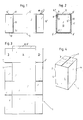
- - Figure 1 illustrates schematically a first embodiment of an inventive fixture, seen transversely to the longitudinal axis of the fixture;
- - Figure 2 illustrates the fixture of Figure 1, seen from the right of said Figure;
- - Figure 3 illustrates a sheet produced with the aid of and in accordance with a fixture substantially of the kind illustrated in Figures 1 and 2;
- - Figure 4 is a perspective view of a carton or box produced from a sheet substantially according to Figure 3;
- - Figure 5 illustrates schematically a knife arrangement for producing flap parts of a sheet, and illustrates the fixture as seen in Figure 2;
- - Figure 6 illustrates schematically the arrangement shown in Figure 5, seen from the left in said Figure; and
- - Figure 7 is a schematic, central longitudinal sectional view of an embodiment of an inventive fixture provided with collapsible support parts.
- In Figure 4, the
reference numeral 1 identifies a carton produced in accordance with the invention, while in Figure 3 the reference numeral 1' identifies a continuous, finished sheet produced from a sheet blank having a size which includes at least said finished sheet. - The
carton 1 comprises a substantially tubular, not necessarily cylindrical,carton part 2, which in the illustrated embodiment has a substantially rectangular outer cross-sectional profile,flap parts 3 located preferably at each of the two ends of said carton part, these flap parts functioning to close the tubular carton part. - In cross-section, the illustrated carton part is constructed from a continuous row of sequentially disposed carton members which form
side parts 4, Figure 3. - In Figures 1 and 2, the
reference numeral 5 identifies a fixture which has a longitudinal extension that corresponds to the longitudinal extension of the tubular carton part, and a cross-sectional outer profile which corresponds substantially to the cross-sectional outer profile of thetubular carton part 2. The illustratedfixture 5 includes attachment devices 6 in the form of elongated retaining slots 7 which are intended to receive an edge part 8 of a sheet blank, preferably contiguous with anelongated corner part 9 thereof, saidcorner part 9 forming a demarcation part between two mutuallyadjacent side parts 4; a sheet blank is intended to be folded, wrapped, around the fixture, Figure 2, to form thetubular carton part 2 and also flap parts as a continuation of the carton part. The fixture is also intended to form a template to facilitate remova- excessive parts of a sheet blank mounted on the fixture, when necessary. - An edge part 8 of a sheet blank is intended to be inserted into said retaining slot 7 and folded and retained, such as to form from said edge part 8 a securing flap 8' by means of which, when constructed, the tubular carton part is held together in a known manner.
- According to one preferred embodiment, illustrated in Figure 1, the slot 7 has a predetermined depth to which the edge part 8 can be inserted, the depth of said slot 7 functioning to determine the length of the securing flap transversely to the longitudinal direction, i.e. in the circumferential direction of the tubular carton part.
- Projecting substantially in the aforesaid longitudinal direction, from the part 5', a central part 5', of the fixture, said part corresponding to the
tubular carton part 2, aresupport parts 5" which form cutting slits 9' which enable the fixture to be used as a template or the like when forming saidflap parts 3 with the aid of cuts 3' made substantially in the longitudinal direction of the fixture. - According to one preferred embodiment, the fixture includes externally mounted
strips 10 which extend substantially transversely to said longitudinal direction at the ends of the central part 5', saidstrips 10 functioning to produce bending lines 11, Figure 3, in the junction between the tubular carton part and the flap parts, primarily by being pressed into the sheet blank. - In the case of the embodiment of the fixture illustrated primarily in Figures 1 and 2, the fixture comprises a substantially tubular, but not necessarily cylindrical, body having a central part 5' which functions to form the
tubular carton part 2, and twoend parts 12 which adjoin the central part 5'. Theend parts 12 form support parts which function to form flap parts and which include requisite cutting slots or slits, in the illustrated case corner-located slits, which is typical with such apparatus. The body of the fixture includes two, internally locatedend walls 13, where one end wall is located at the junction between the central part 5' andrespective end parts 12. The end walls have a stiffening and retaining effect. As with the illustrated case, the retaining slot 7 can be given a predetermined depth, by providing a recess 7' in each end wall, as seen from Figure 2. - According to another embodiment of the fixture, the fixture can be rotated about a longitudinal axle or shaft. As illustrated in Figures 5 and 6 in the case of this embodiment, an axle or
shaft 14 extends at least from oneend wall 13 or the like and is connected to means (not shown) for rotation of the fixture. According to a further embodiment, aknife arrangement 15 or the like is provided for the purpose of forming said flap parts as the fixture is rotated. In the case of the illustrated embodiment,sleeve 17 carrying knife means is arranged to move on the axle orshaft 14 and is held substantially against rotation on theshaft 14 by means of a wedge-like latching arrangement 16, said knife means being intended to move in the cutting slits. - Figure 7 illustrates an embodiment of the inventive fixture in which the support parts can be folded or collapsed to and extended from an end-wall position, as indicated by the
arrows 19. In this case, when the arrangement includes foursupport parts 5" at respective ends of the fixture, the support parts are preferably capable of being collapsed and extended in pairs. Embodiments are conceivable in which only two mutually opposingsupport parts 5" are provided at each end of the fixture. In this case, cutting slits are formed by omitting two side parts, cutting of the sheet being effected along the longitudinal edges of said support parts. In the case of embodiments which include foldable support parts, nostrips 10 are required for producing folding lines, since folding of theflap parts 3 can be effected along thewall edge 20 of the central part. - The
support parts 5" are preferably capable of being fixed in their respective end-wall positions, with the aid of suitable latching devices, and optionally of being returned from the end-wall position under the action ofspring forces 21, as illustrated in Figure 7. - The manner in which the inventive apparatus works, and also the working steps of the inventive method, will be understood in all essentials from the aforegoing. Thus, one edge part of a sheet blank, which may consist of a piece of a used, larger carton or box, is appropriately attached to the fixture and the sheet blank rotated so as to wrap around the fixture. Protruding parts of the sheet blank are cut away and flap parts are formed by means of substantially longitudinally extending cuts. A sheet blank mounted on the fixture is shown in broken lines in Figure 2.
- In the case of the embodiment illustrated in Figure 7, a carton or
box 1 can be produced essentially on the fixture. In this case, cuts are made along thelines 3" to provideflap parts 3, whereafter the flap parts at one end of the fixture, and also the end-wall parts, are folded to an end-wall position in order to close one end of the carton or box, whereafter said parts are secured permanently with the aid of adhesive tape or the like. The flap parts at the other end are folded in a corresponding manner, although closure of the box or carton is not made permanent and the flap parts, and suitably also the support parts, can be re- extended to an open position, whereafter the fixture, possibly with the aid of aninternal handle 22, is lifted from the carton or box thus constructed. - It will be understood from the aforegoing that the method and apparatus according to the invention provide a solution to the aforesaid problem of producing cartons, boxes and the like in a rational manner at low cost.
- Although the invention has been described with reference to illustrative embodiments thereof, it will be understood that other embodiments and minor modifications to those embodiments shown are conceivable, without departing from the concept of the invention.
- For instance, cartons in which the
tubular carton part 2 comprises a desired number ofside parts 4, for instance three such parts, can be produced, by appropriate configuration of the cross-sectional outer profile of the central part of the fixture. - Furthermore, it is conceivable to provide
flap parts 3 solely at one end of thecarton part 2. It is also conceivable provide flap parts solely at certain side parts. - Those cuts 3" by means of which the flap parts are formed can, of course, be produced in a manner different to that described. For instance, the cuts can be made manually with the aid of a knife, such as the
knife 18 shown in Figure 1. - The invention shall not therefore be considered as limited to the aforedescribed and illustrated embodiments, since modifications can be made within the scope of the following Claims.
Claims (19)
Priority Applications (1)
| Application Number | Priority Date | Filing Date | Title |
|---|---|---|---|
| DE69014622T DE69014622T2 (en) | 1990-08-24 | 1990-08-24 | Method and device for producing a preformed sheet foldable into a carton. |
Applications Claiming Priority (1)
| Application Number | Priority Date | Filing Date | Title |
|---|---|---|---|
| SE8900679A SE465716B (en) | 1989-02-27 | 1989-02-27 | DEVICE AND PROCEDURE TO MAKE A SHEET INTENDED TO BE FOLDED TO A CARTON |
Publications (2)
| Publication Number | Publication Date |
|---|---|
| EP0471915A1 true EP0471915A1 (en) | 1992-02-26 |
| EP0471915B1 EP0471915B1 (en) | 1994-11-30 |
Family
ID=20375179
Family Applications (1)
| Application Number | Title | Priority Date | Filing Date |
|---|---|---|---|
| EP90850283A Expired - Lifetime EP0471915B1 (en) | 1989-02-27 | 1990-08-24 | A method for manufacturing a preformed sheet intended to be folded to a carton and an apparatus for carrying out the method |
Country Status (3)
| Country | Link |
|---|---|
| US (1) | US5147269A (en) |
| EP (1) | EP0471915B1 (en) |
| SE (1) | SE465716B (en) |
Families Citing this family (4)
| Publication number | Priority date | Publication date | Assignee | Title |
|---|---|---|---|---|
| US5569148A (en) * | 1992-11-23 | 1996-10-29 | Bay Corrugated Container, Inc. | Method and apparatus for manufacturing pallet spacers |
| US6106450A (en) * | 1998-06-01 | 2000-08-22 | Georgia-Pacific Corporation | Apparatus and method for set-up of a non-rectangular container from a knocked-down-flat (KDF) precursor |
| CA2259785C (en) | 1999-01-19 | 2008-07-29 | Peter E. Sandford | Jogger member, system and method for mounting jogger members and female and male blanking dies provided therewith |
| FI124705B (en) * | 2012-07-12 | 2014-12-15 | Jomet Oy | Hardware for adjusting the height of the packing box and closing the box |
Citations (8)
| Publication number | Priority date | Publication date | Assignee | Title |
|---|---|---|---|---|
| BE501082A (en) * | ||||
| US2772609A (en) * | 1953-09-30 | 1956-12-04 | Highland Box Company | Box machine |
| GB821546A (en) * | 1955-05-26 | 1959-10-07 | Robert Morris Bergstein | Apparatus and method for forming cartons and like containers |
| US2915932A (en) * | 1957-01-15 | 1959-12-08 | Union Bag Camp Paper Corp | Device for simultaneously cutting the corners of a box to provide closure flaps |
| GB952699A (en) * | 1961-11-03 | 1964-03-18 | Hesser Ag Maschf | Machine for the manufacture of packaging bags |
| FR1552283A (en) * | 1966-12-02 | 1969-01-03 | ||
| DE1815710A1 (en) * | 1967-12-18 | 1969-10-16 | Gianfranco Beretta | Machine for the serial and cheap production of cardboard wrappings for small metal articles, especially nails or the like. |
| DE1901380A1 (en) * | 1969-01-13 | 1970-09-17 | Otto Schrebb | Machine for the fully automatic production of cardboard bags for nails, pins, screws, rivets, etc. |
Family Cites Families (9)
| Publication number | Priority date | Publication date | Assignee | Title |
|---|---|---|---|---|
| US1882049A (en) * | 1919-07-07 | 1932-10-11 | American Mach & Foundry | Lined receptacles |
| US1528073A (en) * | 1924-03-29 | 1925-03-03 | Mojonnier Bros Co | Container-forming machine |
| US2759544A (en) * | 1954-07-16 | 1956-08-21 | Vries Benjamin S De | Implement for severing a paper container at a selected point in its length |
| US2826969A (en) * | 1956-02-06 | 1958-03-18 | Crown Zellerbach Corp | Box fabricating mandrel |
| US3015197A (en) * | 1960-07-15 | 1962-01-02 | Ibm | Carton slitter and forming machine |
| US4308020A (en) * | 1978-04-27 | 1981-12-29 | H. J. Langen & Sons Limited | Mandrel of wrap-around carton forming machine to provide tight fit about enclosed item |
| US4441948A (en) * | 1981-10-28 | 1984-04-10 | Macmillan Bloedel Limited | Method and apparatus for constructing multiple layer corrugated board containers |
| US4659322A (en) * | 1985-08-23 | 1987-04-21 | Boudin Leon L | Apparatus and method for producing a resealable container |
| FR2629012B1 (en) * | 1988-03-22 | 1994-01-14 | Embal Systems | PROCESS AND MACHINE FOR MAKING POLYGONAL SECTION CRATES IN SHEET MATERIAL AND CRATES THUS OBTAINED |
-
1989
- 1989-02-27 SE SE8900679A patent/SE465716B/en not_active IP Right Cessation
-
1990
- 1990-08-24 EP EP90850283A patent/EP0471915B1/en not_active Expired - Lifetime
- 1990-08-24 US US07/572,225 patent/US5147269A/en not_active Expired - Fee Related
Patent Citations (8)
| Publication number | Priority date | Publication date | Assignee | Title |
|---|---|---|---|---|
| BE501082A (en) * | ||||
| US2772609A (en) * | 1953-09-30 | 1956-12-04 | Highland Box Company | Box machine |
| GB821546A (en) * | 1955-05-26 | 1959-10-07 | Robert Morris Bergstein | Apparatus and method for forming cartons and like containers |
| US2915932A (en) * | 1957-01-15 | 1959-12-08 | Union Bag Camp Paper Corp | Device for simultaneously cutting the corners of a box to provide closure flaps |
| GB952699A (en) * | 1961-11-03 | 1964-03-18 | Hesser Ag Maschf | Machine for the manufacture of packaging bags |
| FR1552283A (en) * | 1966-12-02 | 1969-01-03 | ||
| DE1815710A1 (en) * | 1967-12-18 | 1969-10-16 | Gianfranco Beretta | Machine for the serial and cheap production of cardboard wrappings for small metal articles, especially nails or the like. |
| DE1901380A1 (en) * | 1969-01-13 | 1970-09-17 | Otto Schrebb | Machine for the fully automatic production of cardboard bags for nails, pins, screws, rivets, etc. |
Also Published As
| Publication number | Publication date |
|---|---|
| SE8900679L (en) | 1990-08-28 |
| SE8900679D0 (en) | 1989-02-27 |
| US5147269A (en) | 1992-09-15 |
| EP0471915B1 (en) | 1994-11-30 |
| SE465716B (en) | 1991-10-21 |
Similar Documents
| Publication | Publication Date | Title |
|---|---|---|
| FI83300C (en) | Corrugated cardboard container with folding tabs | |
| EP0681963A1 (en) | Divider for foldable cardboard boxes and a method for manufacturing said divider | |
| US4951867A (en) | Folding separator | |
| JPH08238690A (en) | Method and device for forming box material having slot and fold | |
| US5314062A (en) | Innerframe and apparatus for producing an improved innerframe | |
| US1373365A (en) | Foldable box | |
| EP0471915B1 (en) | A method for manufacturing a preformed sheet intended to be folded to a carton and an apparatus for carrying out the method | |
| US4067492A (en) | Slotted dividers for shipping cartons | |
| EP3562748B1 (en) | Reinforced box and method of manufacturing such box | |
| US5152737A (en) | Improved innerframe and apparatus for producing an improved innerframe | |
| DE2523663B2 (en) | CARDBOARD BLOCK | |
| US3700159A (en) | Foldable container and blanks therefor | |
| EP1484263B1 (en) | Method for packing an electric lamp | |
| GB2086850A (en) | Carton | |
| DE602004004522T2 (en) | Fully enclosed box and blank | |
| EP3414171B1 (en) | Container assembly having a cell assembly therein | |
| GB2137168A (en) | Tray Blank | |
| WO1996015902A2 (en) | Process and folding blanks for the production of folded cartons | |
| JPH04107132A (en) | Method and device for manufacturing carton, box or like | |
| US2923211A (en) | Box and method and apparatus for the manufacture thereof | |
| EP0784015A1 (en) | Vial-containing box, formed from a single punched cardboard sheet | |
| EP0800998A1 (en) | Foldable container | |
| JP2668639B2 (en) | Foldable packaging | |
| DE202019001390U1 (en) | protective packaging | |
| GB2240766A (en) | Corrugated-cardboard packaging box and manufacturing method thereof |
Legal Events
| Date | Code | Title | Description |
|---|---|---|---|
| PUAI | Public reference made under article 153(3) epc to a published international application that has entered the european phase |
Free format text: ORIGINAL CODE: 0009012 |
|
| AK | Designated contracting states |
Kind code of ref document: A1 Designated state(s): DE DK FR GB IT |
|
| 17P | Request for examination filed |
Effective date: 19920807 |
|
| 17Q | First examination report despatched |
Effective date: 19930716 |
|
| GRAA | (expected) grant |
Free format text: ORIGINAL CODE: 0009210 |
|
| AK | Designated contracting states |
Kind code of ref document: B1 Designated state(s): DE DK FR GB IT |
|
| PG25 | Lapsed in a contracting state [announced via postgrant information from national office to epo] |
Ref country code: IT Free format text: LAPSE BECAUSE OF FAILURE TO SUBMIT A TRANSLATION OF THE DESCRIPTION OR TO PAY THE FEE WITHIN THE PRE;WARNING: LAPSES OF ITALIAN PATENTS WITH EFFECTIVE DATE BEFORE 2007 MAY HAVE OCCURRED AT ANY TIME BEFORE 2007. THE CORRECT EFFECTIVE DATE MAY BE DIFFERENT FROM THE ONE RECORDED.SCRIBED TIME-LIMIT Effective date: 19941130 Ref country code: DK Effective date: 19941130 |
|
| ET | Fr: translation filed | ||
| REF | Corresponds to: |
Ref document number: 69014622 Country of ref document: DE Date of ref document: 19950112 |
|
| PG25 | Lapsed in a contracting state [announced via postgrant information from national office to epo] |
Ref country code: GB Effective date: 19950824 |
|
| PLBE | No opposition filed within time limit |
Free format text: ORIGINAL CODE: 0009261 |
|
| STAA | Information on the status of an ep patent application or granted ep patent |
Free format text: STATUS: NO OPPOSITION FILED WITHIN TIME LIMIT |
|
| 26N | No opposition filed | ||
| GBPC | Gb: european patent ceased through non-payment of renewal fee |
Effective date: 19950824 |
|
| PG25 | Lapsed in a contracting state [announced via postgrant information from national office to epo] |
Ref country code: FR Effective date: 19960430 |
|
| PG25 | Lapsed in a contracting state [announced via postgrant information from national office to epo] |
Ref country code: DE Effective date: 19960501 |
|
| REG | Reference to a national code |
Ref country code: FR Ref legal event code: ST |