EP0471884A1 - Electrohydraulic servovalve - Google Patents
Electrohydraulic servovalve Download PDFInfo
- Publication number
- EP0471884A1 EP0471884A1 EP19900116279 EP90116279A EP0471884A1 EP 0471884 A1 EP0471884 A1 EP 0471884A1 EP 19900116279 EP19900116279 EP 19900116279 EP 90116279 A EP90116279 A EP 90116279A EP 0471884 A1 EP0471884 A1 EP 0471884A1
- Authority
- EP
- European Patent Office
- Prior art keywords
- spool
- pressure
- servo valve
- control
- valve
- Prior art date
- Legal status (The legal status is an assumption and is not a legal conclusion. Google has not performed a legal analysis and makes no representation as to the accuracy of the status listed.)
- Granted
Links
- 230000007935 neutral effect Effects 0.000 claims abstract description 8
- 230000001419 dependent effect Effects 0.000 claims abstract 2
- 238000004519 manufacturing process Methods 0.000 description 2
- 101100400378 Mus musculus Marveld2 gene Proteins 0.000 description 1
- 230000000903 blocking effect Effects 0.000 description 1
- 230000003247 decreasing effect Effects 0.000 description 1
- 239000012530 fluid Substances 0.000 description 1
- 238000000034 method Methods 0.000 description 1
Images

Classifications
-
- F—MECHANICAL ENGINEERING; LIGHTING; HEATING; WEAPONS; BLASTING
- F15—FLUID-PRESSURE ACTUATORS; HYDRAULICS OR PNEUMATICS IN GENERAL
- F15B—SYSTEMS ACTING BY MEANS OF FLUIDS IN GENERAL; FLUID-PRESSURE ACTUATORS, e.g. SERVOMOTORS; DETAILS OF FLUID-PRESSURE SYSTEMS, NOT OTHERWISE PROVIDED FOR
- F15B13/00—Details of servomotor systems ; Valves for servomotor systems
- F15B13/02—Fluid distribution or supply devices characterised by their adaptation to the control of servomotors
- F15B13/04—Fluid distribution or supply devices characterised by their adaptation to the control of servomotors for use with a single servomotor
- F15B13/042—Fluid distribution or supply devices characterised by their adaptation to the control of servomotors for use with a single servomotor operated by fluid pressure
- F15B13/043—Fluid distribution or supply devices characterised by their adaptation to the control of servomotors for use with a single servomotor operated by fluid pressure with electrically-controlled pilot valves
-
- Y—GENERAL TAGGING OF NEW TECHNOLOGICAL DEVELOPMENTS; GENERAL TAGGING OF CROSS-SECTIONAL TECHNOLOGIES SPANNING OVER SEVERAL SECTIONS OF THE IPC; TECHNICAL SUBJECTS COVERED BY FORMER USPC CROSS-REFERENCE ART COLLECTIONS [XRACs] AND DIGESTS
- Y10—TECHNICAL SUBJECTS COVERED BY FORMER USPC
- Y10T—TECHNICAL SUBJECTS COVERED BY FORMER US CLASSIFICATION
- Y10T137/00—Fluid handling
- Y10T137/8593—Systems
- Y10T137/86493—Multi-way valve unit
- Y10T137/86574—Supply and exhaust
- Y10T137/86582—Pilot-actuated
- Y10T137/8659—Variable orifice-type modulator
- Y10T137/86598—Opposed orifices; interposed modulator
-
- Y—GENERAL TAGGING OF NEW TECHNOLOGICAL DEVELOPMENTS; GENERAL TAGGING OF CROSS-SECTIONAL TECHNOLOGIES SPANNING OVER SEVERAL SECTIONS OF THE IPC; TECHNICAL SUBJECTS COVERED BY FORMER USPC CROSS-REFERENCE ART COLLECTIONS [XRACs] AND DIGESTS
- Y10—TECHNICAL SUBJECTS COVERED BY FORMER USPC
- Y10T—TECHNICAL SUBJECTS COVERED BY FORMER US CLASSIFICATION
- Y10T137/00—Fluid handling
- Y10T137/8593—Systems
- Y10T137/86493—Multi-way valve unit
- Y10T137/86574—Supply and exhaust
- Y10T137/86582—Pilot-actuated
- Y10T137/86614—Electric
Definitions
- the invention relates to an electrohydraulic proportional or servo valve according to the preamble of claim 1.
- Control loops are increasingly being used by machine manufacturers to increase product quality and the degree of automation.
- a typical application is the electro-hydraulic position control loop.
- the proportional valve has an important function. It must convert an electrical signal quickly and accurately into an appropriate flow or pressure. In these applications, it is particularly important to keep the controlled variable within narrow tolerances. Therefore, a strictly linear characteristic between the electrical control signal and the flow must be requested.
- proportional valves are characterized by the fact that constructive improvements were aimed at minimizing the so-called dead band range of the valve characteristic.
- dead band range of the valve characteristic.
- the present invention has for its object to provide a linear servo valve of the type mentioned, in which, despite good linearity, a standstill of the consumer is guaranteed in the rest position.
- the present invention makes use of the knowledge that it is not so important to make the valve itself linear in terms of its mechanical structure, but that a linear valve can also be achieved by deliberately choosing a non-linear valve which again uses an electrical circuit is made linear.
- Valves with a mechanical coverage area ensure a safe standstill of the consumer under load, since they reliably separate the pressure outlet channel from the pressure inlet channel even with the usual manufacturing tolerances when the control piston is in the neutral position.
- the proportional valve has a cylinder 1 with a central pressure inlet channel 2, two pressure outlet channels 3 and 4 arranged offset in the axial direction and a return channel 5 which is connected to the supply tank.
- a control piston 6 is mounted between two driver pistons 22.
- the end faces 7 of the driver pistons 22 can be acted upon by a control pressure in the axial direction via the control chambers 9 and 10.
- a pair of piston rings 11 are formed on the control piston above the two pressure outlet channels 3 and 4, respectively.
- the control piston has annular recesses between the piston rings 11 so that the hydraulic fluid can flow around the piston better.
- Corresponding (annular) chambers are formed in the opposite sections of the cylinder wall. The pressure on the piston rings 11 therefore acts on the entire circumference of the piston surface.
- the two pressure outlet channels 3, 4 have a diameter a, which corresponds to the thickness of the annular chambers.
- the two piston rings 11 are spaced apart in the axial direction such that the total thickness D of the two piston rings is greater than the thickness of the annular chambers (a) or the diameter of the pressure outlet openings 3 and 4 on the inside of the cylinder wall. Half of the difference between the total thickness D and the thickness of the annular chambers or the diameter of the pressure outlet channels (a) should define the positive overlap x.
- the maximum deflection of the control piston 6 from the rest position is to be denoted by y.
- the pressure-free outer spaces of the cylinder 1 are connected to one another via a compensating line 12 and the common return duct (5).
- the control piston 6 is axially centered in the valve housing by means of two springs 8, which also act on the end faces 7 of the driver piston 22. With the control piston 6, an electrical position sensor 13 is connected in an axial extension, which via an elek known from the prior art tric position control loop 20 is fed back to a torque motor 14.
- the position control loop and compensation circuit 21 according to the invention are located in an electrically insulated part of the valve housing.
- the armature 15 of the torque motor 14 acts directly on the baffle plate 16 of a nozzle 17 baffle plate 16 system.
- the control rooms 9 and 10 have a bypass channel 18 and an electrically operated valve 19 located in this channel in order to be connected to one another when the valve is open.
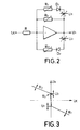
- the circuit shows a preferred embodiment of the compensation circuit.
- the circuit consists of an inverting amplifier with an input resistor R and a feedback circuit consisting of three feedback branches which act on the negative input of the operational amplifier.
- One of these feedback branches only consists of an adjustable ohmic resistor R 3 , the other two each consist of a series connection of an adjustable voltage source U 1 or U 2 , a diode D 1 and D 2 and an adjustable resistor R 1 or R 2 .
- the diodes D 1 and D 2 are switched in the reverse direction with respect to the polarities of the voltage sources U 1 and U 2 .
- Fig. 3 the relationship between the input and the output signal is shown graphically.
- the graph is defined in sections by the equations given above.
- the slopes of the straight sections are determined by the ratios of the feedback resistors Ri, R 2 , and R 3 to the input resistance R. The lower the ratio, the flatter the respective straight line section.
- variable voltage sources U and U 2 are decisive for the position of the break points of the non-linearity. Increasing or decreasing the voltage shifts the respective inflection point in the direction of the positive and negative Y-axis of the graph in Fig. 3.
- the return duct with the resistor R 3 that is always effective, is specified in dependence on the output signal in the above- Way connected in parallel to either resistor R 1 or R 2 .
- valve 19 located in the bypass channel 18 opens when the power supply is interrupted, the control chambers 9, 10 are hydraulically short-circuited. As a result, an existing pressure difference in the control chambers is immediately equalized and the return springs 8 move the control piston 6 into the area of positive overlap. Here the absolute safe standstill of the consumer is guaranteed, since no leakage currents can occur in the overlap area. This takes into account the need for security.
Landscapes
- Engineering & Computer Science (AREA)
- Physics & Mathematics (AREA)
- Fluid Mechanics (AREA)
- Mechanical Engineering (AREA)
- General Engineering & Computer Science (AREA)
- Servomotors (AREA)
Abstract
Description
Die Erfindung bezieht sich auf ein elektrohydraulisches Proportional- oder Servoventil nach dem Oberbegriff des Anspruchs 1.The invention relates to an electrohydraulic proportional or servo valve according to the preamble of claim 1.
Regelkreise werden von Maschinenherstellern zunehmend zur Steigerung von Produktqualität und des Automatisierungsgrades eingesetzt. Eine typische Anwendung ist der elektrohydraulische Lageregelkreis.Control loops are increasingly being used by machine manufacturers to increase product quality and the degree of automation. A typical application is the electro-hydraulic position control loop.
Eine wichtige Eunktion hat dabei das Proportionalventil. Es muß ein elektrisches Signal schnell und genau in einen entsprechenden Durchfluß oder Druck umwandeln. Insbesondere ist es bei diesen Anwendungen wichtig, die Regelgröße in engen Toleranzen zu halten. Deshalb ist eine streng lineare Kennlinie zwischen dem elektrischen Steuersignal und dem Durchfluß zu fordern.The proportional valve has an important function. It must convert an electrical signal quickly and accurately into an appropriate flow or pressure. In these applications, it is particularly important to keep the controlled variable within narrow tolerances. Therefore, a strictly linear characteristic between the electrical control signal and the flow must be requested.
Die Entwicklung der Proportionalventile ist dadurch gekennzeichnet, daß konstruktive Verbesserungen zum Ziel hatten, den sogenannten Totbandbereich der Ventilkennlinie zu minimieren. Dabei trat zwangsweise die Problematik auf, daß bei Ventilen, bei denen der Totbandbereich zugunsten der Linearität gering gehalten wurde, Leckströme aufgrund der mechanischen Fertigungstoleranzen auftreten.The development of proportional valves is characterized by the fact that constructive improvements were aimed at minimizing the so-called dead band range of the valve characteristic. Inevitably, the problem arose that in valves in which the dead band area was kept small in favor of linearity, leakage currents occur due to the mechanical manufacturing tolerances.
Genaue Linearität und Sicherheit in der neutralen Stellung sind in Servoventilen wegen der angesprochenen Leckströme nicht vereinbar. Die geforderte Sicherheit kann nur mit zusätzlichen Mitteln realisiert werden.Exact linearity and safety in the neutral position are not compatible in servo valves due to the leakage currents mentioned. The required security can only be achieved with additional means.
Der vorliegenden Erfindung liegt die Aufgabe zugrunde, ein lineares Servoventil der eingangs genannten Art anzugeben, bei dem trotz guter Linearität ein Stillstand des Verbrauchers in der Ruhestellung gewährleistet ist.The present invention has for its object to provide a linear servo valve of the type mentioned, in which, despite good linearity, a standstill of the consumer is guaranteed in the rest position.
Diese Aufgabe wird, gemäß vorliegender Erfindung durch die Merkmale des Anspruchs 1 gelöst.This object is achieved according to the present invention by the features of claim 1.
Die vorliegende Erfindung nutzt die Erkenntnis, daß es nicht so wichtig ist, das Ventil selbst von seinem mechanischen Aufbau linear zu gestalten, sondern daß ein lineares Ventil auch dadurch erreicht werden kann, daß man bewußt ein nichtlineares Ventil wählt, das mit einer elektrischen Schaltung wieder linear gemacht wird.The present invention makes use of the knowledge that it is not so important to make the valve itself linear in terms of its mechanical structure, but that a linear valve can also be achieved by deliberately choosing a non-linear valve which again uses an electrical circuit is made linear.
Ventile mit einem mechanischen Überdekkungsbereich gewährleisten einen sicheren Stillstand des unter Last stehenden Verbrauchers, da sie auch bei den üblichen Fertigungstoleranzen den Druckauslaßkanal zuverlässig von dem Druckeinlaßkanal trennen, wenn sich der Steuerkolben in der neutralen Stellung befindet.Valves with a mechanical coverage area ensure a safe standstill of the consumer under load, since they reliably separate the pressure outlet channel from the pressure inlet channel even with the usual manufacturing tolerances when the control piston is in the neutral position.
Dadurch erhält das Ventil aber eine nicht lineare Charakteristik. Durch die elektrische Kompensationsschaltung wird die Linearität wieder vollständig erreicht, ohne aber den angesprochenen Sicherheitsvorteil aufgeben zu müssen.This gives the valve a non-linear characteristic. The linearity is completely achieved again by the electrical compensation circuit, but without having to give up the safety advantage mentioned.
Mit dem zusätzlichen Bypasskanal und dem darin gelagerten Elektroventil wird weiterhin sichergestellt, daß das Servoventil sehr schnell, beispielsweise bei Stromausfall sofort in seine Ruhestellung übergeht, in der die Last absolut stillsteht.With the additional bypass channel and the electrovalve stored in it, it is further ensured that the servo valve switches to its idle position very quickly, for example in the event of a power failure, in which the load is absolutely stationary.
Im folgenden wird die Erfindung anhand einer in der Zeichnung dargestellten Ausführungsform erläutert.
- Fig. 1 zeigt ein Schnittbild eines Proportionalventils zweistufiger Bauart;
- Fig. 2 zeigt eine bevorzugte Ausführung der Kompensationsschaltung.
- Fig. 3 zeigt den Zusammenhang zwischen Ausgangs- und Eingangsspannung der Kompensationsschaltung.
- Fig. 1 shows a sectional view of a proportional valve of two-stage design;
- Fig. 2 shows a preferred embodiment of the compensation circuit.
- Fig. 3 shows the relationship between the output and input voltage of the compensation circuit.
Das Proportionalventil weist einen Zylinder 1 mit einem mittigen Druckeinlaßkanal 2, zwei in axialer Richtung versetzt angeordnete Druckauslaßkanäle 3 und 4 sowie einen Rückführkanal 5, der mit dem Versorgungstank verbunden ist, auf.The proportional valve has a cylinder 1 with a central
In dem Zylinder 1 ist zwischen zwei Treiberkolben 22 ein Steuerkolben 6 gelagert. Die Stirnflächen 7 der Treiberkolben 22 können über die Steuerräume 9 und 10 mit einem Steuerdruck in axialer Richtung beaufschlagt werden. An dem Steuerkolben sind jeweils über den beiden Druckauslaßkanälen 3 bzw. 4 ein Paar Kolbenringe 11 ausgebildet. Der Steuerkolben besitzt zwischen den Kolbenringen 11 ringförmige Ausnehmungen, damit die hydraulische Flüssigkeit den Kolben besser umfließen kann. In den gegenüber stehenden Abschnitten der Zylinderwand sind entsprechende (ringförmige) Kammern ausgebildet. Der Druck auf die Kolbenringe 11 wirkt daher auf den gesamten Umfang der Kolbenfläche. Die beiden Druckauslaßkanäle 3, 4 besitzen einen Durchmesser a, welcher der Dicke der ringförmigen Kammern entspreche. Die beiden Kolbenringe 11 besitzen einen Anstand in axialer Richtung voneinander derart, daß die Gesamtdicke D der beiden Kolbenringe größer ist als die Dicke der ringförmigen Kammern (a) bzw. der Durchmesser der Druckauslaßöffnungen 3 bzw. 4 an der Zylinderwandinnenseite. Die Hälfte der Differenz zwischen der Gesamtdicke D und der Dicke der ringförmigen Kammern bzw. dem Durchmesser der Druckauslaßkanäle (a) soll die positive Überdekkung x definieren. Die maximale Auslenkung des Steuerkolbens 6 aus der Ruhestellung soll mit y bezeichnet werden.In the cylinder 1, a
Die druckfreien Außenräume des Zylinders 1 stehen über eine Ausgleichsleitung 12 und dem gemeinsamen Rückführkanal (5) miteinander in Verbindung.The pressure-free outer spaces of the cylinder 1 are connected to one another via a
Der Steuerkolben 6 ist in axialer Richtung über zwei Federn 8, die ebenfalls auf die Stirnflächen 7 der Treiberkolben 22 wirken, in der Nullstellung mittig zentriert im Ventilgehäuse gelagert. Mit dem Steuerkolben 6 ist in axialer Verlängerung ein elektrischer Lageaufnehmer 13 verbunden, der über einen aus dem Stand der Technik bekannten elektrischen Lageregelkreis 20 auf einen Torquemotor 14 rückgekoppelt ist. Lageregelkreis und Kompensationsschaltung 21 gemäß der Erfindung befinden sich in einem elektrisch isolierten Teil des Ventilgehäuses. Der Anker 15 des Torquemotors 14 wirkt direkt auf die Prallplatte 16 eines Düse 17-Prallplatte 16-Systems.The
Die Steuerräume 9 und 10 weisen einen Bypasskanal 18 und ein in diesem Kanal liegendes elektrisch zu betätigendes Ventil 19 auf, um bei geöffnetem Ventil miteinander verbunden zu werden.The
In Fig. 2 ist eine bevorzugte Ausführungsform der Kompensationsschaltung dargestellt. Die Schaltung besteht aus einem invertierenden Verstärker mit einem Eingangswiderstand R und einer Rückkopplungsschaltung, bestehend aus drei Rückkopplungszweigen, die auf den negativen Eingang des Operationsverstärkers rückwirken. Einer dieser Rückkopplungszweige besteht lediglich aus einem einstellbaren ohmschen Widerstand R3, die beiden anderen jeweils aus der Serienschaltung einer einstellbaren Spannungsquelle U1 bzw. U2, einer Diode D1 und D2 und einem einstellbaren Widerstand R1 bzw. R2. Die Dioden D1 bzw. D2 sind in bezug auf die Polaritäten der Spannungsquellen U1 bzw. U2 in Sperrichtung geschaltet.2 shows a preferred embodiment of the compensation circuit. The circuit consists of an inverting amplifier with an input resistor R and a feedback circuit consisting of three feedback branches which act on the negative input of the operational amplifier. One of these feedback branches only consists of an adjustable ohmic resistor R 3 , the other two each consist of a series connection of an adjustable voltage source U 1 or U 2 , a diode D 1 and D 2 and an adjustable resistor R 1 or R 2 . The diodes D 1 and D 2 are switched in the reverse direction with respect to the polarities of the voltage sources U 1 and U 2 .
Nimmt man ideale Bauteile an, so gelten folgende Zusammenhänge zwischen Ausgangs (UA)-und Eingangsspannung (UE):
- UA = - UE . R3/R für U1 < UA < U2 UA = - UE . Ri/R für UA < U1 und R3 » R1 UA = - UE . R2/R für UA > U2 und R3 » R2
- U A = - U E. R 3 / R for U 1 <U A <U 2 U A = - UE. Ri / R for U A <U 1 and R 3 »R 1 U A = - U E. R 2 / R for U A > U 2 and R 3 »R 2
In Fig. 3 ist der Zusammenhang zwischen dem Eingangs- und dem Ausgangssignal graphisch dargestellt. Der Graph ist abschnittsweise durch die obenangegebenen Gleichungen definiert.In Fig. 3 the relationship between the input and the output signal is shown graphically. The graph is defined in sections by the equations given above.
Die Steigungen der geraden Abschnitte werden durch die Verhältnisse der Rückkopplungswiderstände Ri , R2, und R3 zum Eingangswiderstand R bestimmt. Je geringer das Verhältnis, desto flacher verläuft der jeweilige Geradenabschnitt.The slopes of the straight sections are determined by the ratios of the feedback resistors Ri, R 2 , and R 3 to the input resistance R. The lower the ratio, the flatter the respective straight line section.
Maßgebend für die Lage der Knickpunkte der Nichtlinearität sind die variablen Spannungsquellen U, und U2. Ein Erhöhen bzw. Erniedrigen der Spannung verschiebt den jeweiligen Knickpunkt in Richtung der positiven bzw. negativen Y-Achse des Diagramms in Fig. 3. Der Rückführkanal mit dem Widerstand R3, der immer wirksam ist, wird in Abhängigkeit vom Ausgangssignal in der oben angegebenen Weise parallel entweder zum Widerstand R1 oder R2 geschaltet.The variable voltage sources U and U 2 are decisive for the position of the break points of the non-linearity. Increasing or decreasing the voltage shifts the respective inflection point in the direction of the positive and negative Y-axis of the graph in Fig. 3. The return duct with the resistor R 3 that is always effective, is specified in dependence on the output signal in the above- Way connected in parallel to either resistor R 1 or R 2 .
Bereits ein sehr kleines positives Signal am Eingang der Kompensationsschaltung erzeugt an dessen Ausgang ein Signal der Amplitude U1. Dieses Signal verschiebt den Steuerkolben um die Auslenkung (x) aus seiner Runelage heraus. Dadurch beginnt sich der Druckauslaßkanal 4 bei einer weiteren Erhöhung des Eingangssignals sofort zu öffnen. Von diesem Knickpunkt an besteht ein linearer Zusammenhang zwischen dem elektrischen Stellsignal und dem Durchfluß durch das Ventil.Even a very small positive signal at the input of the compensation circuit generates a signal of amplitude U 1 at its output. This signal shifts the control piston out of its runelage by the deflection (x). As a result, the
Der gleiche Vorgang geschieht in umgekehrter Weise für ein negatives Signal am Eingang der Kompensationsschaltung und dem Druckauslaßkanal 3. Dabei entsprechen sich die Knickpunkte der elektrischen Nichtlinearität (Fig. 3) und die der durch die positive Überdeckung entstandene nichtlineare Ventilkennlinie. Das bedeutet aber praktisch nichts anderes als ein lineares Verhalten des Ventils nach außen hin. Der Totbandbereich wird quasi "übersprungen", ohne den Durchfluß durch das Ventil abzusperren. Damit zeigt das Ventil nach außen hin über den gesamten Arbeitsbereich lineares Verhalten.The same process takes place in reverse for a negative signal at the input of the compensation circuit and the
Öffnet sich bei einer Unterbrechung der Stromzufuhr das im Bypasskanal 18 liegende Ventil 19, werden die Steuerkammern 9, 10 hydraulisch kurzgeschlossen. Dadurch gleicht sich ein bestehender Druckunterschied in den Steuerkammern sofort aus und die Rückstellfedern 8 verschieben den Steuerkolben 6 in den Bereich positiver Überdeckung. Hier ist der absolute sichere Stillstand des Verbrauchers gewährleistet, da keine Leckströme im Überdeckungsbereich auftreten können. Damit wird dem Sicherheitsbedürfnis Rechnung getragen.If the
Claims (4)
Priority Applications (4)
| Application Number | Priority Date | Filing Date | Title |
|---|---|---|---|
| EP19900116279 EP0471884B1 (en) | 1990-08-24 | 1990-08-24 | Electrohydraulic servovalve |
| DE59010152T DE59010152D1 (en) | 1990-08-24 | 1990-08-24 | Electro-hydraulic servo valve |
| JP20564991A JPH0626501A (en) | 1990-08-24 | 1991-07-23 | Electronic hydraulic servo valve |
| US07/749,216 US5165448A (en) | 1990-08-24 | 1991-08-23 | Two-stage servovalve with compensatoin circuit to accommodate "dead zone" du |
Applications Claiming Priority (1)
| Application Number | Priority Date | Filing Date | Title |
|---|---|---|---|
| EP19900116279 EP0471884B1 (en) | 1990-08-24 | 1990-08-24 | Electrohydraulic servovalve |
Publications (2)
| Publication Number | Publication Date |
|---|---|
| EP0471884A1 true EP0471884A1 (en) | 1992-02-26 |
| EP0471884B1 EP0471884B1 (en) | 1996-02-21 |
Family
ID=8204370
Family Applications (1)
| Application Number | Title | Priority Date | Filing Date |
|---|---|---|---|
| EP19900116279 Expired - Lifetime EP0471884B1 (en) | 1990-08-24 | 1990-08-24 | Electrohydraulic servovalve |
Country Status (4)
| Country | Link |
|---|---|
| US (1) | US5165448A (en) |
| EP (1) | EP0471884B1 (en) |
| JP (1) | JPH0626501A (en) |
| DE (1) | DE59010152D1 (en) |
Cited By (2)
| Publication number | Priority date | Publication date | Assignee | Title |
|---|---|---|---|---|
| FR2694617A1 (en) * | 1992-08-06 | 1994-02-11 | Hr Textron Inc | Electro-hydraulic servo valve with gain compensation. |
| DE4227563A1 (en) * | 1992-08-20 | 1994-02-24 | Rexroth Mannesmann Gmbh | Electrohydraulic position regulator with two-stage proportional valve - has pilot electrohydraulic stage used to drive main fluid power stage with both having displacement sensors |
Families Citing this family (20)
| Publication number | Priority date | Publication date | Assignee | Title |
|---|---|---|---|---|
| US5884894A (en) * | 1996-08-20 | 1999-03-23 | Valtek, Inc. | Inner-loop valve spool positioning control apparatus |
| US6318182B1 (en) * | 1999-06-04 | 2001-11-20 | Eaton Corporation | Measurement of transmission oil pressure by monitoring solenoid current |
| CN1295441C (en) * | 2004-11-05 | 2007-01-17 | 宁波华液机器制造有限公司 | Proportional differential pressure control valve |
| RU2346187C2 (en) * | 2007-03-30 | 2009-02-10 | Валерий Иванович Разинцев | Three-stage electrohydraulic power amplifier |
| RU2489607C1 (en) * | 2011-12-09 | 2013-08-10 | Валерий Иванович Разинцев | Two-stage electrohydraulic amplifier with electric flow feedback |
| RU2467215C1 (en) * | 2011-09-27 | 2012-11-20 | Валерий Иванович Разинцев | Three-stage electrohydraulic amplifier with electric flow feedback |
| WO2013048283A1 (en) * | 2011-09-27 | 2013-04-04 | Razintsev Valery Ivanovich | Electrohydraulic amplifier with electrical feedback on consumption |
| RU2482341C1 (en) * | 2011-12-01 | 2013-05-20 | Валентин Григорьевич Жарков | Servo valve with jet control |
| RU2488719C1 (en) * | 2011-12-09 | 2013-07-27 | Валерий Иванович Разинцев | One-stage hydraulic booster with flow rate electric feedback |
| DE102014205041A1 (en) * | 2014-03-19 | 2015-09-24 | Robert Bosch Gmbh | Pressure reducing valve |
| JP6775288B2 (en) * | 2015-10-08 | 2020-10-28 | 株式会社堀場エステック | Fluid control valve and its control program |
| US10753376B2 (en) * | 2016-01-29 | 2020-08-25 | Komatsu Ltd. | Hydraulic cylinder spool valve device |
| US10927866B2 (en) | 2017-12-15 | 2021-02-23 | Eaton Intelligent Power Limited | Leakage modulation in hydraulic systems containing a three-way spool valve |
| JP7008499B2 (en) * | 2017-12-27 | 2022-01-25 | 株式会社堀場エステック | Calibration data creation device, calibration data creation method, and flow control device |
| GB2581160B (en) * | 2019-02-05 | 2022-10-19 | Domin Fluid Power Ltd | Rotary servo valve |
| EP3921550B1 (en) | 2019-02-05 | 2025-06-18 | Domin Limited | Rotary servo valve |
| CN110109348B (en) * | 2019-05-13 | 2023-03-10 | 河南工学院 | Depth-based hydraulic proportional valve bidirectional dead zone compensation method |
| US11473598B2 (en) | 2019-10-25 | 2022-10-18 | Woodward, Inc. | Failsafe electro-hydraulic servo valve |
| US11852250B2 (en) | 2022-04-11 | 2023-12-26 | Fisher Controls International Llc | Adjustable spool valve for a digital valve controller |
| CN119934105A (en) * | 2025-04-03 | 2025-05-06 | 苏州海卓伺服驱动技术有限公司 | Electro-hydraulic servo valve with rotary direct drive valve as pilot and control method thereof |
Citations (2)
| Publication number | Priority date | Publication date | Assignee | Title |
|---|---|---|---|---|
| FR2439920A1 (en) * | 1978-10-17 | 1980-05-23 | Bosch Gmbh Robert | Electrohydraulic valve with pre- and main control stages - uses only one proportional magnet and only one spring to load pre-control slide |
| EP0376023A2 (en) * | 1988-12-30 | 1990-07-04 | Robert Bosch Gmbh | Electrohydraulic proportional valve |
Family Cites Families (3)
| Publication number | Priority date | Publication date | Assignee | Title |
|---|---|---|---|---|
| US4192551A (en) * | 1978-10-10 | 1980-03-11 | Bethlehem Steel Corporation | Remote control system for mining machines |
| US4466337A (en) * | 1982-01-25 | 1984-08-21 | Sundstrand Corporation | Electro hydraulic control with dead zone compensation |
| US4766921A (en) * | 1986-10-17 | 1988-08-30 | Moog Inc. | Method of operating a PWM solenoid valve |
-
1990
- 1990-08-24 DE DE59010152T patent/DE59010152D1/en not_active Expired - Fee Related
- 1990-08-24 EP EP19900116279 patent/EP0471884B1/en not_active Expired - Lifetime
-
1991
- 1991-07-23 JP JP20564991A patent/JPH0626501A/en active Pending
- 1991-08-23 US US07/749,216 patent/US5165448A/en not_active Expired - Lifetime
Patent Citations (2)
| Publication number | Priority date | Publication date | Assignee | Title |
|---|---|---|---|---|
| FR2439920A1 (en) * | 1978-10-17 | 1980-05-23 | Bosch Gmbh Robert | Electrohydraulic valve with pre- and main control stages - uses only one proportional magnet and only one spring to load pre-control slide |
| EP0376023A2 (en) * | 1988-12-30 | 1990-07-04 | Robert Bosch Gmbh | Electrohydraulic proportional valve |
Non-Patent Citations (2)
| Title |
|---|
| OLHYDRAULIK UND PNEUMATIK. vol. 33, no. 10, Oktober 1989, MAINZ DE Seiten 786 - 789; berthold klug: "neue stetigventile zum steuern und regeln von plastverarbeitungsmachinen" * |
| ZEITSCHRIFT DES VEREINES DEUTSCHER INGENIEURE. vol. 128, no. 7, April 1986, DUSSELDORF DE Seiten 235 - 238; von gerd scheffel: "stetige richtungssteuerung" * |
Cited By (3)
| Publication number | Priority date | Publication date | Assignee | Title |
|---|---|---|---|---|
| FR2694617A1 (en) * | 1992-08-06 | 1994-02-11 | Hr Textron Inc | Electro-hydraulic servo valve with gain compensation. |
| DE4227563A1 (en) * | 1992-08-20 | 1994-02-24 | Rexroth Mannesmann Gmbh | Electrohydraulic position regulator with two-stage proportional valve - has pilot electrohydraulic stage used to drive main fluid power stage with both having displacement sensors |
| DE4227563C2 (en) * | 1992-08-20 | 2000-04-13 | Mannesmann Rexroth Ag | Controlled hydraulic feed drive |
Also Published As
| Publication number | Publication date |
|---|---|
| JPH0626501A (en) | 1994-02-01 |
| EP0471884B1 (en) | 1996-02-21 |
| DE59010152D1 (en) | 1996-03-28 |
| US5165448A (en) | 1992-11-24 |
Similar Documents
| Publication | Publication Date | Title |
|---|---|---|
| EP0471884A1 (en) | Electrohydraulic servovalve | |
| DE3688598T2 (en) | Devices for damping piston movements. | |
| DE2446963C2 (en) | Hydraulic control device | |
| DE3114437C2 (en) | Pressure control valve | |
| DE3130056A1 (en) | CONTROL VALVE ARRANGEMENT FOR A PRESSURE WORKING CYLINDER | |
| EP0620371B1 (en) | Hydraulic system for supply of open or closed hydraulic functions | |
| EP0864794A2 (en) | Proportional throttle valve | |
| EP0681128A1 (en) | Solenoid valve | |
| DE2305798B2 (en) | Hydraulic control device for a servomotor, in particular for vehicle steering | |
| DE2921030A1 (en) | CONTROL VALVE ARRANGEMENT | |
| DE102007054137A1 (en) | Hydraulic valve device | |
| EP0342410A2 (en) | Safety valve | |
| DE3205860C2 (en) | ||
| DE2303286A1 (en) | HYDRAULIC CONTROL DEVICE | |
| EP0238782B1 (en) | 5/3-way valve unit | |
| DE2349620C2 (en) | Remote control system for a hydraulic power transmission device | |
| DE2602381A1 (en) | TWO-STAGE FLOW RATE CONTROL VALVE ARRANGEMENT | |
| EP0041247A2 (en) | Pilot-operated device for load-independent flow control | |
| EP1342597B2 (en) | Assembly for active roll stabilisation of a motor vehicle | |
| DE4417153C1 (en) | Position regulation circuit for hydraulic setting element in automobile | |
| EP0044518A1 (en) | Displacement control system for a variable displacement pump | |
| DE4418514B4 (en) | Electrohydraulic directional valve | |
| EP0376023B1 (en) | Electrohydraulic proportional valve | |
| WO2004020840A1 (en) | Hydraulic drive for a control valve | |
| DE3106532C2 (en) |
Legal Events
| Date | Code | Title | Description |
|---|---|---|---|
| PUAI | Public reference made under article 153(3) epc to a published international application that has entered the european phase |
Free format text: ORIGINAL CODE: 0009012 |
|
| AK | Designated contracting states |
Kind code of ref document: A1 Designated state(s): AT BE CH DE DK ES FR GB GR IT LI LU NL SE |
|
| RBV | Designated contracting states (corrected) |
Designated state(s): DE GB IT |
|
| 17P | Request for examination filed |
Effective date: 19920824 |
|
| 17Q | First examination report despatched |
Effective date: 19940301 |
|
| GRAA | (expected) grant |
Free format text: ORIGINAL CODE: 0009210 |
|
| AK | Designated contracting states |
Kind code of ref document: B1 Designated state(s): DE GB IT |
|
| GBT | Gb: translation of ep patent filed (gb section 77(6)(a)/1977) |
Effective date: 19960221 |
|
| REF | Corresponds to: |
Ref document number: 59010152 Country of ref document: DE Date of ref document: 19960328 |
|
| ITF | It: translation for a ep patent filed | ||
| PLBE | No opposition filed within time limit |
Free format text: ORIGINAL CODE: 0009261 |
|
| STAA | Information on the status of an ep patent application or granted ep patent |
Free format text: STATUS: NO OPPOSITION FILED WITHIN TIME LIMIT |
|
| 26N | No opposition filed | ||
| REG | Reference to a national code |
Ref country code: GB Ref legal event code: IF02 |
|
| PGFP | Annual fee paid to national office [announced via postgrant information from national office to epo] |
Ref country code: GB Payment date: 20030730 Year of fee payment: 14 |
|
| PG25 | Lapsed in a contracting state [announced via postgrant information from national office to epo] |
Ref country code: GB Free format text: LAPSE BECAUSE OF NON-PAYMENT OF DUE FEES Effective date: 20040824 |
|
| GBPC | Gb: european patent ceased through non-payment of renewal fee |
Effective date: 20040824 |
|
| PG25 | Lapsed in a contracting state [announced via postgrant information from national office to epo] |
Ref country code: IT Free format text: LAPSE BECAUSE OF NON-PAYMENT OF DUE FEES;WARNING: LAPSES OF ITALIAN PATENTS WITH EFFECTIVE DATE BEFORE 2007 MAY HAVE OCCURRED AT ANY TIME BEFORE 2007. THE CORRECT EFFECTIVE DATE MAY BE DIFFERENT FROM THE ONE RECORDED. Effective date: 20050824 |
|
| PGFP | Annual fee paid to national office [announced via postgrant information from national office to epo] |
Ref country code: DE Payment date: 20051020 Year of fee payment: 16 |
|
| PG25 | Lapsed in a contracting state [announced via postgrant information from national office to epo] |
Ref country code: DE Free format text: LAPSE BECAUSE OF NON-PAYMENT OF DUE FEES Effective date: 20070301 |