EP0681128A1 - Solenoid valve - Google Patents
Solenoid valve Download PDFInfo
- Publication number
- EP0681128A1 EP0681128A1 EP95106611A EP95106611A EP0681128A1 EP 0681128 A1 EP0681128 A1 EP 0681128A1 EP 95106611 A EP95106611 A EP 95106611A EP 95106611 A EP95106611 A EP 95106611A EP 0681128 A1 EP0681128 A1 EP 0681128A1
- Authority
- EP
- European Patent Office
- Prior art keywords
- core
- valve
- valve body
- solenoid valve
- coil
- Prior art date
- Legal status (The legal status is an assumption and is not a legal conclusion. Google has not performed a legal analysis and makes no representation as to the accuracy of the status listed.)
- Granted
Links
- 230000000149 penetrating effect Effects 0.000 claims description 2
- 238000009423 ventilation Methods 0.000 description 7
- 239000012528 membrane Substances 0.000 description 4
- 239000013013 elastic material Substances 0.000 description 3
- 230000010354 integration Effects 0.000 description 3
- XEEYBQQBJWHFJM-UHFFFAOYSA-N Iron Chemical compound [Fe] XEEYBQQBJWHFJM-UHFFFAOYSA-N 0.000 description 2
- 238000005553 drilling Methods 0.000 description 2
- 238000013022 venting Methods 0.000 description 2
- 238000004891 communication Methods 0.000 description 1
- 238000004870 electrical engineering Methods 0.000 description 1
- 238000005516 engineering process Methods 0.000 description 1
- 210000003746 feather Anatomy 0.000 description 1
- 229910052742 iron Inorganic materials 0.000 description 1
- 230000002441 reversible effect Effects 0.000 description 1
Images


Classifications
-
- F—MECHANICAL ENGINEERING; LIGHTING; HEATING; WEAPONS; BLASTING
- F16—ENGINEERING ELEMENTS AND UNITS; GENERAL MEASURES FOR PRODUCING AND MAINTAINING EFFECTIVE FUNCTIONING OF MACHINES OR INSTALLATIONS; THERMAL INSULATION IN GENERAL
- F16K—VALVES; TAPS; COCKS; ACTUATING-FLOATS; DEVICES FOR VENTING OR AERATING
- F16K31/00—Actuating devices; Operating means; Releasing devices
- F16K31/02—Actuating devices; Operating means; Releasing devices electric; magnetic
- F16K31/06—Actuating devices; Operating means; Releasing devices electric; magnetic using a magnet, e.g. diaphragm valves, cutting off by means of a liquid
- F16K31/0686—Braking, pressure equilibration, shock absorbing
- F16K31/0693—Pressure equilibration of the armature
-
- B—PERFORMING OPERATIONS; TRANSPORTING
- B60—VEHICLES IN GENERAL
- B60T—VEHICLE BRAKE CONTROL SYSTEMS OR PARTS THEREOF; BRAKE CONTROL SYSTEMS OR PARTS THEREOF, IN GENERAL; ARRANGEMENT OF BRAKING ELEMENTS ON VEHICLES IN GENERAL; PORTABLE DEVICES FOR PREVENTING UNWANTED MOVEMENT OF VEHICLES; VEHICLE MODIFICATIONS TO FACILITATE COOLING OF BRAKES
- B60T8/00—Arrangements for adjusting wheel-braking force to meet varying vehicular or ground-surface conditions, e.g. limiting or varying distribution of braking force
- B60T8/32—Arrangements for adjusting wheel-braking force to meet varying vehicular or ground-surface conditions, e.g. limiting or varying distribution of braking force responsive to a speed condition, e.g. acceleration or deceleration
- B60T8/34—Arrangements for adjusting wheel-braking force to meet varying vehicular or ground-surface conditions, e.g. limiting or varying distribution of braking force responsive to a speed condition, e.g. acceleration or deceleration having a fluid pressure regulator responsive to a speed condition
- B60T8/36—Arrangements for adjusting wheel-braking force to meet varying vehicular or ground-surface conditions, e.g. limiting or varying distribution of braking force responsive to a speed condition, e.g. acceleration or deceleration having a fluid pressure regulator responsive to a speed condition including a pilot valve responding to an electromagnetic force
- B60T8/3615—Electromagnetic valves specially adapted for anti-lock brake and traction control systems
- B60T8/362—Electromagnetic valves specially adapted for anti-lock brake and traction control systems in pneumatic systems
-
- F—MECHANICAL ENGINEERING; LIGHTING; HEATING; WEAPONS; BLASTING
- F16—ENGINEERING ELEMENTS AND UNITS; GENERAL MEASURES FOR PRODUCING AND MAINTAINING EFFECTIVE FUNCTIONING OF MACHINES OR INSTALLATIONS; THERMAL INSULATION IN GENERAL
- F16K—VALVES; TAPS; COCKS; ACTUATING-FLOATS; DEVICES FOR VENTING OR AERATING
- F16K31/00—Actuating devices; Operating means; Releasing devices
- F16K31/02—Actuating devices; Operating means; Releasing devices electric; magnetic
- F16K31/06—Actuating devices; Operating means; Releasing devices electric; magnetic using a magnet, e.g. diaphragm valves, cutting off by means of a liquid
- F16K31/0644—One-way valve
- F16K31/0655—Lift valves
- F16K31/0658—Armature and valve member being one single element
Definitions
- the invention relates to a solenoid valve with at least two connections, a coil and a core which is displaceably guided in a cylinder of the coil and which is connected to a valve body, which via the movement of the core in the cylinder of the coil opposite at least one valve seat assigned to the valve body is controllable, the core being designed to be pressure-relieved and having end faces pointing in opposite directions, which are continuously exposed to active spaces connected via a line.
- a solenoid valve is used in particular in connection with compressed air brake systems on motor vehicles and at least serves to send compressed air from a supply connection to a consumer and to vent this consumer in the other position.
- a solenoid valve of the type described above is known from DE-AS 25 28 873.
- the solenoid valve has a coil which is mounted in a coil body made of plastic.
- the coil former has an opening, into which a cylinder tube is inserted, which forms a guide for a core which can be displaced in the cylinder.
- the core is supported with play in the cylinder. It can have a longitudinal groove which forms a line via which the two end faces pointing in the opposite direction are in permanent communication with one another. Active spaces are assigned to the two end faces, so that the core of the solenoid valve is designed to be depressurized.
- the solenoid valve represents a component originating from the field of electrical engineering, which is connected to a mechanical part originating from valve technology.
- a pressure-relieved control body which carries a double valve body and in turn has a seal in which it is slidably and sealingly mounted in a housing-like guide piece.
- the double valve body is assigned two seats, the diameter of which is smaller than the diameter of the core.
- a spring acts on the valve body and loads the valve body on the one valve seat in the closing direction.
- the control body is, as it were, attached to the core of the solenoid valve via a plunger rod, so that the control body executes the movements of the core of the solenoid valve.
- the control body has a longitudinal bore that merges into a transverse bore in the area of the double valve body, via which the two active spaces of the core are also connected.
- the solenoid valve has three connections, namely a connection for a supply, a second connection for a consumer and finally a vent connection.
- the solenoid valve is thus designed as a three / two-way valve and is used for optional ventilation of the consumer.
- a solenoid valve is known from DE 35 24 639 C2, in which the integration between the electrical part and the mechanical part already continues in this way has been when the core of the solenoid valve already directly forms the valve body of the seat valve or carries a valve plate which forms the corresponding mechanical valve part with the valve seat.
- Pressure relief is achieved by using a special extension in the area of the compressed air connection. Ventilation of the consumer is possible via longitudinal grooves in the circumference of the core.
- the flow area already provided by the inlet seat in the open position has a typically very small cross section, so that relatively long ventilation times result.
- the diameter of the valve seat is considerably smaller than the outer diameter of the core.
- diaphragm valves with pilot control which have an electrical part in which a relatively small cross-section is realized and in this respect the forces to be overcome by the coil of the solenoid valve are advantageously kept small.
- This pilot control then acts on larger valve areas, which then provide the actual overflow cross section, which is comparatively considerably larger.
- Such diaphragm valves with pilot control are complicated, complex and therefore expensive.
- the invention has for its object to provide a solenoid valve of the type described above, the core of which can be actuated via a coil formed in the normal range and which nevertheless provides relatively large overflow cross sections by avoiding pilot control in a direct way.
- the invention is based on the idea of bringing about a further integration than is known in the prior art.
- Use is made of a pressure-relieved design of the core so that this core can be moved over the coil in all operating and actuation states by means of a comparatively small actuation force.
- the diameters of the valve seat and the valve body are chosen to be comparatively large, namely as large as the diameter of the core.
- the core itself receives a seal and is thus designed in the manner of a piston, an integration measure that was previously not thought possible, apparently because there was a misjudgment to bring the electrical part and the mechanical part of such a valve into such close contact .
- the pressure-relieved core with its valve body can only be loaded by the force of a closing spring in the direction of the seat. Instead of a closing spring, slight differences in area in the comparable diameters can also be used.
- the core with the valve body can advantageously be formed in one piece or only for assembly reasons in order to be able to mount the core with the valve body in the coil body.
- the valve body of the core can be designed as a double valve body, two valve seats with matching diameters being assigned to the double valve body.
- a three / two-way valve can thus advantageously be implemented, which can be used for venting and venting a consumer.
- the core can each have a valve body with an associated valve seat in the area of both end faces, and a quick-release valve can be associated with the inlet valve in order to be able to carry out the ventilation in a relatively short time.
- the diameter of the core and thus of the seal can be made large in order to provide large overflow cross sections in comparison to the diameter of the coil.
- the core only needs relatively small forces to move it, since it is itself designed to relieve pressure.
- the valve body of the core can be assigned two valve seats which surround one another concentrically. At least the seat with the larger diameter has a locking function.
- the seat with the smaller diameter can provide a throttle function, so that in this way two consumers, for. B. can be connected to the right and left of the vehicle, which are ultimately connected to each other via a transverse choke. But it is also possible that both seats provide an exact locking function.
- a further valve body supported on a spring can be slidably mounted in the core and is assigned to the seat with the smaller diameter.
- the cylinder for guiding the core can be provided directly in the coil body of the coil.
- a bobbin tube with a guide cylinder for the core is not required.
- the inner diameter of the coil can thus be used to the maximum for realizing a comparatively large diameter of the core.
- a bore axially penetrating the core can be provided as a line for connecting the two active spaces. Despite this hole, the seal on the core must of course still be implemented.
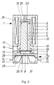
- the solenoid valve 1 shown in Figure 1 has a coil body 2, in which a coil 3 is housed.
- the bobbin 2 has a guide cylinder 4, in which a core 5 is slidably mounted.
- the core 5 has a seal 6 in the manner of a piston.
- the core 5 also carries a valve body 7, which can have a valve plate 8 made of elastic material.
- a valve seat 9 is assigned to the valve body 7 or the valve plate 8 and is designed as a retracted housing edge of the coil body 2.
- the valve seat 9 has a diameter that corresponds to the seal 6.
- a bore 10 passes through the core 5 between its end face 11 on the valve body side and an end face 12 at the other end of the core 5.
- the end faces 11 and 12 are directed in opposite directions.
- the end face 11 is exposed to an active space 13 which is in permanent connection with a connection 14, from which an indicated line 15 branches off to a consumer.
- a line 16 leads from a compressed air source and a compressed air reservoir to a connection 17 on the coil former 2 and to a storage chamber 18.
- a closing spring 19 can be provided in the storage chamber 18. The closing spring 19 could also be arranged elsewhere on the solenoid valve, for example adjacent to the end face 12. It is only important that the force of the closing spring 19 loads the core 5 with the valve body 7 in the closing direction of the valve 8, 9.
- an active space 20 is provided, which is in permanent connection with the active space 13 via the bore 10.
- the core 5 is designed to be pressure-relieved.
- the seal 6 divides the active space 20 from the storage chamber 18 and thus the connections 14 and 17 from one another.
- the solenoid valve according to Figure 1 is shown in the closed position.
- the circuit to the coil 3 is open, and the valve 8, 9 is held in the closed position solely by the closing force of the closing spring 19.
- the supply air present in the supply chamber 18 does not exert any force on the core 5, since the diameter of the seal 6 corresponds to the diameter of the valve seat 9.
- the core 5 When the coil 3 is energized, that is to say the circuit is closed, the core 5 is attracted in the direction of a yoke 21 which bundles the magnetic lines and which advantageously consists of iron or a corresponding insert in the coil body 2 which is otherwise made of plastic. With this movement, only the friction of the seal 6 and the force of the closing spring 19 must be overcome. After opening the valve 8, 9, supply air flows from the supply chamber 18 via the active space 13, the connection 14 and the line 15 to the consumer. A corresponding pressure will also set in the active space 20 via the bore 10, so that the core 5 remains relieved of pressure.
- the closing spring 19 guides the core 5 with the valve body 7 into the closed position.
- the connection of a compressed air supply at connection 17 and that of a consumer at connection 14 is in principle also reversible.
- the solenoid valve shown in Figure 2 is designed as a three / two-way valve.
- a connection 22 is also provided which leads to the atmosphere as a ventilation connection.
- the valve body 7 has an annular valve plate 8 for realizing the inlet valve 8, 9.
- a further valve plate 23 is assigned to a valve seat 24, so that here an outlet valve 23, 24 is formed in addition to the inlet valve 8, 9.
- the valve body 7 is thus a double valve body educated.
- the valve body 7 is either formed directly in one piece with the core 5, the coil body 2 having to be divided accordingly for the purpose of assembly.
- the solenoid valve according to Figure 2 is shown in the non-excited position.
- the core 5 is designed to be pressure-relieved, so that the weak force of the closing spring 19 is able to hold the inlet valve 8, 9 in the closed position.
- the outlet valve 23, 24 is closed and the inlet valve 8, 9 is opened, so that the previously vented consumer is now supplied with compressed air.
- the diameters of the valve plates 8 and 23 or the valve seats 9 and 24 also have the same diameter as the seal 6 of the core 5.
- the embodiment of the solenoid valve according to Figure 3 is initially largely similar to that of Figure 1, which is why reference can be made to the description there.
- the core 5 has in the region of its end face 12 a valve plate 25 made of elastic material, which forms a small cross-sectional outlet valve with a projecting edge 26.
- a quick release valve 27 is provided.
- the quick release valve has a movable valve membrane 28 made of elastic material, which has an overflow lip 29 on its largest diameter. On a smaller diameter, the valve membrane with a projecting housing edge 30 forms a comparatively large cross-sectional vent valve 28, 30. Two lines to consumers can be connected via a distribution space 31.
- the solenoid valve according to Figure 3 is shown in the non-excited position.
- the closing spring 19 keeps the inlet valve 8, 9 closed.
- the consumers are vented.
- the core 5 is shifted, the inlet valve 8, 9 opened and the outlet valve 25, 26 closed. Compressed air thus flows from the storage chamber 18 into the active space 13 and via the overflow lip 29 of the valve membrane 28 to the consumers.
- the consumers are ventilated.
- the circuit to coil 3 is opened.
- the closing spring 19 closes the inlet valve 8, 9 and opens the outlet valve 25, 26. By opening this outlet valve, the outlet valve 28, 30 on the quick-release valve 27 is opened and thus the consumer is quickly vented.
- a further valve seat 32 is provided concentrically and within the valve seat 9 of the inlet valve 8, 9, which also cooperates with the valve plate 8.
- a line 33 is provided which may lead to a consumer on the right side of the vehicle.
- the inlet valve 8, 9 definitely has a closing function.
- the further valve 8, 32 either also has a closing function or a throttle function in order to enable a transverse throttle between the right and left side of the vehicle. If the valve 8, 32 has a closing function, a separate bore 34 can be provided to enable the transverse throttling.
- the effective space 20 leads via a throttle 35 to a pressure sensor 36, which can be designed as a pressure / voltage converter.
- the bore 10 thus has a second function, and it is possible in a simple manner to measure the pressure in line 33 (and in line 15) to the consumers in the upper part of the solenoid valve 1.
- the electrical connections for the coil 3 are also provided in the upper part 37 of the solenoid valve 1.
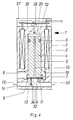
- the embodiment according to FIG. 5 builds on the preceding embodiments of the solenoid valve, in the lower area in particular on the embodiment according to FIG. 4.
- a further valve body 38 is provided in the core 5 which is supported on a spring 39.
- the valve body 38 can be sealingly guided in the core 5; in general, however, this is not necessary.
- the bore 10 passes through not only the core 5, but also the valve body 38.
- the two parts of the bore 10 have a connection to one another via a space 40.
Landscapes
- Engineering & Computer Science (AREA)
- General Engineering & Computer Science (AREA)
- Mechanical Engineering (AREA)
- Physics & Mathematics (AREA)
- Electromagnetism (AREA)
- Fluid Mechanics (AREA)
- Transportation (AREA)
- Magnetically Actuated Valves (AREA)
Abstract
Description
Die Erfindung bezieht sich auf ein Magnetventil mit mindestens zwei Anschlüssen, einer Spule und einem in einem Zylinder der Spule verschiebbar geführten Kern, der mit einem Ventilkörper verbunden ist, der über die Bewegung des Kerns in den Zylinder der Spule gegenüber mindestens einem dem Ventilkörper zugeordneten Ventilsitz steuerbar ist, wobei der Kern druckentlastet ausgebildet und in entgegengesetzte Richtungen weisende Stirnflächen aufweist, die über eine Leitung dauernd in Verbindung stehenden Wirkräumen ausgesetzt sind. Ein solches Magnetventil wird insbesondere in Verbindung mit Druckluftbremsanlagen an Kraftfahrzeugen eingesetzt und dient zumindest dazu, Druckluft aus einem Vorratsanschluß zu einem Verbraucher zu schicken und in der anderen Stellung diesen Verbraucher zu entlüften.The invention relates to a solenoid valve with at least two connections, a coil and a core which is displaceably guided in a cylinder of the coil and which is connected to a valve body, which via the movement of the core in the cylinder of the coil opposite at least one valve seat assigned to the valve body is controllable, the core being designed to be pressure-relieved and having end faces pointing in opposite directions, which are continuously exposed to active spaces connected via a line. Such a solenoid valve is used in particular in connection with compressed air brake systems on motor vehicles and at least serves to send compressed air from a supply connection to a consumer and to vent this consumer in the other position.
Ein Magnetventil der eingangs beschriebenen Art ist aus der DE-AS 25 28 873 bekannt. Das Magnetventil weist eine Spule auf, die in einem Spulenkörper aus Kunststoff gelagert ist. Der Spulenkörper besitzt eine Durchbrechung, in die ein Zylinderrohr eingesetzt ist, welches eine Führung für einen in dem Zylinder verschiebbaren Kern bildet. Der Kern ist mit Spiel in dem Zylinder gelagert. Er kann eine Längsnut aufweisen, die eine Leitung bildet, über die die beiden in entgegengesetzte Richtung weisenden Stirnflächen dauernd miteinander in Verbindung stehen. Den beiden Stirnflächen sind Wirkräume zugeordnet, so daß der Kern des Magnetventils druckentlastet ausgebildet ist. Das Magnetventil stellt insoweit ein aus dem Bereich der Elektrotechnik stammendes Bauteil dar, welches mit einem aus der Ventiltechnik stammenden mechanischen Teil verbunden ist. Zu diesem Zweck ist ein druckentlasteter Steuerkörper vorgesehen, der einen Doppelventilkörper trägt und seinerseits eine Dichtung besitzt, in der er in einem gehäuseartigen Führungsstück gleitend und dichtend gelagert ist. Dem Doppelventilkörper sind zwei Sitze zugeordnet, deren Durchmesser kleiner als der Durchmesser des Kerns ausgebildet ist. Auf den Ventilkörper wirkt eine Feder ein, die den Ventilkörper in Schließrichtung auf den einen Ventilsitz belastet. Über eine Plungerstange ist der Steuerkörper gleichsam an den Kern des Magnetventiles angehängt, so daß der Steuerkörper die Bewegungen des Kerns des Magnetventiles ausführt. Der Steuerkörper besitzt eine Längsbohrung, die im Bereich des Doppelventilkörpers in eine Querbohrung übergeht, über die auch die beiden Wirkräume des Kerns angeschlossen sind. Das Magnetventil besitzt drei Anschlüsse, nämlich einen Anschluß für einen Vorrat, einen zweiten Anschluß für einen Verbraucher und schließlich einen Entlüftungsanschluß. Das Magnetventil ist damit als Drei/Zwei-Wegeventil ausgebildet und dient zur wahlweisen Be- und Entlüftung des Verbrauchers.A solenoid valve of the type described above is known from DE-AS 25 28 873. The solenoid valve has a coil which is mounted in a coil body made of plastic. The coil former has an opening, into which a cylinder tube is inserted, which forms a guide for a core which can be displaced in the cylinder. The core is supported with play in the cylinder. It can have a longitudinal groove which forms a line via which the two end faces pointing in the opposite direction are in permanent communication with one another. Active spaces are assigned to the two end faces, so that the core of the solenoid valve is designed to be depressurized. In this respect, the solenoid valve represents a component originating from the field of electrical engineering, which is connected to a mechanical part originating from valve technology. For this purpose, a pressure-relieved control body is provided, which carries a double valve body and in turn has a seal in which it is slidably and sealingly mounted in a housing-like guide piece. The double valve body is assigned two seats, the diameter of which is smaller than the diameter of the core. A spring acts on the valve body and loads the valve body on the one valve seat in the closing direction. The control body is, as it were, attached to the core of the solenoid valve via a plunger rod, so that the control body executes the movements of the core of the solenoid valve. The control body has a longitudinal bore that merges into a transverse bore in the area of the double valve body, via which the two active spaces of the core are also connected. The solenoid valve has three connections, namely a connection for a supply, a second connection for a consumer and finally a vent connection. The solenoid valve is thus designed as a three / two-way valve and is used for optional ventilation of the consumer.
Andererseits ist aus der DE 35 24 639 C2 ein Magnetventil bekannt, bei dem die Integration zwischen dem elektrischen Teil und dem mechanischen Teil bereits in der Weise weitergeführt worden ist, als der Kern des Magnetventils direkt bereits den Ventilkörper des Sitzventiles bildet bzw. eine Ventilplatte trägt, die mit dem Ventilsitz den entsprechenden mechanischen Ventilteil bildet. Eine Druckentlastung ist durch Anwendung eines besonderen Fortsatzes im Bereich des Druckluftanschlusses erreicht. Über Längsnuten im Umfang des Kerns wird eine Entlüftung des Verbrauchers möglich. Die vom Einlaßsitz in der Offenstellung bereitsgestellte Durchströmfläche besitzt einen typischerweise sehr kleinen Querschnitt, so daß sich relativ hohe Belüftungszeiten ergeben. Der Durchmesser des Ventilsitzes ist erheblich kleiner als der Außendurchmesser des Kerns ausgebildet.On the other hand, a solenoid valve is known from
Weiterhin sind zur Bereitstellung großer Querschnitte Membranventile mit Vorsteuerung bekannt, die einen elektrischen Teil aufweisen, in welchem ein relativ kleiner Querschnitt verwirklicht wird und insoweit die von der Spule des Magnetventils zu überwindenden Kräfte vorteilhaft klein gehalten werden. Es werden dann mit dieser Vorsteuerung größere Ventilflächen beaufschlagt, die den eigentlichen Überströmquerschnitt dann bereitstellen, der vergleichsweise erheblich größer ausgebildet ist. Solche Membranventile mit Vorsteuerung sind jedoch kompliziert, aufwendig und dadurch teuer.Furthermore, to provide large cross-sections, diaphragm valves with pilot control are known which have an electrical part in which a relatively small cross-section is realized and in this respect the forces to be overcome by the coil of the solenoid valve are advantageously kept small. This pilot control then acts on larger valve areas, which then provide the actual overflow cross section, which is comparatively considerably larger. Such diaphragm valves with pilot control are complicated, complex and therefore expensive.
Der Erfindung liegt die Aufgabe zugrunde, ein Magnetventil der eingangs beschriebenen Art bereitzustellen, dessen Kern über eine im normalen Bereich ausgebildete Spule betätigbar ist und die dennoch unter Vermeidung einer Vorsteuerung auf direktem Wege relativ große Überströmquerschnitte zur Verfügung stellt.The invention has for its object to provide a solenoid valve of the type described above, the core of which can be actuated via a coil formed in the normal range and which nevertheless provides relatively large overflow cross sections by avoiding pilot control in a direct way.
Erfindungsgemäß wird dies bei einem Magnetventil der eingangs beschriebenen Art dadurch erreicht, daß der Kern selbst nach Art eines Kolbens mit einer Dichtung versehen ist und damit zwei Anschlußräume abgeteilt sind, daß der Durchmesser des dem Ventilkörper zugeordneten Ventilsitzes dem Durchmesser der Dichtung des Kerns entspricht und daß die durch die Dichtung am Kern getrennten Anschlußräume des Magnetventils an unterschiedliche Anschlüsse angeschlossen sind.According to the invention this is achieved in a solenoid valve of the type described in the introduction that the core itself is provided in the manner of a piston with a seal and thus two connection spaces are divided, that the diameter of the valve seat assigned to the valve body corresponds to the diameter of the seal of the core and that by the seal on Core separate connection spaces of the solenoid valve are connected to different connections.
Die Erfindung geht von dem Gedanken aus, eine weitere Integration herbeizuführen, als dies im Stand der Technik bekannt ist. Dabei wird von einer druckentlasteten Ausbildung des Kerns Gebrauch gemacht, damit dieser Kern in allen Betriebs- und Betätigungszuständen über eine nur vergleichsweise kleine Betätigungskraft über die Spule verschoben werden kann. Die Durchmesser des Ventilsitzes und des Ventilkörpers hingegen werden vergleichsweise groß gewählt, nämlich so groß wie der Durchmesser des Kerns. Der Kern selbst erhält eine Dichtung und wird damit nach Art eines Kolbens ausgebildet, eine Integrationsmaßnahme, die bisher nicht für möglich gehalten wurde, offenbar deshalb, weil eine Fehleinschätzung bestand, den elektrischen Teil und den mechanischen Teil eines solchen Ventils derart eng in Wirkverbindung zu bringen. Geht man aber diesen ungewöhnlichen Schritt der Anordnung einer Dichtung auf dem Kern und macht damit aus dem Kern einen Kolben, dann erhält man gleichzeitig die Möglichkeit, zwei Anschlußräume zu bilden und diese beiden Räume unterschiedlichen Anschlüssen zuzuordnen. Dabei wird die Druckentlastung des Kerns beibehalten. Vorteilhaft ergeben sich relativ große Querschnitte zwischen Ventilkörper und Ventilsitz, wie sie für eine schnelle Be- und Entlüftung unerläßlich sind. Durch die Druckentlastung sind die Betätigungskräfte auf den Kern jedoch vorteilhaft gering; es muß praktisch nur die Reibung der Dichtung und die Kraft einer Schließfeder überwunden werden. Damit ergibt sich überraschenderweise eine geringe Baugröße bei einem relativ großen Überströmquerschnitt. Gegenüber im Stand der Technik vergleichbaren Magnetventilen erhöht sich bei gleichbleibenden äußeren Abmessungen der Durchmesser des Ventilsitzes etwa auf das Vierfache.The invention is based on the idea of bringing about a further integration than is known in the prior art. Use is made of a pressure-relieved design of the core so that this core can be moved over the coil in all operating and actuation states by means of a comparatively small actuation force. The diameters of the valve seat and the valve body, on the other hand, are chosen to be comparatively large, namely as large as the diameter of the core. The core itself receives a seal and is thus designed in the manner of a piston, an integration measure that was previously not thought possible, apparently because there was a misjudgment to bring the electrical part and the mechanical part of such a valve into such close contact . However, if you take this unusual step of arranging a seal on the core and use it to make a piston out of the core, you also have the option of forming two connection spaces and assigning these two spaces to different connections. The pressure relief of the core is maintained. Relatively large cross sections between the valve body and the valve seat, which are essential for rapid ventilation, are advantageous. Due to the pressure relief, the actuating forces on the core are advantageously low; practically only the friction of the seal and the force of a closing spring have to be overcome. This surprisingly results in a small size with a relatively large overflow cross section. Compared to solenoid valves comparable in the prior art, the diameter of the valve seat increases approximately four times with the same external dimensions.
Der druckentlastete Kern mit seinem Ventilkörper kann lediglich von der Kraft einer Schließfeder in Richtung auf den Sitz belastet sein. Statt einer Schließfeder können auch geringfügige Flächenunterschiede in den vergleichbaren Durchmessern zur Anwendung kommen.The pressure-relieved core with its valve body can only be loaded by the force of a closing spring in the direction of the seat. Instead of a closing spring, slight differences in area in the comparable diameters can also be used.
Der Kern mit dem Ventilkörper kann vorteilhaft einstückig oder lediglich aus Montagegründen geteilt ausgebildet sein, um den Kern mit dem Ventilkörper im Spulenkörper montieren zu können.The core with the valve body can advantageously be formed in one piece or only for assembly reasons in order to be able to mount the core with the valve body in the coil body.
Der Ventilkörper des Kerns kann als Doppelventilkörper ausgebildet sein, wobei dem Doppelventilkörper zwei Ventilsitze mit übereinstimmenden Durchmessern zugeordnet sind. Damit ist vorteilhaft ein Drei/Zwei-Wegeventil realisierbar, welches zur Be- und Entlüftung eines Verbrauchers eingesetzt werden kann.The valve body of the core can be designed as a double valve body, two valve seats with matching diameters being assigned to the double valve body. A three / two-way valve can thus advantageously be implemented, which can be used for venting and venting a consumer.
Der Kern kann im Bereich beider Stirnflächen je einen Ventilkörper mit zugeordnetem Ventilsitz aufweisen, wobei dem Einlaßventil ein Schnellöseventil zugeordnet sein kann, um auch die Entlüftung in relativ kurzer Zeit durchführen zu können.The core can each have a valve body with an associated valve seat in the area of both end faces, and a quick-release valve can be associated with the inlet valve in order to be able to carry out the ventilation in a relatively short time.
Der Durchmesser des Kerns und damit der Dichtung kann zur Bereitstellung großer Überströmquerschnitte im Vergleich zum Durchmesser der Spule groß ausgebildet sein. Der Kern benötigt zu seiner Verschiebung nur noch relativ kleine Kräfte, da er selbst druckentlastet ausgebildet ist.The diameter of the core and thus of the seal can be made large in order to provide large overflow cross sections in comparison to the diameter of the coil. The core only needs relatively small forces to move it, since it is itself designed to relieve pressure.
Dem Ventilkörper des Kerns können zwei Ventilsitze zugeordnet sein, die einander konzentrisch umgeben. Zumindest der Sitz mit dem größeren Durchmesser weist Schließfunktion auf. Der Sitz mit dem kleineren Durchmesser kann eine Drosselfunktion erbringen, so daß auf diese Art und Weise zwei Verbraucher, z. B. rechts und links am Fahrzeug anschließbar sind, die letztlich über eine Querdrossel miteinander in Verbindung stehen. Es ist aber auch möglich, daß beide Sitze eine exakte Schließfunktion erbringen.The valve body of the core can be assigned two valve seats which surround one another concentrically. At least the seat with the larger diameter has a locking function. The seat with the smaller diameter can provide a throttle function, so that in this way two consumers, for. B. can be connected to the right and left of the vehicle, which are ultimately connected to each other via a transverse choke. But it is also possible that both seats provide an exact locking function.
Zu diesem Zweck kann im Kern ein weiterer auf einer Feder abgestützter Ventilkörper verschiebbar gelagert sein, der dem Sitz mit dem kleineren Durchmesser zugeordnet ist.For this purpose, a further valve body supported on a spring can be slidably mounted in the core and is assigned to the seat with the smaller diameter.
Der Zylinder zur Führung des Kerns kann direkt im Spulenkörper der Spule vorgesehen sein. Ein Spulenkörperrohr mit einem Führungszylinder für den Kern entfällt. Der Innendurchmesser der Spule ist damit maximal nutzbar zur Realisierung eines vergleichsweise großen Durchmessers des Kerns.The cylinder for guiding the core can be provided directly in the coil body of the coil. A bobbin tube with a guide cylinder for the core is not required. The inner diameter of the coil can thus be used to the maximum for realizing a comparatively large diameter of the core.
Als Leitung zur Verbindung der beiden Wirkräume kann eine den Kern axial durchsetzende Bohrung vorgesehen sein. Trotz dieser Bohrung muß natürlich die Dichtung am Kern weiterhin realisiert werden.A bore axially penetrating the core can be provided as a line for connecting the two active spaces. Despite this hole, the seal on the core must of course still be implemented.
Die Erfindung wird anhand bevorzugter Ausführungsbeispiele weiter erläutert und beschrieben. Es zeigen:
Figur 1- einen schematisierten Schnitt durch die wesentlichen Teile eines Magnetventils als Zwei/Zwei-Wegeventil,
Figur 2- einen Schnitt durch das Magnetventil in einer zweiten Ausführungsform mit einem Doppelventilkörper, z. B. als Drei/Zwei-Wegeventil,
Figur 3- einen Schnitt durch eine dritte Ausführungsform des Magnetventils mit einem eigenen Entlüftungsventil und einem Schnellöseventil,
Figur 4- einen Schnitt durch eine weitere Ausführungsform des Magnetventils mit zwei konzentrischen Ventilsitzen und
Figur 5- eine Weiterbildung des Magnetventils gemäß
Figur 4.
- Figure 1
- a schematic section through the essential parts of a solenoid valve as a two / two-way valve,
- Figure 2
- a section through the solenoid valve in a second embodiment with a double valve body, for. B. as a three / two-way valve,
- Figure 3
- FIG. 2 shows a section through a third embodiment of the solenoid valve with its own vent valve and a quick release valve,
- Figure 4
- a section through a further embodiment of the solenoid valve with two concentric valve seats and
- Figure 5
- a development of the solenoid valve according to FIG. 4.
Das in Figur 1 dargestellte Magnetventil 1 weist einen Spulenkörper 2 auf, in dem eine Spule 3 untergebracht ist. Der Spulenkörper 2 besitzt einen Führungszylinder 4, in welchem direkt ein Kern 5 gleitend gelagert ist. Der Kern 5 weist nach Art eines Kolbens eine Dichtung 6 auf. Der Kern 5 trägt darüberhinaus einen Ventilkörper 7, der eine Ventilplatte 8 aus elastischem Material aufweisen kann. Dem Ventilkörper 7 bzw. der Ventilplatte 8 ist ein Ventilsitz 9 zugeordnet, der als eingezogener Gehäuserand des Spulenkörpers 2 ausgebildet ist. Der Ventilsitz 9 weist einen mit der Dichtung 6 übereinstimmenden Durchmesser auf. Eine Bohrung 10 durchsetzt den Kern 5 zwischen seiner ventilkörperseitigen Stirnfläche 11 und einer Stirnfläche 12 am anderen Ende des Kerns 5. Die Stirnflächen 11 und 12 sind einander entgegengesetzt gerichtet. Die Stirnfläche 11 ist einem Wirkraum 13 ausgesetzt, der in dauernder Verbindung zu einem Anschluß 14 steht, von dem eine angedeutete Leitung 15 zu einem Verbraucher abzweigt. Eine Leitung 16 führt von einer Druckluftquelle und einem Druckluftvorratsbehälter zu einem Anschluß 17 am Spulenkörper 2 und zu einer Vorratskammer 18. In der Vorratskammer 18 kann eine Schließfeder 19 vorgesehen sein. Die Schließfeder 19 könnte auch an anderer Stelle des Magnetventils angeordnet sein, beispielsweise benachbart zu der Stirnfläche 12. Wichtig ist nur, daß die Kraft der Schließfeder 19 den Kern 5 mit dem Ventilkörper 7 in Schließrichtung des Ventiles 8, 9 belastet.The
Im Anschluß an die Stirnfläche 12 ist ein Wirkraum 20 vorgesehen, der über die Bohrung 10 in dauernder Verbindung zu dem Wirkraum 13 steht. Insoweit ist der Kern 5 druckentlastet ausgebildet. Über die Bohrung 10 besteht auch Verbindung zwischen dem Anschluß 14 und dem Wirkraum 20. Andererseits unterteilt die Dichtung 6 den Wirkraum 20 von der Vorratskammer 18 und damit die Anschlüsse 14 und 17 voneinander.Following the
Das Magnetventil gemäß Figur 1 ist in der Schließstellung dargestellt. Der Stromkreis zu der Spule 3 ist geöffnet, und das Ventil 8, 9 wird allein durch die Schließkraft der Schließfeder 19 in der geschlossenen Stellung gehalten. Die in der Vorratskammer 18 anstehende Vorratsluft übt keine Kraft auf den Kern 5 aus, da der Durchmesser der Dichtung 6 mit dem Durchmesser des Ventilsitzes 9 übereinstimmt.The solenoid valve according to Figure 1 is shown in the closed position. The circuit to the
Wenn die Spule 3 erregt, also der Stromkreis geschlossen wird, wird der Kern 5 in Richtung auf ein die Magnetlinien bündelndes Joch 21, welches zweckmäßig aus Eisen besteht oder einen entsprechenden Einsatz im ansonsten aus Kunststoff bestehenden Spulenkörper 2 darstellt, angezogen. Bei dieser Bewegung muß lediglich die Reibung der Dichtung 6 sowie die Kraft der Schließfeder 19 überwunden werden. Nach dem Öffnen des Ventiles 8, 9 strömt Vorratsluft aus der Vorratskammer 18 über den Wirkraum 13, den Anschluß 14 und die Leitung 15 zum Verbraucher. Über die Bohrung 10 wird sich auch im Wirkraum 20 ein entsprechender Druck einstellen, so daß der Kern 5 weiterhin druckentlastet bleibt.When the
Wird andererseits der Stromkreis geöffnet, dann führt die Schließfeder 19 den Kern 5 mit dem Ventilkörper 7 in die Schließstellung. Der Anschluß eines Druckluftvorrates am Anschluß 17 und der eines Verbrauchers am Anschluß 14 ist grundsätzlich auch umkehrbar.If, on the other hand, the circuit is opened, the closing
Das in Figur 2 dargestellte Magnetventil ist als Drei/Zwei-Wegeventil ausgebildet. Neben den Anschlüssen 17 für Vorratsluft und 14 für eine zu einem Verbraucher 15 führende Leitung ist noch ein Anschluß 22 vorgesehen, der als Entlüftungsanschluß in die Atmosphäre führt. Der Ventilkörper 7 besitzt eine ringförmige Ventilplatte 8 zur Realisierung des Einlaßventiles 8, 9. Eine weitere Ventilplatte 23 ist einem Ventilsitz 24 zugeordnet, so daß hier neben dem Einlaßventil 8, 9 ein Auslaßventil 23, 24 gebildet ist. Der Ventilkörper 7 ist damit als Doppelventilkörper ausgebildet. Auch hier ist der Ventilkörper 7 entweder direkt einstückig mit dem Kern 5 ausgebildet, wobei zum Zwecke der Montage der Spulenkörper 2 entsprechend unterteilt sein müßte. Andererseits ist es auch möglich, den Kern 5 mit seinem im Bereich der Spule 3 befindlichen Teil einerseits und seinem den Ventilkörper 7 bildenden anderen Teil zweiteilig auszubilden und miteinander dichtend zu verschrauben.The solenoid valve shown in Figure 2 is designed as a three / two-way valve. In addition to the
Das Magnetventil gemäß Figur 2 ist in der nicht-erregten Stellung dargestellt. Auch hier ist der Kern 5 druckentlastet ausgebildet, so daß die schwache Kraft der Schließfeder 19 in der Lage ist, das Einlaßventil 8, 9 in der Schließstellung zu halten. Bei Erregung der Spule 3 wird das Auslaßventil 23, 24 geschlossen und das Einlaßventil 8, 9 geöffnet, so daß der vorher entlüftete Verbraucher nunmehr mit Druckluft versorgt wird. Es ist erkennbar, daß auch hier die Durchmesser der Ventilplatten 8 und 23 bzw. der Ventilsitze 9 und 24 gleichen Durchmesser wie die Dichtung 6 des Kerns 5 aufweisen.The solenoid valve according to Figure 2 is shown in the non-excited position. Here, too, the
Die Ausführungsform des Magnetventils gemäß Figur 3 ist zunächst weitgehend ähnlich zu der gemäß Figur 1 aufgebaut, weshalb auf die dortige Beschreibung verwiesen werden kann. Zusätzlich weist der Kern 5 im Bereich seiner Stirnfläche 12 eine Ventilplatte 25 aus elastischem Material auf, die mit einem vorstehenden Rand 26 ein kleinquerschnittiges Auslaßventil bildet. Zusätzlich ist ein Schnellöseventil 27 vorgesehen. Das Schnellöseventil weist eine bewegliche Ventilmembran 28 aus elastischem Material auf, die auf ihrem größten Durchmesser eine Überströmlippe 29 trägt. Auf einem kleineren Durchmesser bildet die Ventilmembran mit einem vorspringenden Gehäuserand 30 ein vergleichsweise großquerschnittiges Entlüftungsventil 28, 30. Über einen Verteilungsraum 31 können zwei Leitungen zu Verbrauchern angeschlossen sein.The embodiment of the solenoid valve according to Figure 3 is initially largely similar to that of Figure 1, which is why reference can be made to the description there. In addition, the
Das Magnetventil gemäß Figur 3 ist in der nicht-erregten Stellung dargestellt. Die Schließfeder 19 hält das Einlaßventil 8, 9 geschlossen. Die Verbraucher sind entlüftet. Bei Erregung der Spule 3 wird der Kern 5 verschoben, das Einlaßventil 8, 9 geöffnet und das Auslaßventil 25, 26 geschlossen. Damit strömt Druckluft aus der Vorratskammer 18 in den Wirkraum 13 und über die Überströmlippe 29 der Ventilmembran 28 zu den Verbrauchern. Die Verbraucher werden belüftet. Zum Zwecke der Entlüftung wird der Stromkreis zur Spule 3 geöffnet. Die Schließfeder 19 schließt das Einlaßventil 8, 9 und öffnet das Auslaßventil 25, 26. Durch die Öffnung dieses Auslaßventils wird das Auslaßventil 28, 30 am Schnellöseventil 27 geöffnet und damit die Verbraucher schnell entlüftet.The solenoid valve according to Figure 3 is shown in the non-excited position. The closing
Die Besonderheit des Magnetventils 1 gemäß Figur 4 besteht darin, daß konzentrisch und innerhalb des Ventilsitzes 9 des Einlaßventiles 8, 9 ein weiterer Ventilsitz 32 vorgesehen ist, der mit der Ventilplatte 8 ebenfalls zusammenarbeitet. Neben der Leitung 15 zu einem Verbraucher, beispielsweise auf der linken Fahrzeugseite, ist eine Leitung 33 vorgesehen, die zu einem Verbraucher auf der rechten Fahrzeugseite führen möge. Das Einlaßventil 8, 9 besitzt auf jeden Fall Schließfunktion. Das weitere Ventil 8, 32 besitzt entweder ebenfalls Schließfunktion oder aber Drosselfunktion, um eine Querdrossel zwischen der rechten und linken Fahrzeugseite zu ermöglichen. Falls das Ventil 8, 32 Schließfunktion besitzt, kann eine gesonderte Bohrung 34 vorgesehen sein, um die Querdrosselung zu ermöglichen.The special feature of the
Eine weitere Besonderheit des Magnetventils gemäß Figur 4 besteht darin, daß der Wirkraum 20 über eine Drossel 35 zu einem Drucksensor 36 führt, der als Druck/Spannungs-Umwandler ausgebildet sein kann. Damit erhält die Bohrung 10 eine zweite Funktion, und es ist in einfacher Weise möglich, im Oberteil des Magnetventiles 1 den Druck in der Leitung 33 (und in der Leitung 15) zu den Verbrauchern zu messen. Im Oberteil 37 des Magnetventils 1 sind auch die elektrischen Anschlüsse für die Spule 3 vorgesehen.Another special feature of the solenoid valve according to FIG. 4 is that the
Die Ausführungsform gemäß Figur 5 baut auf den vorangehenden Ausführungsformen des Magnetventiles auf, im unteren Bereich insbesondere auf der Ausführungsform gemäß Figur 4. Um in Verbindung mit dem Ventilsitz 32 jedoch mit Sicherheit eine Schließfunktion zu erreichen, ist in dem Kern 5 ein weiterer Ventilkörper 38 vorgesehen, der auf einer Feder 39 abgestützt ist. Der Ventilkörper 38 kann in dem Kern 5 dichtend geführt sein; im allgemeinen ist dies jedoch nicht erforderlich. Die Bohrung 10 durchsetzt nicht nur den Kern 5, sondern auch den Ventilkörper 38. Die beiden Teile der Bohrung 10 haben über einen Raum 40 untereinander Anschluß.The embodiment according to FIG. 5 builds on the preceding embodiments of the solenoid valve, in the lower area in particular on the embodiment according to FIG. 4. In order to achieve a closing function with certainty in connection with the
- 11
- - Magnetventil- Magnetic valve
- 22nd
- - Spulenkörper- bobbin
- 33rd
- - Spule- Kitchen sink
- 44th
- - Führungszylinder- guide cylinder
- 55
- - Kern- Core
- 66
- - Dichtung- Poetry
- 77
- - Ventilkörper- valve body
- 88th
- - Ventilplatte- valve plate
- 99
- - Ventilsitz- valve seat
- 1010th
- - Bohrung- Drilling
- 1111
- - Stirnfläche- face
- 1212th
- - Stirnfläche- face
- 1313
- - Wirkraum- effective space
- 1414
- - Anschluß- connection
- 1515
- - Leitung- Management
- 1616
- - Leitung- Management
- 1717th
- - Anschluß- connection
- 1818th
- - Vorratskammer- pantry
- 1919th
- - Schließfeder- closing spring
- 2020th
- - Wirkraum- effective space
- 2121
- - Joch- Yoke
- 2222
- - Anschluß- connection
- 2323
- - Ventilplatte- valve plate
- 2424th
- - Ventilsitz- valve seat
- 2525th
- - Ventilplatte- valve plate
- 2626
- - Rand- Edge
- 2727
- - Schnellöseventil- Quick release valve
- 2828
- - Ventilmembran- valve membrane
- 2929
- - Überströmlippe- Overflow lip
- 3030th
- - Gehäuserand- Housing edge
- 3131
- - Verteilungsraum- Distribution room
- 3232
- - Ventilsitz- valve seat
- 3333
- - Leitung- Management
- 3434
- - Bohrung- Drilling
- 3535
- - Drossel- throttle
- 3636
- - Drucksensor- pressure sensor
- 3737
- - Oberteil- top
- 3838
- - Ventilkörper- valve body
- 3939
- - Feder- Feather
- 4040
- - Raum- space
Claims (10)
Applications Claiming Priority (2)
| Application Number | Priority Date | Filing Date | Title |
|---|---|---|---|
| DE4416279A DE4416279A1 (en) | 1994-05-07 | 1994-05-07 | magnetic valve |
| DE4416279 | 1994-05-07 |
Publications (2)
| Publication Number | Publication Date |
|---|---|
| EP0681128A1 true EP0681128A1 (en) | 1995-11-08 |
| EP0681128B1 EP0681128B1 (en) | 1998-07-08 |
Family
ID=6517643
Family Applications (1)
| Application Number | Title | Priority Date | Filing Date |
|---|---|---|---|
| EP95106611A Expired - Lifetime EP0681128B1 (en) | 1994-05-07 | 1995-05-03 | Solenoid valve |
Country Status (3)
| Country | Link |
|---|---|
| EP (1) | EP0681128B1 (en) |
| DE (2) | DE4416279A1 (en) |
| ES (1) | ES2120659T3 (en) |
Cited By (15)
| Publication number | Priority date | Publication date | Assignee | Title |
|---|---|---|---|---|
| EP0872674A1 (en) | 1997-04-14 | 1998-10-21 | Bürkert Gmbh & Co. | Pressure-compensated solenoid valve |
| WO1999010213A1 (en) * | 1997-08-22 | 1999-03-04 | Alliedsignal Inc. | Abs modulator solenoid with a pressure balancing piston |
| EP0864794A3 (en) * | 1997-03-14 | 1999-06-16 | FLUTEC Fluidtechnische Geräte GmbH | Proportional throttle valve |
| EP1077340A3 (en) * | 1999-08-19 | 2002-07-31 | Parker-Hannifin Corporation | Solenoid valve plunger |
| EP1128106A3 (en) * | 2000-02-26 | 2002-08-14 | WABCO GmbH & CO. OHG | Valve device for a pilot unit of a brake pressure modulator |
| EP1319566A3 (en) * | 2001-12-14 | 2003-10-29 | WABCO GmbH & CO. OHG | Solenoid and pressure sensor unit |
| EP1353103A3 (en) * | 2002-04-08 | 2003-12-10 | Hygrama Ag | Valve device with electromagnetic actuation |
| WO2004044468A1 (en) * | 2003-02-26 | 2004-05-27 | Teknocraft, Inc. | Proportional solenoid-controlled fluid valve having compact pressure-balancing armature-poppet assembly |
| EP1508731A1 (en) * | 2003-08-20 | 2005-02-23 | Eaton Corporation | Electric fluid servo valve and method of making same |
| WO2006038105A1 (en) * | 2004-10-07 | 2006-04-13 | Eaton Corporation | Electromagnetic valve with integral pressure sensor |
| US7028978B2 (en) | 1996-04-15 | 2006-04-18 | Kumar Viraraghavan S | Proportional solenoid-controlled fluid valve having compact pressure-balancing armature-poppet assembly |
| WO2007039504A1 (en) * | 2005-10-06 | 2007-04-12 | Robert Bosch Gmbh | Hydraulic unit pertaining to a hydraulic vehicle brake device and comprising a pressure sensor |
| WO2014060009A1 (en) * | 2012-10-20 | 2014-04-24 | Festo Ag & Co. Kg | Electrically actuatable valve |
| EP3067599A1 (en) * | 2015-03-09 | 2016-09-14 | FESTO AG & Co. KG | Valve |
| CN108758063A (en) * | 2018-07-31 | 2018-11-06 | 宁波索诺工业自控设备有限公司 | A kind of slow-start solenoid valve |
Families Citing this family (15)
| Publication number | Priority date | Publication date | Assignee | Title |
|---|---|---|---|---|
| DE19530260C2 (en) * | 1995-08-17 | 1998-10-08 | Grau Gmbh | Air suspension system for vehicles |
| DE19546324C2 (en) * | 1995-12-12 | 1998-10-29 | Grau Gmbh | Control block for an air suspension system |
| DE19626288C2 (en) * | 1996-07-01 | 1999-10-21 | Haldex Brake Prod Gmbh & Co Kg | Brake device for an ABS system |
| DE19810241C2 (en) * | 1998-03-10 | 2001-07-05 | Bosch Gmbh Robert | Electromagnetic directional control valve |
| DE19836865C1 (en) * | 1998-08-14 | 1999-11-25 | Haldex Brake Prod Gmbh & Co Kg | Magnetic valve for motor vehicle pneumatic brake |
| DE10161497A1 (en) * | 2001-12-14 | 2003-06-26 | Wabco Gmbh & Co Ohg | Solenoid coil pressure sensor unit for EBS modulators of electronically controlled electro-pneumatic brake systems equipped with solenoid control valves |
| DE10163929A1 (en) | 2001-12-22 | 2003-07-03 | Obrist Engineering Gmbh Lusten | needle valve |
| DE10232554B4 (en) * | 2002-07-18 | 2004-05-19 | Haldex Brake Products Gmbh | Solenoid valve for commercial vehicles with air suspension |
| JP4403932B2 (en) * | 2004-09-14 | 2010-01-27 | 株式会社デンソー | Mounting structure of solenoid valve integrated pressure sensor |
| DE102004049542B4 (en) | 2004-10-12 | 2007-07-12 | Haldex Brake Products Gmbh | Control device for an air suspension system for a motor vehicle |
| DE102005022693A1 (en) | 2005-05-18 | 2006-11-23 | Hydac Fluidtechnik Gmbh | Valve, in particular proportional pressure relief valve |
| CN100476274C (en) * | 2006-01-11 | 2009-04-08 | 浙江三花股份有限公司 | Straight moving type three-way electromagnetic valve |
| DE102007005915B3 (en) * | 2007-02-01 | 2008-08-28 | Kendrion Binder Magnete Gmbh | Solenoid valve, has sealing device opening or closing valve openings based on movement of anchor, and support unit provided at anchor or valve seat body, where support unit prevents tilting of anchor |
| DE102008006380A1 (en) | 2008-01-29 | 2009-07-30 | Hydac Fluidtechnik Gmbh | Pilot operated valve, in particular proportional throttle valve |
| DE102019130523A1 (en) | 2019-11-12 | 2021-05-12 | Nass Magnet Gmbh | Pneumatic valve device for a compressed air device and transmission control or clutch system with the pneumatic valve device |
Citations (5)
| Publication number | Priority date | Publication date | Assignee | Title |
|---|---|---|---|---|
| US3011753A (en) * | 1960-07-08 | 1961-12-05 | Airmatic Valve Inc | Flow control valve |
| DE2528873A1 (en) * | 1974-06-28 | 1976-01-15 | Gen Signal Corp | FAST RESPONSE VALVE |
| FR2565660A1 (en) * | 1985-08-12 | 1985-12-13 | Target Rock Corp | ANTICAVITATION VALVE ASSEMBLY |
| EP0380754A2 (en) * | 1989-01-28 | 1990-08-08 | KUHNKE GmbH | Force-balanced lift valve |
| DE3524639C2 (en) * | 1984-12-03 | 1992-01-02 | William Joseph Farmington Mich. Us Chorkey |
Family Cites Families (2)
| Publication number | Priority date | Publication date | Assignee | Title |
|---|---|---|---|---|
| DE3345928A1 (en) * | 1983-12-20 | 1985-06-27 | Wabco Westinghouse Fahrzeugbremsen GmbH, 3000 Hannover | Magnetic valve |
| DE9203413U1 (en) * | 1992-03-13 | 1992-06-04 | H. Kuhnke Gmbh Kg, 2427 Malente | Force balanced valve |
-
1994
- 1994-05-07 DE DE4416279A patent/DE4416279A1/en not_active Withdrawn
-
1995
- 1995-05-03 ES ES95106611T patent/ES2120659T3/en not_active Expired - Lifetime
- 1995-05-03 EP EP95106611A patent/EP0681128B1/en not_active Expired - Lifetime
- 1995-05-03 DE DE59502726T patent/DE59502726D1/en not_active Expired - Fee Related
Patent Citations (5)
| Publication number | Priority date | Publication date | Assignee | Title |
|---|---|---|---|---|
| US3011753A (en) * | 1960-07-08 | 1961-12-05 | Airmatic Valve Inc | Flow control valve |
| DE2528873A1 (en) * | 1974-06-28 | 1976-01-15 | Gen Signal Corp | FAST RESPONSE VALVE |
| DE3524639C2 (en) * | 1984-12-03 | 1992-01-02 | William Joseph Farmington Mich. Us Chorkey | |
| FR2565660A1 (en) * | 1985-08-12 | 1985-12-13 | Target Rock Corp | ANTICAVITATION VALVE ASSEMBLY |
| EP0380754A2 (en) * | 1989-01-28 | 1990-08-08 | KUHNKE GmbH | Force-balanced lift valve |
Cited By (20)
| Publication number | Priority date | Publication date | Assignee | Title |
|---|---|---|---|---|
| US7028978B2 (en) | 1996-04-15 | 2006-04-18 | Kumar Viraraghavan S | Proportional solenoid-controlled fluid valve having compact pressure-balancing armature-poppet assembly |
| EP0864794A3 (en) * | 1997-03-14 | 1999-06-16 | FLUTEC Fluidtechnische Geräte GmbH | Proportional throttle valve |
| WO1998046919A1 (en) * | 1997-04-14 | 1998-10-22 | Bürkert Werke GmbH & Co. | Wide-ranging valve |
| US6443420B1 (en) | 1997-04-14 | 2002-09-03 | Burkert Werke Gmbh & Co. | Wide-ranging valve |
| EP0872674A1 (en) | 1997-04-14 | 1998-10-21 | Bürkert Gmbh & Co. | Pressure-compensated solenoid valve |
| WO1999010213A1 (en) * | 1997-08-22 | 1999-03-04 | Alliedsignal Inc. | Abs modulator solenoid with a pressure balancing piston |
| EP1077340A3 (en) * | 1999-08-19 | 2002-07-31 | Parker-Hannifin Corporation | Solenoid valve plunger |
| EP1128106A3 (en) * | 2000-02-26 | 2002-08-14 | WABCO GmbH & CO. OHG | Valve device for a pilot unit of a brake pressure modulator |
| EP1319566A3 (en) * | 2001-12-14 | 2003-10-29 | WABCO GmbH & CO. OHG | Solenoid and pressure sensor unit |
| EP1353103A3 (en) * | 2002-04-08 | 2003-12-10 | Hygrama Ag | Valve device with electromagnetic actuation |
| WO2004044468A1 (en) * | 2003-02-26 | 2004-05-27 | Teknocraft, Inc. | Proportional solenoid-controlled fluid valve having compact pressure-balancing armature-poppet assembly |
| EP1508731A1 (en) * | 2003-08-20 | 2005-02-23 | Eaton Corporation | Electric fluid servo valve and method of making same |
| US7798174B2 (en) | 2003-08-20 | 2010-09-21 | Eaton Corporation | Electric fluid servo valve and method of making same |
| WO2006038105A1 (en) * | 2004-10-07 | 2006-04-13 | Eaton Corporation | Electromagnetic valve with integral pressure sensor |
| US7383851B2 (en) | 2004-10-07 | 2008-06-10 | Eaton Corporation | Closed loop pressure control system and electrically operated pressure control valve with integral pressure sensor and method of making same |
| WO2007039504A1 (en) * | 2005-10-06 | 2007-04-12 | Robert Bosch Gmbh | Hydraulic unit pertaining to a hydraulic vehicle brake device and comprising a pressure sensor |
| WO2014060009A1 (en) * | 2012-10-20 | 2014-04-24 | Festo Ag & Co. Kg | Electrically actuatable valve |
| EP3067599A1 (en) * | 2015-03-09 | 2016-09-14 | FESTO AG & Co. KG | Valve |
| CN105952931A (en) * | 2015-03-09 | 2016-09-21 | 费斯托股份有限两合公司 | Valve |
| CN108758063A (en) * | 2018-07-31 | 2018-11-06 | 宁波索诺工业自控设备有限公司 | A kind of slow-start solenoid valve |
Also Published As
| Publication number | Publication date |
|---|---|
| EP0681128B1 (en) | 1998-07-08 |
| DE59502726D1 (en) | 1998-08-13 |
| DE4416279A1 (en) | 1995-11-16 |
| ES2120659T3 (en) | 1998-11-01 |
Similar Documents
| Publication | Publication Date | Title |
|---|---|---|
| EP0681128A1 (en) | Solenoid valve | |
| DE3934771C1 (en) | ||
| EP0400395B1 (en) | Shock absorber | |
| DE60223341T2 (en) | Directly driven pneumatic valve with air-assisted return stroke | |
| EP2004428B1 (en) | On-off valve | |
| DE69111628T2 (en) | Pressure regulator for fluids. | |
| DE102017213736B3 (en) | Pneumatic valve | |
| WO2010085991A2 (en) | Proportional pressure control valve | |
| EP0864794A2 (en) | Proportional throttle valve | |
| DE3305092C2 (en) | ||
| EP1860009A2 (en) | Balanced valve | |
| DE4317706C2 (en) | Power-operated directional seat valve | |
| DE2855902A1 (en) | ELECTROMAGNETICALLY OPERABLE 3/2-WAY VALVE, ESPECIALLY FOR REMOTE CONTROLLING OF UNIT SIDED DEVICES | |
| DE2431135B2 (en) | ||
| EP0182053B1 (en) | Pressure control valve with electromagnetic control | |
| DE19713313B4 (en) | Controllable valve device | |
| DE3439086A1 (en) | RELAY VALVE DEVICE | |
| DE102016220684A1 (en) | Adjustment device for a valve | |
| DE2361591A1 (en) | SLIDER VALVE FOR CONTROLLING THE WORKING PRESSURE OF A WORKING MEDIUM | |
| DE3922566A1 (en) | AT LEAST ONE-CIRCUITABLE RELAY VALVE TO BE USED AS A TRAILER CONTROL OR TRAILER BRAKE VALVE, ESPECIALLY FOR COMPRESSED AIR BRAKE SYSTEMS ON MOTOR VEHICLES | |
| DE2712491A1 (en) | DEVICE FOR SIGNAL CONVERSION | |
| DE3240274A1 (en) | Multi-circuit pressure-medium brake system II | |
| DE19944808C1 (en) | Pressure relief and pressure relief valve for air brake systems of motor vehicles | |
| DE2929578A1 (en) | Pneumatic control system emergency valve - has selector member positions changed by impulse or manual control | |
| DE4125815C2 (en) | Valve, in particular pneumatic switching, continuous, pilot valve u. the like |
Legal Events
| Date | Code | Title | Description |
|---|---|---|---|
| PUAI | Public reference made under article 153(3) epc to a published international application that has entered the european phase |
Free format text: ORIGINAL CODE: 0009012 |
|
| AK | Designated contracting states |
Kind code of ref document: A1 Designated state(s): DE ES FR GB IT |
|
| 17P | Request for examination filed |
Effective date: 19950921 |
|
| 17Q | First examination report despatched |
Effective date: 19970402 |
|
| GRAG | Despatch of communication of intention to grant |
Free format text: ORIGINAL CODE: EPIDOS AGRA |
|
| GRAG | Despatch of communication of intention to grant |
Free format text: ORIGINAL CODE: EPIDOS AGRA |
|
| GRAH | Despatch of communication of intention to grant a patent |
Free format text: ORIGINAL CODE: EPIDOS IGRA |
|
| GRAH | Despatch of communication of intention to grant a patent |
Free format text: ORIGINAL CODE: EPIDOS IGRA |
|
| ITF | It: translation for a ep patent filed | ||
| GRAA | (expected) grant |
Free format text: ORIGINAL CODE: 0009210 |
|
| AK | Designated contracting states |
Kind code of ref document: B1 Designated state(s): DE ES FR GB IT |
|
| GBT | Gb: translation of ep patent filed (gb section 77(6)(a)/1977) |
Effective date: 19980710 |
|
| REF | Corresponds to: |
Ref document number: 59502726 Country of ref document: DE Date of ref document: 19980813 |
|
| ET | Fr: translation filed | ||
| REG | Reference to a national code |
Ref country code: ES Ref legal event code: FG2A Ref document number: 2120659 Country of ref document: ES Kind code of ref document: T3 |
|
| PLBE | No opposition filed within time limit |
Free format text: ORIGINAL CODE: 0009261 |
|
| STAA | Information on the status of an ep patent application or granted ep patent |
Free format text: STATUS: NO OPPOSITION FILED WITHIN TIME LIMIT |
|
| 26N | No opposition filed | ||
| REG | Reference to a national code |
Ref country code: GB Ref legal event code: IF02 |
|
| REG | Reference to a national code |
Ref country code: FR Ref legal event code: TP Ref country code: FR Ref legal event code: CD |
|
| REG | Reference to a national code |
Ref country code: GB Ref legal event code: 732E |
|
| PGFP | Annual fee paid to national office [announced via postgrant information from national office to epo] |
Ref country code: GB Payment date: 20040419 Year of fee payment: 10 |
|
| PGFP | Annual fee paid to national office [announced via postgrant information from national office to epo] |
Ref country code: ES Payment date: 20040524 Year of fee payment: 10 |
|
| PG25 | Lapsed in a contracting state [announced via postgrant information from national office to epo] |
Ref country code: IT Free format text: LAPSE BECAUSE OF NON-PAYMENT OF DUE FEES;WARNING: LAPSES OF ITALIAN PATENTS WITH EFFECTIVE DATE BEFORE 2007 MAY HAVE OCCURRED AT ANY TIME BEFORE 2007. THE CORRECT EFFECTIVE DATE MAY BE DIFFERENT FROM THE ONE RECORDED. Effective date: 20050503 Ref country code: GB Free format text: LAPSE BECAUSE OF NON-PAYMENT OF DUE FEES Effective date: 20050503 |
|
| PG25 | Lapsed in a contracting state [announced via postgrant information from national office to epo] |
Ref country code: ES Free format text: LAPSE BECAUSE OF NON-PAYMENT OF DUE FEES Effective date: 20050504 |
|
| GBPC | Gb: european patent ceased through non-payment of renewal fee |
Effective date: 20050503 |
|
| REG | Reference to a national code |
Ref country code: ES Ref legal event code: FD2A Effective date: 20050504 |
|
| PGFP | Annual fee paid to national office [announced via postgrant information from national office to epo] |
Ref country code: FR Payment date: 20090519 Year of fee payment: 15 Ref country code: DE Payment date: 20090512 Year of fee payment: 15 |
|
| REG | Reference to a national code |
Ref country code: FR Ref legal event code: ST Effective date: 20110131 |
|
| PG25 | Lapsed in a contracting state [announced via postgrant information from national office to epo] |
Ref country code: DE Free format text: LAPSE BECAUSE OF NON-PAYMENT OF DUE FEES Effective date: 20101201 |
|
| PG25 | Lapsed in a contracting state [announced via postgrant information from national office to epo] |
Ref country code: FR Free format text: LAPSE BECAUSE OF NON-PAYMENT OF DUE FEES Effective date: 20100531 |