EP0471675B1 - Abfahrtsski mit integrierter sondeneinheit - Google Patents
Abfahrtsski mit integrierter sondeneinheit Download PDFInfo
- Publication number
- EP0471675B1 EP0471675B1 EP90904529A EP90904529A EP0471675B1 EP 0471675 B1 EP0471675 B1 EP 0471675B1 EP 90904529 A EP90904529 A EP 90904529A EP 90904529 A EP90904529 A EP 90904529A EP 0471675 B1 EP0471675 B1 EP 0471675B1
- Authority
- EP
- European Patent Office
- Prior art keywords
- ski
- probe
- snow
- skier
- probes
- Prior art date
- Legal status (The legal status is an assumption and is not a legal conclusion. Google has not performed a legal analysis and makes no representation as to the accuracy of the status listed.)
- Expired - Lifetime
Links
- 239000000523 sample Substances 0.000 title claims abstract description 200
- 230000033001 locomotion Effects 0.000 claims abstract description 17
- 230000035515 penetration Effects 0.000 claims abstract description 16
- 230000000694 effects Effects 0.000 claims description 12
- 230000005484 gravity Effects 0.000 abstract description 18
- 238000000034 method Methods 0.000 abstract description 11
- 238000004519 manufacturing process Methods 0.000 abstract description 9
- 230000008901 benefit Effects 0.000 description 11
- 230000007246 mechanism Effects 0.000 description 9
- 230000006870 function Effects 0.000 description 7
- 239000000463 material Substances 0.000 description 7
- 210000003205 muscle Anatomy 0.000 description 7
- 239000000945 filler Substances 0.000 description 6
- 206010050031 Muscle strain Diseases 0.000 description 5
- 230000006835 compression Effects 0.000 description 5
- 238000007906 compression Methods 0.000 description 5
- 230000006378 damage Effects 0.000 description 5
- 229910000838 Al alloy Inorganic materials 0.000 description 4
- 208000027418 Wounds and injury Diseases 0.000 description 4
- 238000006073 displacement reaction Methods 0.000 description 4
- 208000014674 injury Diseases 0.000 description 4
- 238000012360 testing method Methods 0.000 description 4
- 241000909536 Gobiesocidae Species 0.000 description 3
- 230000027455 binding Effects 0.000 description 3
- 238000009739 binding Methods 0.000 description 3
- 230000008859 change Effects 0.000 description 3
- 230000009194 climbing Effects 0.000 description 3
- 230000007423 decrease Effects 0.000 description 3
- 210000003127 knee Anatomy 0.000 description 3
- 238000005381 potential energy Methods 0.000 description 3
- 230000001133 acceleration Effects 0.000 description 2
- 230000003213 activating effect Effects 0.000 description 2
- 239000012530 fluid Substances 0.000 description 2
- 239000010410 layer Substances 0.000 description 2
- 229910052751 metal Inorganic materials 0.000 description 2
- 239000002184 metal Substances 0.000 description 2
- 239000012260 resinous material Substances 0.000 description 2
- 239000007787 solid Substances 0.000 description 2
- 230000002459 sustained effect Effects 0.000 description 2
- 210000003813 thumb Anatomy 0.000 description 2
- 240000007182 Ochroma pyramidale Species 0.000 description 1
- 230000009471 action Effects 0.000 description 1
- 230000004913 activation Effects 0.000 description 1
- 239000000654 additive Substances 0.000 description 1
- 230000000996 additive effect Effects 0.000 description 1
- 230000000712 assembly Effects 0.000 description 1
- 238000000429 assembly Methods 0.000 description 1
- -1 cant variation Substances 0.000 description 1
- 230000000295 complement effect Effects 0.000 description 1
- 238000010276 construction Methods 0.000 description 1
- 230000000881 depressing effect Effects 0.000 description 1
- 238000013461 design Methods 0.000 description 1
- 230000003467 diminishing effect Effects 0.000 description 1
- 239000006261 foam material Substances 0.000 description 1
- 238000010348 incorporation Methods 0.000 description 1
- 210000002414 leg Anatomy 0.000 description 1
- 230000005012 migration Effects 0.000 description 1
- 238000013508 migration Methods 0.000 description 1
- 230000004048 modification Effects 0.000 description 1
- 238000012986 modification Methods 0.000 description 1
- 230000007935 neutral effect Effects 0.000 description 1
- 230000010355 oscillation Effects 0.000 description 1
- 239000000843 powder Substances 0.000 description 1
- 230000008569 process Effects 0.000 description 1
- 230000009467 reduction Effects 0.000 description 1
- 230000004044 response Effects 0.000 description 1
- 230000000717 retained effect Effects 0.000 description 1
- 238000012552 review Methods 0.000 description 1
- 239000011435 rock Substances 0.000 description 1
- 238000007789 sealing Methods 0.000 description 1
- 230000035945 sensitivity Effects 0.000 description 1
- 239000010935 stainless steel Substances 0.000 description 1
- 229910001220 stainless steel Inorganic materials 0.000 description 1
- 239000002344 surface layer Substances 0.000 description 1
- 229920002994 synthetic fiber Polymers 0.000 description 1
Images


Classifications
-
- A—HUMAN NECESSITIES
- A63—SPORTS; GAMES; AMUSEMENTS
- A63C—SKATES; SKIS; ROLLER SKATES; DESIGN OR LAYOUT OF COURTS, RINKS OR THE LIKE
- A63C5/00—Skis or snowboards
- A63C5/06—Skis or snowboards with special devices thereon, e.g. steering devices
-
- A—HUMAN NECESSITIES
- A63—SPORTS; GAMES; AMUSEMENTS
- A63C—SKATES; SKIS; ROLLER SKATES; DESIGN OR LAYOUT OF COURTS, RINKS OR THE LIKE
- A63C11/00—Accessories for skiing or snowboarding
Definitions
- This invention relates to skis and downhill snow skiing, and more particularly to downhill skis incorporating an integral probe assembly that enables a skier to achieve enhanced maneuverability and improved speed control in the activity of downhill snow skiing.
- United States Patent 3,295,859 merely discloses parallel longitudinal grooves or channels formed in the running surface of the ski adjacent to, but inboard of each side edge to provide a pronounced V-shaped edge. These function merely like sharper edges applying load along the entire length of the ski rather than as local control probes applying loads at a specific location along the ski.
- United States Patent 4,152,007 provides snow plows at the rear ends of the skis that are activated by hydraulic pressure controlled through the grips on the ski poles. Obviously, there must be some connection between the grips on the ski poles and the snow plows and this in itself is a disadvantage in that the skier is prevented from utilizing the ski poles as freely as he might for the purpose for which they are intended.
- This device provides active drag control, which is the only function it shares with my invention described herein. The characteristics of this device are in sharp contrast with the enhanced maneuverability provided by my invention. Because the plows in this device are at the rear ends of the skis and therefore far behind the skier's center of gravity, they actually tend to prevent the skier from turning while they are engaged. The hydraulic actuation is also significantly different than the normal skiing motions that are effective to control the maneuverability characteristics of my invention. Therefore, this device is clearly functionally and structurally different from my apparatus.
- United States Patent 4,227,708 relates to a ski brake that comprises a plate fixed on the upper surface of the ski.
- the plate is provided with a notch into which the lower end of the ski pole may be inserted to produce drag against the snow.
- Active braking is also one of the at least three important functions of my appratus.
- this device does not provide either the enhanced maneuverability or control by natural body motions provided by my apparatus. Maneuverability is an essential difference between downhill skiing and cross-country skiing. The bindings of cross-country skis naturally limit maneuverability.
- this device Since this device applies drag only on the outside of the skis, downhill braking would tend to spread the tips of the skis, making the skis even more difficult to maneuver. Use of the ski poles as braking levers violates the natural motions of downhill skiing which requires upper body movement and free use of the poles. Therefore, this device, while obviously structurally different from my apparatus in all its embodiments, is also clearly incapable of performing two of at least three major functions performed by my skis incorporating integral probe assemblies.
- Austrian Patent 14,420 appears to be a crampon type device to be used by cross-country skiers when "walking" up slopes and the need arises to prevent back-sliding of the skis.
- French Patent 816,949 discloses the concept of a brake for downhill skiing, but the brake mechanisms of at least two of the embodiments require a harness to be worn by the skier, with a tether extending between the harness and the brake mechanism.
- the brake mechanism is activated by a "loaded" spring when the skier squats, and is deactivated by tension on the tether to again load the spring when the skier straightens up.
- the brake mechanism is normally deactivated by a loaded spring, and activated by the skier depressing the mechanism with a ski pole against the deactivating force exerted by the spring.
- This patent also discloses two different types of crampon devices useful for climbing slopes without backsliding. This device, located behind the skier's center of gravity, only claims to be useful for straight ski braking and does not provide the enhanced maneuvering capability of the instant invention.
- German Patent 650,475, Italian Patent 433,183 and Switzerland Patent 187,456 appear to be directed solely to crampon type devices useful for climbing snow-laden slopes as in cross-country skiing. None of the structures illustrated and described by these patents appears useful for controlling speed and maneuverability in downhill skiing.
- German Patent 3,543,829 discloses a brake device which requires activation by continuous engagement of a ski pole so long as the brake is applied.
- the ski poles may thus not be used for their intended purpose while being used to activate the brake.
- Disengagement of the ski pole from the activating lever of the brake mechanism appears to automatically deactivate the brake.
- This device does not address the use of localized forces near the skier's center of gravity to achieve enhanced maneuverability.
- my integral probe assembly is to enhance the safe enjoyment of downhill skiing by significantly reducing the level of skill and physical strength required to participate in the sport.
- the integral probe assembly or apparatus of my invention enables a skier to safely handle terrain that would otherwise be beyond his ability. It is believed that wide spread use of my apparatus will increase the number of individuals participating in downhill skiing and will reduce the number of injuries sustained by such participants when they are inadvertently caught in situations beyond their ability.
- the sport of downhill skiing involves executing trained physical body motions that change the skier's spacial orientation and weight distribution as the skis slide across the snow.
- the maneuvers that result from such body motions enable the skier to control his direction and most importantly his speed.
- the skier converts potential energy into mechanical work and ultimately into heat.
- the rate of change of potential energy equals the rate of change of kinetic energy plus the rate of mechanical work performed by the skier.
- This mechanical work rate (or power) is the skier's velocity multiplied by the snow friction and air drag.
- Steeper slopes require a greater friction plus drag force to hold a given speed than more gentle slopes.
- a skier's strength and skiing ability determine the steepness of the slope that he can comfortably and safely handle. Skiing skill determines how efficiently a skier can convert muscle force into useful drag.
- the snow-plow or wedge is a perfect example of an inefficient skiing maneuver. In the wedge maneuver, the skier pushes outward on his skis and thereby creates an axial force equal to his lateral force multiplied by the sine of the angle of his skis. Since the "V" half angle of his skis is typically only about 15 degrees or less only one quarter of his lateral force is converted into useful drag. This situation is compounded by the awkward nature of the snow-plow or wedge maneuver.
- Proficient skiers have several advantages over beginning skiers. First, they can ski at a higher average speed letting ski friction and aerodynamic drag (which are relatively non-fatiguing) generate mechanical work at a faster rate. Second, they can convert muscle force more efficiently into useful drag. A good parallel skier can seemingly effortlessly make small turns and efficiently use his leg muscles to react the drag force needed to keep his speed under control. Third, the proficient skier is often in better physical condition and has greater strength and endurance than beginning skiers.
- one of the important objects of the present invention is to provide a means by which a skier may selectively control maneuverability and therefore speed on a downhill ski slope.
- the invention achieves selective maneuverability and speed control by adding localized selectively deployable and adjustable fluid dynamic control surfaces on downhill skis to enhance both axial drag and maneuverability using a skier's natural motions. These additional control surfaces generate forces that augment the edge control forces on the skis.
- the control surfaces of my invention referred to herein as "probes", are analogous to the spoiler/flap system on modern jet airplanes in terms of vehicle drag and stability characteristics. Since snow produces loads only below the running surface of the ski, another object of my invention is the provision of a method and apparatus allowing for differentially varying probe depth on the inside and outside edges of the skis.
- a still further object of the invention is the provision of apparatus which, in the engaged or operative position, extends two probes on each ski a precise distance below the running surface of the ski and into the snow. These probes act as additional control surfaces that augment the forces acting on the other ski surfaces during downhill skiing.
- a still further object of the invention is the provision of apparatus in conjunction with snow skis which when engaged and operative, has the effect of making a slope appear to be more gentle, and which includes probes which project below the running surface of the ski to provide additional drag which controls the skier's acceleration and terminal velocity.
- Still another object of the invention is the provision of apparatus for snow skis, including projecting probes, which can be adjusted either before or during a run so as to adjust the basic drag coefficient by adjusting the depth of the probe's extension below the running surface of the skis.
- a still further object of the invention is the provision of an apparatus including pairs of probes attached to the skis in such a manner that rotating the ski about the longitudinal axis increases the penetration depth on one probe and decreases the penetration depth of the other probe on that ski.
- This differential probe depth causes a significant increase in the total drag, because of the large increase in drag on the deeper probe. This has two primary applications in downhill skiing speed control as will now be explained. The wedge maneuver becomes far more effective and less strenuous to execute.
- Turning ability which is a major factor in maneuverability, is significantly enhanced because the probes enable turning by leaning. For example, leaning to the right increases the penetration depth and drag on the right probes on both skis and decreases the depth and drag on the left probes. This both increases the total drag and creates a rotational moment that turns the skis to the right. Similarly, leaning to the left turns the skier to the left. As discussed below, the skier can further enhance turning ability by leaning slightly backward as he leans to the left or right.
- the skier can now independently control his speed and orientation.
- the skier can lean further to the right (or left) to reduce his speed or even stop completely or, reduce his lean to accelerate while maintaining the angle of his skis to the slope.
- the skier can rotate his skis by controlling the longitudinal location of his center of gravity. Leaning slightly forward rotates the skis downhill by increasing the moment arm between the probe forces and the skier's center of gravity. Similarly, leaning slightly backward causes the skis to rotate uphill. Using the probes, these motions, which are easily mastered, restore speed and maneuverability control under icy conditions which are difficult to handle with standard skis.
- the apparatus of my invention provides "trim” adjustment to reduce muscle strain associated with holding the skis together. Most people walk with their feet slightly spread apart and their muscles are adjusted to that position. Therefore, parallel skiing requires a constant muscle strain to hold the tips of the skis together. With my apparatus, a skier can alleviate this condition by adjusting the depth of penetration of the inside probes to be slightly greater than the depth of penetration of the outside probes. This creates a toe-in moment on the skis which keeps the tips together without continuous muscle strain by the skier.
- Probe cant provides a means to achieve non-axisymmetric drag forces with cylindrical probes. Probe cant reduces the drag coefficient parallel to the skis without significantly changing the drag coefficient perpendicular to the skis.
- a canted cylindrical probe will behave similar to a wedge or airfoil-shaped probe with less steady state drag but about the same side force. Therefore, vertical probes which enhance wedge maneuvers are preferable for beginning skiers and slightly canted probes which reduce steady drag effects are preferable for more advanced skiers.
- the subject invention can be configured to encompass the full range of cant angles.
- ski slopes are used during daylight hours and are "groomed" during the night or early morning to prepare them for another full day of skiing.
- probe depth of only 0.6 to 1.3 cm (1/4 to 1/2 inch) appear to be adequate for most conditions.
- penetration of the snow by the probes creates a hardly perceptible groove in the snow. Tests have shown that the almost imperceptible grooves left by the probes are almost invisible and quickly disappear in normal packed-powder snow.
- a ski and probe assembly either manufactured with the ski or mounted on the ski after manufacture.
- the probe assembly adds control surfaces which the skier may manipulate to control the amount and direction of application of auxiliary control forces imposed on the skis during a downhill ski run.
- Manipulation of auxiliary control forces is achieved through natural skier motions during the run.
- the sensitivity of the auxiliary control forces to skier motions can be varied by manual adjustment of the probes by the skier before or while stopped during a run, and through automatic adjustments by the probe assembly in response to snow conditions.
- Geometry adjustments may include depth variation on each probe, cant variation, probe replacement, probe location changes and probe disengagement.
- Automatic adjustments include load relief for varying snow conditions or contact with solid objects, such as rocks beneath the snow.
- the invention broadly comprises a support member embedded in each ski and adapted to pivotally support a cam block from which laterally extend axle rods that project from the opposite side edges of each ski.
- a probe is adjustably mounted on each projecting end portion of the axle rods, and are susceptible to being pivoted from an inactive position out of engagement with the snow when the skis are in use, to an active or operational position in which the probes project a predetermined distance below the running surface of the ski.
- a spring-pressed detent is provided cooperating with the pivotal cam block to retain the cam block and axle rods, and therefore the probes, in a selected position.
- the probe assembly is again "integral" with the skis, but is structured to be applied to the skis after manufacture rather than during manufacture.
- parallel support plates are fixed to opposite edges of the ski and are joined by a pair of axle rods that pass transversely through the skis.
- One rod forms a bearing on which are pivotally supported adjacent opposite side edges of the skis mounting blocks on which are adjustably mounted metal probes adapted to be selectively pivoted between active and inactive positions.
- the probes In the active position, the probes project a predetermined distance beyond the lower or running surface of the skis when the skis are in use.
- in inactive position the probes are retained above the running surface of the ski and therefore do not come in contact with the snow when the skis are in use.
- Means are provided mounted on the support plates and interacting with the mounting blocks for retaining the probes in a selected active or inactive position. Means are also provided for adjusting the extent of pivotal displacement of the probe support blocks to thereby control the cant angle of the probes in relation to the running surface of the ski. Thus, in both aspects of the invention probe depth may be adjusted prior to skiing by either extending the probes, or by adjusting their cant.
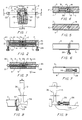
- FIG. 1 is a fragmentary plan view of a ski equipped with the preferred embodiment of the invention wherein the probe assembly is incorporated in the ski by the ski manufacturer at the time the ski is fabricated. Portions of the ski structure are broken away to reveal underlying parts, some of which parts are shown in elevation and some in cross-section for clarity.
- FIG. 2 is a vertical cross-sectional view taken in the plane indicated by the line 2-2 in FIG. 1, showing the probe assembly in active position.
- FIG. 3 is a vertical cross-sectional view similar to FIG. 2, but showing the probe assembly pivoted to inactive position.
- FIG. 4 is a fragmentary horizontal cross-sectional view taken in the plane indicated by the line 4-4 in FIG. 1.
- FIG. 5 is a fragmentary vertical cross-sectional view taken in the plane indicated by the line 5-5 in FIG. 3.
- FIG. 6 is a fragmentary elevational view showing the probe assembly deployed in active position.
- FIG. 7 is a fragmentary elevational view showing the probe assemly in retracted inactive position.
- FIG. 8 is an elevational view illustrating a tool in operative association with the probe assembly to effect pivotal displacement of the probe assembly from operative position to inoperative position or vise versa.
- FIG. 9 is an elevational view illustrating use of the tool to effect a depth adjustment of the probe.
- FIG. 10 is a fragmentary plan view similar to FIG. 1 illustating the integral probe assembly of FIG. 1 equippped with a probe actuating assembly mounted on the ski and manipulable by the skier by hand or by use of a ski pole. A portion of the structure is broken away to reveal underlying parts.
- FIG. 11 is a vertical cross-sectional view taken in the plane indicated by the line 11-11 in FIG. 10.
- FIG. 12 is a fragmentary vertical cross-sectional view taken in the plane indicated by the line 12-12 in FIG. 10.
- FIG. 13 is a fragmentary vertical cross-sectional view taken in the plane indicated by the line 13-13 in FIG. 11.
- FIG. 14 is a fragmentary elevational view of one side edge illustrating the various positions to which the probes may be adjusted.
- FIG. 15 is a fragmentary side elevational view of a second embodiment of the invention adapted for "integral" incorporation or retro-fit on a ski after manufacture of the ski.
- FIG. 16 is a fragmentary plan view of the embodiment of the invention illustrated in FIG. 15.
- the method and means described and illustrated herein enhances the safe enjoyment of downhill skiing by significantly reducing the level of skill and physical strength required to participate in the sport.
- this invention will augment the numbers of individuals particupating in the sport, and will serve to diminish the number of injuries sustained by such participants resulting from such participants being inadvertently caught in a dangerous situation beyond the threshold of their ability.
- the method and means described and illustrated herein places at the disposal of the skier means for enhanced control over both drag and maneuverability.
- FIGS. 1 through 7 inclusive there is there shown in top plan view a fragmentary portion of a snow ski 2 having a top surface 3, a bottom surface 4 and left and right side edges 6 and 7, respectively.
- the surface 3 of the ski constitutes the skier support surface, while the under surface 4 of the ski constitutes the "running" surface of the ski that is in contact with the snow while the ski is in use.
- an adjustable probe assembly designated generally by the numeral 8 and including a support member 9 embedded in the body 12 of filler material that lies laminated between the top surface 3 and the bottom surface 4, both of which surfaces are conventionally fabricated from an appropriate aluminum alloy.
- the body of filler material 12 may conveniently be formed from balsa wood or from an appropriate rigid synthetic foam material while the lateral side edges 6 and 7 are formed by an appropriate synthetic material sealed to the mutually facing edge surface portions of the aluminum alloy top and bottom surface members 3 and 4, thus sealing the interior of the ski structure to prevent the migration of moisture thereinto.
- the support member 9 being embedded in the body of filler material 12, lies immovable therein, and serves as an adequate support base for a generally cylindrical cam block 13 rotatable about a transverse axis that extends generally perpendicular to the longitudinal dimension of the ski.
- the cam block 13 is provided with a generally cylindrical outer periphery that is in turn provided with a pair of circumferentially spaced recesses 14 and 16 shown in FIGS. 1 and 4.
- the cylindrical cam block 13 is mounted in association with the inner mutually overlapping semi-cylindrical end portions 17 and 18 of laterally projecting axle members 19 and 21, respectively, that extend transversely through the interior body of filler material and project laterally beyond the side edges 6 and 7 of the ski in exterior portions 22 and 23.
- the exterior end portions 22 and 23 of the rotatable and axially aligned transversely extending axles 19 and 21 serve to mount, respectively, tubular probe holders 24 and 26, the interior peripheries of which are appropriately threaded to threadably receive adjustable probe members 27 and 28.
- the probe holders 24 and 26, with adjustable probes 27 and 28 threadably secured therein may be rotated from an active position as illustrated in FIG. 2, wherein the probes 27 and 28 extend a predetermined and adjustable distance below the running surface 4 of the ski, so as to project into the snow and thereby provide a measurable amount of drag on the ski.
- the probe holders 24 and 26 with attendant probes 27 and 28 may be pivoted into an inactive position as illustrated in FIG. 7, by pivotal rotation of the axle members 19 and 21 so that the longitudinal axis of the probe holders 24 and 26 and the attendant probes 27 and 28 lie substantially parallel to the longitudinal axis of the ski 2 as illustrated in FIG. 7.
- the probe assembly To retain the probe assembly in its adjusted position, the probe assembly includes a spring-pressed detent arrangement including a spherical ball 29 (FIGS. 1 and 2) resiliently pressed against the outer periphery of the cam block 13 by a coil compression spring 31 as shown.
- the coil compression spring 31 lies in a bore 32 formed axially in the support member 9 as shown, and cooperates with the spherical ball 29 and the recesses 14 and 16 formed in the periphery of the cam block 13 to retain the cam block in one or the other of the positions to which it is shifted by rotation of the probe holders 24 and 26 as previously discussed.
- the overlapped semi-cylindrical portions 17 and 18 are fixedly joined by an appropriate pin 33 as shown in FIGS. 1 and 2.
- the cam block 13 cooperating with the detent ball 29 and compression spring 31 controls the rotational orientation of the probe holders 24 and 26 and through them the probes 27 and 28.
- These elements provide probe drag load control to maintain a smooth ride under varying snow conditions.
- the cam begins to rotate, which reduces probe drag to maintain equilibrium.
- the mechanism returns to the fully engaged position illustrated in FIG. 2.
- the cam also provides a stable disengaged position.
- This position can be reached either by manual disengagement of the probe and probe holders as will hereinafter be explained, or by safety disengagement due to a sufficiently high force such as contact with a solid object lying in the snow and struck by one of the probes whereby a rotational moment will be applied to the probe assembly to cause full retraction of the probe assembly.
- a manual engagement and depth control adjustment tool is provided designated generally by the numeral 36 and illustrated in FIGS. 8 and 9.
- the tool 36 facilitates field adjustments of the probe assembly, and comprises a handle 10, and a probe holder engagement member 37 constituting a semi-cylindrical socket adapted to slip snugly over the generally cylindrical exterior periphery of the probe holders 24 and 26 as shown in FIG. 8. All that is required to readjust the position of the probe holders and probes is to turn the tool through approximately a 90 degree angle to shift the spherical ball 29 from one detent recess 14 to the other detent recess 16.
- the tool 36 When used to adjust the depth of penetration of the probes 27 and 28 in the snow, the tool 36 is provided with a generally cylindrical socket member 38 recessed as shown in FIG. 9 to receive the head of a probe whereby appropriate rotational movement of the tool about the axis of the probe holder and probe will cause the probe to be adjusted in relation to the probe holder so as to project more or less below the lower running surface 4 of the ski. Since in most instances, both of the probes 27 and 28 will be adjusted so that both probes project equally from their respective probe holders, it will be noted that the handle 10 of the tool is provided with a section having a width A that corresponds generally to the maximum desirable extension of the probe, while the more narrow neck portion of the handle designated by the dimension B, correlates to the minimum depth adjustment of the probe.
- the probes may be adjusted beyond these minimum and maximum ranges, and may be done so accurately for comparison purposes between the two probes by counting the number of rotations applied to each probe. Since the pitch of the threads which provide adjustable engagement between the probes and the probe holders is the same on both probes, obviously, a 360 degree rotation of the probes will advance or retract them by equal increments.
- FIGS. 10 through 14 fulfills that need.
- a probe assembly actuating apparatus designated generally by the numeral 41 and including an elongated rack member 42 slidably disposed within an appropriate slot formed in the body of filler material 12 and having a plurality of teeth 43 adapted to engage complementary teeth 44 formed on the periphery of one of the axles 19 or 21, here shown to be formed on the axle 19.
- a rotatable thumb nut 52 appropriately threaded to engage a nut 53 disposed within the ski below the top surface thereof, and adapted to move up and down as indicated by the arrow depending upon the direction and degree of rotation of the thumb nut 52.
- a projecting tongue 54 on the nut 53 engages a tongue 56 on the toggle 46 to limit the degree of pivotal rotation of the toggle 46 to thus permit setting of the probe angles to something less than 90 degrees to the running surface 4 of the ski. This alternate position is illustrated in FIG.
- the probe 26 may be set at full depth penetration when it is set at a 90 degree angle to the running surface 4 of the ski or, alternatively, may be set at approximately 45 degrees as illustrated in broken lines, or may be retracted completely, also as shown by the broken lines.
- the detent structure works identically as previously described.
- FIGS. 1 through 14 relate to a probe assembly that is assembled and incorporated into a ski by the ski manufacturer, it is clear that there are instances in which owners of skis not so equipped with the probe assembly would want to equip their skis with such an assembly, and it is for this purpose that I have provided the embodiment of the invention as illustrated in FIGS. 15 and 16.
- a ski 61 having a longitudinal axis 62, a top surface 63 and a bottom surface 64.
- the ski is manufactured as described above, to have top and bottom surfaces formed from an appropriate aluminum alloy with a body of filler material disposed and laminated between the top and bottom surface members, the side edges 66 of the ski constituting a layer of tough synthetic resinous material disposed between the top and bottom surface layers as previously discussed.
- each ski Mounted on each ski are a pair of side plates 67 which are mirror images of each other, and only one of which is illustrated in FIGS. 15 and 16 in the interest of brevity in this description.
- the side plates 67 are conveniently fabricated from an appropriate metal, such as an aluminum alloy, but may be fabricated from other suitable material such as stainless steel.
- the two side plates 67 are bound to the opposing side edges 66 by means of a threaded rod 68 that extends transversely through the ski medianly between the top and bottom surfaces 63 and 64, and in a manner to intersect the longitudinal center line 62 of the ski.
- Each of the side plates 67 is appropriately bored as shown, and the bore threaded to be engaged by the threaded end portion of the rod 68 that projects through the side edge 66 as illustrated.
- a second rod 69 also extends transversely through the ski from one side to the other, and passes through a journal bore 71 formed in the mounting plate 67 to provide a smooth outer end portion 72 on opposite sides of the ski on which are mounted a pair of mounting blocks 73 formed with a lip 74 and a slot 76 extending vertically in one side of the block, and adapted to accommodate an elongated pin 77 lying in the slot 76 and passing through the end portion 72 of the shaft 69 to retain the mounting block on the shaft.
- the block 73 is also provided with a bifurcated extension 78 for purposes which will hereinafter be explained.
- the mounting plate 67 is provided with a bearing pad 79 of some appropriate synthetic resinous material that provides the low friction characteristic desired in the bearing pads 79.
- a probe 81 mounted on each of the mounting blocks 73 is a probe 81, conveniently from 0.3 cm (1/8") diameter to approximately 0.6 cm (1/4") in diameter, and appropriately threaded as illustrated to threadably engage a complementarily threaded bore 82 formed in the mounting block 73 as shown.
- the threaded interconnection between each probe 81 and the mounting block 73 with which it is associated enables each probe to be adjusted in terms of the extent of projection from the block on which it is mounted, and to thereby adjust the depth of penetration of the probe in the snow over which the ski moves.
- a spring pressed toggle arrangement designated generally by the numeral 83 and including a pivot bearing 84 rotatably mounted on the mounting plate 67 and through which passes a threaded spindle 86 having an abutment 87 at its end adjacent the bifurcated portion 78 of the mounting block 73, and an apertured lug 88 pivotally connected to the bifurcated projection 78 by an appropriate pin 89.
- a coil compression spring 91 mounted on the spindle 86 between the pivot block 84 and the abutment block 87 is a coil compression spring 91.
- an adjustment nut 92 Mounted on the end of the threaded spindle 86 is an adjustment nut 92 which upon rotation may shorten or lengthen the effective length of the threaded spindle 86 to effectively adjust the angular position of the probe 81 in relation to the lower running surface 64 of the ski.
- the probe 81 moves to the right as viewed in FIG. 1, thus diminishing the angle of the probe in relation to the lower surface 64 to something less than 90 degree. If it is desired to completely retract the probe 81 from projecting below the lower running surface 64 of the ski, all that is required is that a downward pressure be applied on the abutment 87 as indicated by the arrow so as to shift the position of the toggle to reposition the bifurcated portion 78 to the disengaged alternate position as illustrated in broken lines in FIG. 15. When this occurs, the probes 81 will be shifted to their position in which they lie substantially adjacent the side surfaces 66 of the ski as shown in broken lines in FIG. 15.
- the tension in the spring 91 may be adjusted by adjustment of the nut 92 to thus vary the force that is required to be imposed against the deployed probes 81 that will cause them to be resiliently disengaged during a downhill run.
- the tension in the spring 91 may be adjusted by adjustment of the nut 92 to thus vary the force that is required to be imposed against the deployed probes 81 that will cause them to be resiliently disengaged during a downhill run.
Landscapes
- Footwear And Its Accessory, Manufacturing Method And Apparatuses (AREA)
- Investigating Or Analyzing Materials By The Use Of Magnetic Means (AREA)
- Length Measuring Devices With Unspecified Measuring Means (AREA)
- Control Of Position, Course, Altitude, Or Attitude Of Moving Bodies (AREA)
Claims (7)
- In Kombination, Schneeski (2) mit einem langgestreckten Körper, der durch eine obere Skihaltefläche (3) und eine durch laterale Seitenrandflächen (6-7) begrenzte untere Schnee-Eingriffs-Fahrfläche (4) begrenzt ist, und mit einem Skistiefelanbringungsmittel, das ein an der oberen Skihaltefläche (3) befestigtes zehenseitiges Stück aufweist, und eine integrale Fingeranordnung (8), die an dem Ski angebracht ist und ein Paar von Steuerflächen (27-28) aufweist, die nahe den gegenüberliegenden Seitenrandflächen (6-7) angeordnet sind und zum Eingriff mit dem Schnee selektiv ausstreckbar sind, damit durch Ausübung herkömmlicher Körperbewegungen zum Ausüben von Hilfssteuerkräften auf den Ski, wenn sich dieser bezüglich des Schnees bewegt, hierdurch die Ski eine verbesserte Steuerung über den Fahrwiderstand und eine verbesserte Manövrierbarkeit erlangen können, welche integrale Fingeranordnung umfaßt:a) eine Achsenstange (19, 21), die quer durch den Ski (2) zwischen den oberen (3) und unteren (4) Flächen verläuft und Endabschnitte (22 -23) aufweist, die nahe den lateralen Seitenrandflächen (6-7) enden;b) Fingerteile (27-28), die an den gegenüberliegenden Endabschnitten der Achsenstange (19, 21) nahe den lateralen Seitenrändern (6, 7) in der Nähe des zehenseitigen Teils angebracht sind und selektiv drehbar einstellbar sind zwischen einer rückgezogenen Position, in der die Fingerteile (27-28) bei Verwendung des Skis (2) außer Kontakt mit dem Schnee stehen, und einer ausgestreckten Position, in der die Fingerteile (27-28) unter die untere Fahrfläche (4) des Skis vorstehen und in den Schnee, in dem der Ski (2) fährt, eindringen; undc) Mittel (13, 29, 31), die der Achsenstange (19, 21) zugeordnet sind und einen Teil der integralen Fingeranordnung bilden, um die Fingerteile (27-28) in einer ausgewählten ausgestreckten Position zu halten;d) wobei die Fingerteile (27-28) quer zu der Achsenstange (19-21) verlaufen, wodurch eine selektive Dreheinstellung der Fingerteile (27-28) um die Achse der Achsenstange (19-21) den Schwenkwinkel der Fingerteile (27-28) bezüglich der unteren Fahrfläche (4) des Skis (2) verändert, um hierdurch die Eindringtiefe in den Schnee durch die Finger (27-28) zu steuern.
- Kombination nach Anspruch 1, in der die Fingerteile (27-28) jeweils eine bogenförmige Fläche umfassen, die zum Aufstossen auf den Schnee geeignet ist, wenn die Fingerteile (27-28) ausgestreckt sind und der Ski (2) über den Schnee fährt.
- Kombination nach Anspruch 1, in der die Achsenstange (19, 21) zwei mit ihren Enden verbundene langgestreckte Stangen (19, 21) umfaßt, wobei ein Lagerblock (13) in dem Ski (2) zwischen den oberen (3) und unteren (4) Flächen angebracht ist und die miteinander verbundenen Enden (17-18) der zwei langgestreckten Stangen (19, 21) festhaltend umgibt, wodurch der Lagerblock (13) und die Achsenstange (19, 21) gemeinsam um die Längsachse der Achsenstange drehbar sind.
- Kombination nach Anspruch 1, in der das Mittel (13, 29, 31), das der Achsenstange (19, 21) zum Halten der Fingerteile (27, 28) in einer ausgewählten Position zugeordnet ist, aufweist: einen Lagerblock (13) der in dem Ski (2) zwischen den oberen (3) und unteren (4) Flächen drehbar angebracht ist und mit der Achsenstange (19, 21) axial fluchtet und an dieser befestigt ist und eine darin ausgebildete Rastausnehmung (14, 16) aufweist, eine Rastkugel (29), die zum selektiven Eingriff mit der Rastausnehmung oder zur Trennung von dieser geeignet ist, und eine Feder (31), welche die Rastkugel (29) in eine Richtung zum Eingriff mit der Rastausnehmung (14, 16) federnd vorspannt.
- Kombination nach Anspruch 1, in der die Achsenstange (19, 21) an jedem gegenüberliegenden Ende mit einem Fingerteilhalter (24-26) versehen ist und ein Fingerteil (27-28) in jedem der Halter (24, 26) einstellbar angebracht ist, wodurch der Vorstehgrad des Fingerteils (27) über die untere Fläche (4) des Skis (2) hinaus einstellbar ist, um den Widerstandskoeffizienten der Finger (27-28) in dem Schnee zu ändern.
- Kombination nach Anspruch 5, in dem ein Paar von Halteplatten (67) an gegenüberliegenden Seitenrändern (66) des Ski (61) befestigt ist, wobei die Achsenstange (69) an dem Paar von Halteplatten (67) angelenkte Endabschnitte (72) umfaßt, die Fingerteilhalter (73) an den Achsenstangenendabschnitten (72) zur Schwenkbewegung um die Längsachse der Achsenstange (69) herum angebracht sind, und das Mittel (86, 91, 88) zum Halten der Fingerteile (81) in einer gewählten Stellung eine an jeder Halteplatte (67) angebrachte federbelastete Kippanordnung (83) umfaßt, wodurch die Betätigung der Kippanordnung (83) in eine Richtung ein Ausstrecken der Fingeranordnung (81) zum Vorstehen in den Schnee bewirkt und eine Betätigung der Kippanordnung (83) in die entgegengesetzte Richtung ein Rückziehen der Fingerteile (81) bewirkt, so daß diese bei Verwendung des Ski nicht mit dem Schnee in Eingriff treten.
- Kombination nach Anspruch 6, in der Mittel (86, 87, 92, 78) an der Kippanordnung (83) vorgesehen sind, um den Schwenkgrad der Fingerteile (81) bezüglich der unteren Fahrfläche (64) des Ski einzustellen.
Applications Claiming Priority (3)
| Application Number | Priority Date | Filing Date | Title |
|---|---|---|---|
| US07/318,738 US4911461A (en) | 1989-03-03 | 1989-03-03 | Downhill skis incorporating integral probe assembly for controlling speed and maneuverability |
| PCT/US1990/001180 WO1990009819A1 (en) | 1989-03-03 | 1990-03-02 | Downhill skis incorporating integral probe assembly |
| US318738 | 2002-12-13 |
Publications (3)
| Publication Number | Publication Date |
|---|---|
| EP0471675A1 EP0471675A1 (de) | 1992-02-26 |
| EP0471675A4 EP0471675A4 (en) | 1992-08-05 |
| EP0471675B1 true EP0471675B1 (de) | 1995-02-01 |
Family
ID=23239410
Family Applications (1)
| Application Number | Title | Priority Date | Filing Date |
|---|---|---|---|
| EP90904529A Expired - Lifetime EP0471675B1 (de) | 1989-03-03 | 1990-03-02 | Abfahrtsski mit integrierter sondeneinheit |
Country Status (5)
| Country | Link |
|---|---|
| US (1) | US4911461A (de) |
| EP (1) | EP0471675B1 (de) |
| AT (1) | ATE117903T1 (de) |
| DE (1) | DE69016653T2 (de) |
| WO (1) | WO1990009819A1 (de) |
Families Citing this family (11)
| Publication number | Priority date | Publication date | Assignee | Title |
|---|---|---|---|---|
| US4986561A (en) * | 1987-11-27 | 1991-01-22 | Humphrey Engineering, Inc. | Method and apparatus for speed and maneuverability control for downhill skiing |
| US5370415A (en) * | 1993-01-07 | 1994-12-06 | Humphrey; John M. | Ski control system with carve control amplification |
| DE9401077U1 (de) * | 1994-01-22 | 1994-04-07 | Lang, Fritz, 87766 Memmingerberg | Bremsvorrichtung für einen Langlauf-Ski |
| US6562906B2 (en) * | 2000-08-11 | 2003-05-13 | E. I. Du Pont De Nemours And Company | Bi-modal ionomers |
| US6866273B2 (en) | 2000-12-08 | 2005-03-15 | The Burton Corporation | Sliding device |
| US20050121480A1 (en) * | 2003-09-15 | 2005-06-09 | Erik Cooley | Systems and methods for providing a self-arresting device |
| US20120297646A1 (en) * | 2011-05-23 | 2012-11-29 | Jean Brault | Multi-adaptable power automated traction apparatus |
| US9326567B2 (en) * | 2011-05-23 | 2016-05-03 | Jean Brault | Multi-adaptable power automated traction apparatus |
| US8905199B2 (en) | 2012-06-20 | 2014-12-09 | Samuel J. Mann | Control system for downhill skis |
| US9643075B2 (en) * | 2014-07-07 | 2017-05-09 | Jean Brault | Power-automated traction for skis |
| US10926148B2 (en) * | 2017-03-08 | 2021-02-23 | David Chalfant Manley | Snowboard training support apparatus |
Family Cites Families (20)
| Publication number | Priority date | Publication date | Assignee | Title |
|---|---|---|---|---|
| AT14420B (de) * | 1903-01-27 | 1903-12-10 | Franz Wassermann | Schneeschuh-Bergsteigevorrichtung. |
| FR736916A (fr) * | 1932-05-10 | 1932-12-05 | Dispositif de contre-recul et de freinage pour skis | |
| DE650475C (de) * | 1935-12-12 | 1937-09-23 | Erwin Ort | In einem lotrechten Laengsschlitz am Ski versenkt angebrachtes Steig- und Harscheisen |
| FR816949A (fr) * | 1937-01-28 | 1937-08-20 | Perfectionnements aux skis | |
| CH354704A (de) * | 1957-02-14 | 1961-05-31 | Gertsch Ernst | Sicherheits-Skibindung |
| US3195911A (en) * | 1963-01-10 | 1965-07-20 | Mitchell H Cubberley | Loose ski arresting device |
| US3295859A (en) * | 1964-06-04 | 1967-01-03 | Elijah R Perry | Metal ski having a pair of grooves at the opposite edges thereof |
| FR2208691A2 (de) * | 1972-11-27 | 1974-06-28 | Lacarrau Philippe | |
| FR2213784B1 (de) * | 1973-01-16 | 1976-08-27 | Salomon & Fils F | |
| US4227714A (en) * | 1974-03-05 | 1980-10-14 | Etablissements Francois Salomon Et Fils | Automatic ski brake using stirrup-shaped spring wire |
| US3918730A (en) * | 1974-11-29 | 1975-11-11 | Olin Corp | Ski stopper |
| US3980322A (en) * | 1974-11-29 | 1976-09-14 | Olin Corporation | Ski stopper |
| DE2548667A1 (de) * | 1975-10-30 | 1977-06-16 | Trak Sportartikel Gmbh | Skibremse |
| AT350947B (de) * | 1975-11-25 | 1979-06-25 | Tyrolia Freizeitgeraete | Fangeinrichtung fuer skier |
| DE2600850A1 (de) * | 1976-01-12 | 1977-07-14 | Karl Altenburger | Bremsvorrichtung fuer skier |
| US4152007A (en) * | 1977-04-22 | 1979-05-01 | Smith Jack E | Ski brake |
| US4219214A (en) * | 1977-12-19 | 1980-08-26 | Kostov Dimitar C | Ski brake |
| US4227708A (en) * | 1978-11-29 | 1980-10-14 | Bernard Cote | Ski brake |
| US4312517A (en) * | 1980-02-14 | 1982-01-26 | Spademan Richard George | Releasable ski binding with ski brake locating stop |
| DE3543829A1 (de) * | 1985-12-12 | 1987-06-19 | Reuters Karl Josef | Einrichtung zur anordnung an einem ski |
-
1989
- 1989-03-03 US US07/318,738 patent/US4911461A/en not_active Expired - Lifetime
-
1990
- 1990-03-02 WO PCT/US1990/001180 patent/WO1990009819A1/en not_active Ceased
- 1990-03-02 EP EP90904529A patent/EP0471675B1/de not_active Expired - Lifetime
- 1990-03-02 AT AT90904529T patent/ATE117903T1/de not_active IP Right Cessation
- 1990-03-02 DE DE69016653T patent/DE69016653T2/de not_active Expired - Fee Related
Also Published As
| Publication number | Publication date |
|---|---|
| DE69016653D1 (de) | 1995-03-16 |
| DE69016653T2 (de) | 1995-08-31 |
| US4911461A (en) | 1990-03-27 |
| EP0471675A1 (de) | 1992-02-26 |
| ATE117903T1 (de) | 1995-02-15 |
| EP0471675A4 (en) | 1992-08-05 |
| WO1990009819A1 (en) | 1990-09-07 |
Similar Documents
| Publication | Publication Date | Title |
|---|---|---|
| US5833252A (en) | Lateral sliding roller board | |
| EP0500991B1 (de) | Skate board für Strassenfahren | |
| US3827706A (en) | Wheeled skis | |
| US4007946A (en) | Short ski | |
| US6070885A (en) | Off-line roller skates | |
| US5401037A (en) | Composite wheels for in-line roller skates | |
| US5299815A (en) | Roller skate braking device | |
| EP0471675B1 (de) | Abfahrtsski mit integrierter sondeneinheit | |
| EP0496352A1 (de) | Monoski | |
| US4995631A (en) | Mono-ski deep side cuts for user stability control | |
| US20120126523A1 (en) | Laterally sliding roller ski | |
| CN101745213B (zh) | 滑板 | |
| US4094524A (en) | Skate board braking and steering system | |
| US3645347A (en) | Guide means for skis | |
| DE2621473A1 (de) | Zweiraedriger rollschuh | |
| US5860492A (en) | Hand-activated brake and method | |
| JP2004534626A (ja) | カービング小型そり | |
| US5791665A (en) | Roller skate with brake | |
| US4986561A (en) | Method and apparatus for speed and maneuverability control for downhill skiing | |
| US4349209A (en) | Snow shuttle | |
| US20050029757A1 (en) | Swivelable mount for attaching a binding to a snowboard | |
| US5145200A (en) | Universal integral ski control system | |
| EP0318041B1 (de) | Vorrichtung zur Kontrolle der Abfahrtskigeschwindigkeit und der Abfahrtskimanövrierbarkeit | |
| CA1324180C (en) | Ice and snow surf-board | |
| JPH05329243A (ja) | 走行運動具 |
Legal Events
| Date | Code | Title | Description |
|---|---|---|---|
| PUAI | Public reference made under article 153(3) epc to a published international application that has entered the european phase |
Free format text: ORIGINAL CODE: 0009012 |
|
| 17P | Request for examination filed |
Effective date: 19911127 |
|
| AK | Designated contracting states |
Kind code of ref document: A1 Designated state(s): AT CH DE FR GB IT LI SE |
|
| A4 | Supplementary search report drawn up and despatched |
Effective date: 19920612 |
|
| AK | Designated contracting states |
Kind code of ref document: A4 Designated state(s): AT CH DE FR GB IT LI SE |
|
| 17Q | First examination report despatched |
Effective date: 19931112 |
|
| GRAA | (expected) grant |
Free format text: ORIGINAL CODE: 0009210 |
|
| AK | Designated contracting states |
Kind code of ref document: B1 Designated state(s): AT CH DE FR GB IT LI SE |
|
| PG25 | Lapsed in a contracting state [announced via postgrant information from national office to epo] |
Ref country code: IT Free format text: LAPSE BECAUSE OF FAILURE TO SUBMIT A TRANSLATION OF THE DESCRIPTION OR TO PAY THE FEE WITHIN THE PRESCRIBED TIME-LIMIT;WARNING: LAPSES OF ITALIAN PATENTS WITH EFFECTIVE DATE BEFORE 2007 MAY HAVE OCCURRED AT ANY TIME BEFORE 2007. THE CORRECT EFFECTIVE DATE MAY BE DIFFERENT FROM THE ONE RECORDED. Effective date: 19950201 Ref country code: CH Effective date: 19950201 Ref country code: FR Effective date: 19950201 Ref country code: AT Effective date: 19950201 Ref country code: LI Effective date: 19950201 |
|
| REF | Corresponds to: |
Ref document number: 117903 Country of ref document: AT Date of ref document: 19950215 Kind code of ref document: T |
|
| REF | Corresponds to: |
Ref document number: 69016653 Country of ref document: DE Date of ref document: 19950316 |
|
| PG25 | Lapsed in a contracting state [announced via postgrant information from national office to epo] |
Ref country code: SE Effective date: 19950501 Ref country code: GB Effective date: 19950501 |
|
| REG | Reference to a national code |
Ref country code: CH Ref legal event code: PL |
|
| EN | Fr: translation not filed | ||
| GBPC | Gb: european patent ceased through non-payment of renewal fee |
Effective date: 19950501 |
|
| PLBE | No opposition filed within time limit |
Free format text: ORIGINAL CODE: 0009261 |
|
| STAA | Information on the status of an ep patent application or granted ep patent |
Free format text: STATUS: NO OPPOSITION FILED WITHIN TIME LIMIT |
|
| 26N | No opposition filed | ||
| PGFP | Annual fee paid to national office [announced via postgrant information from national office to epo] |
Ref country code: DE Payment date: 20000331 Year of fee payment: 11 |
|
| PG25 | Lapsed in a contracting state [announced via postgrant information from national office to epo] |
Ref country code: DE Free format text: LAPSE BECAUSE OF NON-PAYMENT OF DUE FEES Effective date: 20020101 |