EP0318041B1 - Vorrichtung zur Kontrolle der Abfahrtskigeschwindigkeit und der Abfahrtskimanövrierbarkeit - Google Patents
Vorrichtung zur Kontrolle der Abfahrtskigeschwindigkeit und der Abfahrtskimanövrierbarkeit Download PDFInfo
- Publication number
- EP0318041B1 EP0318041B1 EP88119704A EP88119704A EP0318041B1 EP 0318041 B1 EP0318041 B1 EP 0318041B1 EP 88119704 A EP88119704 A EP 88119704A EP 88119704 A EP88119704 A EP 88119704A EP 0318041 B1 EP0318041 B1 EP 0318041B1
- Authority
- EP
- European Patent Office
- Prior art keywords
- ski
- probe
- skier
- drag
- probes
- Prior art date
- Legal status (The legal status is an assumption and is not a legal conclusion. Google has not performed a legal analysis and makes no representation as to the accuracy of the status listed.)
- Expired - Lifetime
Links
- 239000000523 sample Substances 0.000 claims abstract description 194
- 230000033001 locomotion Effects 0.000 claims abstract description 19
- 230000035515 penetration Effects 0.000 abstract description 15
- 238000000034 method Methods 0.000 abstract description 10
- 230000005484 gravity Effects 0.000 description 26
- 230000007246 mechanism Effects 0.000 description 22
- 230000008901 benefit Effects 0.000 description 13
- 238000013461 design Methods 0.000 description 9
- 230000000694 effects Effects 0.000 description 8
- 230000006870 function Effects 0.000 description 8
- 210000003205 muscle Anatomy 0.000 description 7
- 206010050031 Muscle strain Diseases 0.000 description 5
- 230000006378 damage Effects 0.000 description 5
- 210000003127 knee Anatomy 0.000 description 5
- 208000027418 Wounds and injury Diseases 0.000 description 4
- 230000001133 acceleration Effects 0.000 description 4
- 230000006835 compression Effects 0.000 description 4
- 238000007906 compression Methods 0.000 description 4
- 208000014674 injury Diseases 0.000 description 4
- 230000009471 action Effects 0.000 description 3
- 230000027455 binding Effects 0.000 description 3
- 238000009739 binding Methods 0.000 description 3
- 230000008859 change Effects 0.000 description 3
- 239000012530 fluid Substances 0.000 description 3
- 238000005381 potential energy Methods 0.000 description 3
- 238000013519 translation Methods 0.000 description 3
- 239000002131 composite material Substances 0.000 description 2
- 230000007423 decrease Effects 0.000 description 2
- 238000006073 displacement reaction Methods 0.000 description 2
- 239000002184 metal Substances 0.000 description 2
- 230000007935 neutral effect Effects 0.000 description 2
- 230000010355 oscillation Effects 0.000 description 2
- 238000004806 packaging method and process Methods 0.000 description 2
- 230000002093 peripheral effect Effects 0.000 description 2
- 230000001681 protective effect Effects 0.000 description 2
- 230000009467 reduction Effects 0.000 description 2
- 230000002459 sustained effect Effects 0.000 description 2
- 238000012360 testing method Methods 0.000 description 2
- 206010049565 Muscle fatigue Diseases 0.000 description 1
- 239000000654 additive Substances 0.000 description 1
- 230000000996 additive effect Effects 0.000 description 1
- 238000013459 approach Methods 0.000 description 1
- 230000000712 assembly Effects 0.000 description 1
- 238000000429 assembly Methods 0.000 description 1
- 230000009286 beneficial effect Effects 0.000 description 1
- 230000000295 complement effect Effects 0.000 description 1
- 239000012141 concentrate Substances 0.000 description 1
- 238000013016 damping Methods 0.000 description 1
- 230000002939 deleterious effect Effects 0.000 description 1
- 230000000881 depressing effect Effects 0.000 description 1
- 230000003467 diminishing effect Effects 0.000 description 1
- 238000002347 injection Methods 0.000 description 1
- 239000007924 injection Substances 0.000 description 1
- 238000003780 insertion Methods 0.000 description 1
- 230000037431 insertion Effects 0.000 description 1
- 210000002414 leg Anatomy 0.000 description 1
- 230000014759 maintenance of location Effects 0.000 description 1
- 239000000463 material Substances 0.000 description 1
- 239000002991 molded plastic Substances 0.000 description 1
- 239000004033 plastic Substances 0.000 description 1
- 239000000843 powder Substances 0.000 description 1
- 230000008569 process Effects 0.000 description 1
- 230000002829 reductive effect Effects 0.000 description 1
- 230000002787 reinforcement Effects 0.000 description 1
- 230000000717 retained effect Effects 0.000 description 1
- 230000000979 retarding effect Effects 0.000 description 1
- 230000002441 reversible effect Effects 0.000 description 1
- 238000012552 review Methods 0.000 description 1
- 239000011435 rock Substances 0.000 description 1
- XLYOFNOQVPJJNP-UHFFFAOYSA-N water Substances O XLYOFNOQVPJJNP-UHFFFAOYSA-N 0.000 description 1
Images


Classifications
-
- A—HUMAN NECESSITIES
- A63—SPORTS; GAMES; AMUSEMENTS
- A63C—SKATES; SKIS; ROLLER SKATES; DESIGN OR LAYOUT OF COURTS, RINKS OR THE LIKE
- A63C11/00—Accessories for skiing or snowboarding
Definitions
- the present invention relates to a ski having a ski boot attachment toe piece fixed on an upper skier support surface and a control assembly mounted on said upper skier support surface.
- a ski known from DE 32 23 413 A1 of this type comprises protective edges which at least over part of their length relative to the plane of the running surface can be adjusted vertically with respect thereto or are pivotable about axes extending in the longitudinal direction of the ski, and can be justed in different positions by adjusting means to thereby increase the influence of the protective edges onto the ski in case of changes of direction and running of the ski on icy surfaces.
- US-A-3,980,322, 3,195,911, 4,103,916, 3,873,108, 3,918,730, 3,048,418, 4,062,561, 4,312,517, 3,909,024 and 4,227,714 relate to situations where a ski has been separated from a skier and is loose on a ski slope and apt to cause some damage or injury to skiers unless stopped. These "loose ski brake" devices do not operate during active skiing.
- US-A-4,152,007 provides snow plows at the rear ends of skis that are activated by hydraulic pressure controlled through grips on ski poles. There must be come connection between the grips on the ski poles and the snow plows and this in itself is a disadvantage in that the skier is prevented from utilizing the ski poles as freely as he might for the purpose for which they are intended.
- the snow plows provide active drag control. The characteristics of these snow plows are in sharp contrast with an enhanced maneuverability. Because the plows are at the rear ends of the skis and therefore far behind the skier's center of gravity, they actually tend to prevent the skier from turning while they are engaged.
- US-A-4,227,708 relates to a ski brake that comprises a plate fixed on the upper surface of the ski.
- the plate is provided with a notch into which the lower end of a ski pole may be inserted to produce drag against the snow.
- this device does not provide enhanced maneuverability or control by natural body motions. Maneuverability is an essential difference between downhill skiing and cross-country skiing. The bindings of cross-country skis naturally limit maneuverability. Since this device applies drag only on the outside of the skis, downhill braking would tend to spread the tips of the skis, making the skis even more difficult to maneuver. Use of the ski poles as braking levers violates the natural motions of downhill skiing which requires upper body movement and free use of the poles.
- skier For those that are experienced skiers, it will be obvious that skiing on a steep slope requires considerably more physical effort and skill than skiing on a gentle slope. Turning maneuvers to reduce speed require the skier to generate a force in opposition to the force tending to propel the skier downhill. This force, multiplied by the skier's velocity, equates with the power the skier must exert to maintain speed control on the slope. Steeper slopes require both a greater maximum force and a greater average power which together require greater strenght and endurance from the skier. Expert skiers have several advantages over less advanced skiers. First, since they have a higher ability threshold, a greater fraction of the potential energy during the run is consumed in aerodynamic and ski drag. Second, since they are more skillful, they are able to make turns with less muscle strain. Although expert skiers still must exert the same force as less experienced skiers, they apply it more effectively in reducing speed.
- the primary object of the present invention is to enhance the safe enjoyment of downhill skiing by significantly reducing the level of skill and physical strength required to participate in the sport.
- the ski of the above-described type is characterized by at least one pin-shaped control probe comprising a control surface mounted generally adjacent to said toe piece in combination with means for selectively deploying said control probe to penetrate the snow to enable downhill skier, through the execution of conventional body movements, to impart auxiliary control forces on said ski as it moves in relation to the snow to provide enhanced control over drag and enhanced maneuverability.
- the invention enables a skier to safely handle terrain that would otherwise be beyond his ability.
- the invention will increase the number or individuals participating in downhill skiing and will reduce the number of injuries sustained by such participants when they are inadvertently caught in situations beyond their ability.
- the sport of downhill skiing involves executing trained physical body motions that change the skier's spacial orientation and weight distribution as the skis slide across the snow.
- the maneuvers that result from such body motions enable the skier to control his direction and most importantly his speed.
- the skier converts potential energy into mechanical work and ultimately into heat.
- the rate of change of potential energy equals the rate of change of kinetic energy plus the rate of mechanical work performed by the skier.
- This mechanical work rate (or power) is the skier's velocity times the snow friction and air drag.
- Steeper slopes require a greater friction plus drag force to hold a given speed than more gentle slopes.
- a skier's strength and skiing ability determine the steepness of the slope that he can comfortably and safely handle. Skiing skill determines how efficiently a skier can convert muscle force into useful drag.
- the snow-plow is a perfect example of an inefficient skiing maneuver. In the snow-plow the skier pushes outward on his skis and thereby creates an axial force equal to his lateral force times the sine of the angle of his skis. Since the "V" half angle of his skis is typically only about 15 degrees or less only one quarter of his lateral force is converted into useful drag. This situation is compounded by the awkward nature of the snow-plow maneuver.
- Proficient skiers have several advantages over beginning skiers. First, they can ski at a higher average speed letting ski friction and aerodynamic drag (which are relatively non-fatiguing) generate mechanical work at a faster rate. Second, they can convert muscle force more efficiently into useful drag. A good parallel skier can seemingly effortlessly make small turns and efficiently use his leg muscles to react the drag force needed to keep his speed under control. Third, the proficient skier is often in better physical condition and has greater strength and endurance than beginning skiers.
- a skier may selectively control maneuverability and therefore speed on a downhill ski slope.
- the invention achieves selective maneuverability and speed control by adding at least one control surface on a downhill ski to enhance both axial drag and maneuverability using a skier's natural motions.
- the at least one additional control surface generate forces that augment the edge control forces on the skis.
- the at least one control surface of the at least one probe is analogous to a spoiler/flap system on modern jet airplanes in terms of vehicle drag and stability characteristics. Since snow only produces loads below the running surface of the ski, two probes under the invention allow differentially varying probe depths on the inside and outside edge of a ski.
- two probes extend on each ski a precise distance below the running surface of the ski into the snow. These probes act as additional control surfaces that augment the forces acting on the other ski surfaces during downhill skiing.
- the ski under the invention when engaged and operative, makes a slope appear to be more gentle.
- the probes which project below the running surface of the ski provide additional drag which reduces the skier's acceleration and terminal velocity.
- the projecting probes can be adjusted either before or during a run so as to adjust the basic drag coefficient by adjusting the depth of the probe's extension below the running surface of the ski.
- Turning ability which is a major factor in maneuverability, is significantly enhanced because the probes enable turning by leaning. For example, leaning to the right increases the penetration depth and drag on the right probes on both skis and decreases the depth and drag on the left probes. This both increases the total drag and creates a rotational moment that turns the skis to the right. Similarly, leaning to the left turns the skier to the left. As discussed below, the skier can further enhance turning ability by leaning slightly backward as he leans to the left or right.
- the invention provides "trim” adjustment to reduce muscle strain associated with holding the skis together. Most people walk with their feet slightly spread apart and their muscles are adjusted to that position. Therefore, parallel skiing requires a constant muscle strain to hold the tips of the skis together.
- a skier can alleviate this condition by adjusting the depth of penetration of the inside probes to be slightly greater than the depth of penetration of the outside probes. This creates a toe-an moment on the skis which keeps the tips together without continuous muscle strain by the skier.
- a slightly backwards probe cant is the preferred orientation for the probes.
- the cant reduces the drag coefficient parallel to the skis without significantly changing the- drag coefficient perpendicular to the skis. These characteristics mean less steady state drag with the same turning ability due to the high drag perpendicular to the skis.
- the lift produced on icy snow reduces the penetration depth and reduces the drag parallel to the skis without affecting turning ability. Again, the optimum cant angle depends on the skier, the terrain and snow conditions.
- ski slopes are used during daylight hours and are "groomed" during the night time to prepare them for another full day of skiing the following day. Because the control forces applied to the skis by the probes are relatively small and because packed snow is a viscous fluid, probe depth of only 1/4 to 1/2 inch appear to be adequate for most conditions. Penetration of the snow by the probes creates a hardly perceptible groove in the snow. Tests have shown that the almost imperceptible grooves left by the probes are almost invisible and quickly disappear in normal pack-powder snow. These tiny grooves appear to help groom the slopes under high packed or moderately icy snow conditions.
- the invention presents as an auxiliary ski control attachment to a ski, control surfaces which the skier may manipulate to control the amount and direction of application of auxiliary control forces imposed on the skis during a downhill ski run.
- means are provided attached to the skis in the area of the bindings, which are manipulable to project a probe below the running surface of the ski to thus penetrate the snow and cause a retarding force to occur.
- the projecting probe may be pre-set prior to the downhill run so that the control surface is always in operation during the downhill run, or, in another aspect, the projecting probe may be adjusted during the downhill run to compensate for variations in the steepness of the slope.
- means are provided in association with the bindings, being cognizant of the optimum center of gravity of the skis and skier, for projecting the bottom end of the ski pole through an appropriate aperture formed in the ski so as to deploy the control surface.
- a drag means constituting a projecting probe that projects below the running surface of the ski and which is mounted in such a way that it is instantly retractable if the projecting probe strikes an immovable object such as a buried tree trunk or rock.
- means are provided in the nature of a projecting probe that projects below the running surface of the ski and which may be adjusted in its height to control the amount of drag thus imposed on the skis.
- the method and means described and illustrated herein enhances the safe enjoyment of downhill skiing by significantly reducing the level of skill and physical strength required to participate in the sport.
- this invention will augment the numbers of individuals participating in the sport, and will serve to diminish the number of injuries sustained by such participants resulting from such participants being inadvertently caught in a dangerous situation beyond the threshold of their ability.
- the method and means described and illustrated herein places at the disposal of the skier means for closely controlling the amount of drag required to be imposed on the skis to control acceleration and/or deceleration.
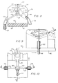
- FIGS. 1, 2, 3 and 4 there is there shown a drag probe mechanism that is adjustable by the skier between predetermined limits of probe depth, ranging from zero probe depth at which no auxiliary drag is imposed on the skis, to a maximum probe depth useful for the novice skier just learning to traverse the steeper slopes.
- the ski 13 is provided with a running surface 14 and a top surface 16 on which is fixedly supported in a manner which will hereinafter be explained the drag probe mechanism designated generally by the numeral 17.
- the drag probe mechanism includes a base member 18, conveniently fabricated from an injection molded plastic or an appropriate metal, to provide a recessed center section designated generally by the numeral 19, and formed by a relatively thin plate-like section 21 having raised marginal portions 22 and 23 on opposite sides of a plane vertical to the top surface 16 of the ski and generally coincident with the longitudinal axis 24 of the ski.
- the raised marginal portions 22 and 23 are provided with inner peripheral wall sections 26 that conform generally to the exterior configuration of the toe piece that is conventionally fixedly secured to the top surface of the ski to retain the skier's boot clamped to the ski.
- the toe piece is not illustrated. It should be understood however that the toe piece is fastened to the top surface of the ski by a pair of screws that penetrate the screw holes 27 formed in the member 21, and that the flat thin plate-like member 21 underlies the toe piece, and is securely clamped to the top surface 16 of the ski by the same screws that penetrate the screw holes 27 and which retain the toe piece in place.
- the base member 18, at its forward end is provided with upwardly extending bearing blocks 28 and 29, these being preferably integral with the base member 18, but possibly being separate components that are fixed to the base member by any appropriate means that will insure their retention on the base member.
- the bearing blocks 28 and 29 form journals for the pivot pins 31 and 32, the shank portions 33 of which provide bearing surfaces for the laterally opposed arms 34 and 36 connected at their forward ends by a front cross member 37 provided with a centrally disposed thickened portion 38 as viewed in FIG.
- a skier may insert the end of a ski pole into the yoke recess 39 and by appropriate forward or backward movement, impose a turning moment on the arms 34 and 36 about the axially aligned pivot pins 31 and 32, concomitantly causing the detent ball 41 to rest in a selected one of a series of shallow depressions formed on the inside surface of the arm 36.
- a forwardly directed force exerted on a ski pole engaged in the yoke recess 39 and aligned with the central axis 48 of that recess will cause the arm 36 to pivot clockwise about the pivot pin 32 while the ball 41 rides up on the inner surface 49 of the arm 36 between the recess 51 in which it is located in FIG. 2, prior to the ball dropping into the next successive recess 52.
- Continued pressure in the direction of the arrow causes the ball to be displaced from the recess 52, rise up on the surface 49 again and then fall into the third recess 53.
- the purpose of being able to pivot the yoke arms 34 and 36 as discussed above is to enable the height adjustment of the rearwardly projecting arm portions 34′ and 36′, so as to position the drag probe designated generally by the numeral 54, one each of which is threadably mounted in the rearwardly extending portions 34′ and 36′ as illustrated in FIGS. 1, 2, and 3.
- the drag probe 54 is provided with a head portion 56, a shank portion 57 threadably engaged in the rearwardly projecting arm portions 34 and 36, and a cylindrical control or drag portion 58 adapted to project below the lower running surface 14 of the ski as illustrated in FIG. 2, or to be elevated into the disengaged position illustrated in broken lines in FIG. 2 when force is applied in the direction of the arrow by proper manipulation of a ski pole engaged in the recess 39.
- the probe 54 have a rearwardly directed cant as illustrated in FIG. 2, so that as the ski moves forwardly over the snow in the direction indicated by the arrow, the forwardly facing surfaces 59 of the probe portion 58 in contact with the snow, being inclined to the direction of movements, develops a component of lift which is beneficial in the operation of the device.
- the laterally spaced pair of probes 54 are positioned in relation to the toe piece such that it places the probes near the skier's center of gravity. This is desirable to provide a desired neutral lateral stability characteristic.
- Locating the probes aft of the skier's center of gravity i.e., a positive stability margin as in the classic loose ski brake
- Locating the probes forward of the center of gravity would make the skis rotationally unstable.
- the probes in this embodiment are located or positioned about the middle of the toe piece which is the natural location of the skier's center of gravity when leaning slightly forward. The skier can control his center of gravity location by appropriate body motion and thereby control the stability characteristics of his skis.
- FIGS. 1 through 3 The shape and orientation of the probes are important factors in establishing the operating characteristics of the device.
- the basic design illustrated in FIGS. 1 through 3 features rearwardly canted cylindrical pins.
- vertical pins produce no lift, which is an advantage for the beginning skier. Rotating the skis about their longitudinal axis to produce drag on one side of the ski or the other does not require any force to overcome the lift component produced by a canted probe. This is particularly important for the snow-plow maneuver, and less important for the turning by leaning maneuver. Additionally, vertical pins provide higher drag, and therefore slower speeds, under poor snow conditions.
- a slightly backwardly canted probe is believed to be more appropriate for advanced skiers.
- the cant reduces the drag coefficient parallel to the skis without significantly changing the drag coefficient perpendicular to the skis. These characteristics would mean less steady state drag with the same turning ability due to the high drag perpendicular to the skis.
- the lift produced on icy snow would reduce the penetration depth and reduce the drag parallel to the skis without affecting turning ability. Because of the reduced drag parallel to the skis, the acceleration rate of the skis is increased, resulting in reaching the velocity-ability level of the skier in a shorter time frame, which is more apt to be handled expertly by the advanced skier.
- the drag probe embodiment illustrated in FIGS. 1 through 3 is configured to function either as an add-on unit to existing toe pieces, or as a configuration that could be integrated physically and functionally with a toe piece mechanism in one composite unit.
- FIGS. 5 through 7 there is there shown schematically a drag probe mechanism designated generally by the numeral 61 and mounted on the top surface 62 of a ski 63 having a lower running surface 64 adapted to run on the snow.
- the drag probe assembly 61 includes a body portion 66 on opposite sides of which are mounted probe assemblies 67 and 68 each probe 67 and 68 including a slide bearing 69 through which the probes are adapted to slide, with slidable movement of each of the probes being imparted by a toggle mechanism designated generally by the numeral 71 upon actuation of an actuation lever 72 by insertion of the end of the ski pole into the recess 73 of the actuation lever.
- the toggle mechanism 71 and actuating lever 72 work in conjunction with levers 74 and 76 suitably pivoted to the associated drag probes by appropriate pins 77 as illustrated, the associated ends of the levers 74 and 76 being slotted to accommodate axial displacement of the pivot pins 77 in relation to the associated levers when the levers are pivoted from one position to another.
- the levers 74 and 76 are adjustably connected to a common shaft 77, each end of which carries a vernier assembly designated generally by the numeral 79, and to which the associated levers 74 and 76 are pivotally connected.
- Vernier assembly 79 includes a coil compression spring 81 captured in the housing 82 having a recess 83 within which there is disposed for axial displacement therein a toothed ring 84 mounted fixedly on the shaft 78 and having teeth 86 adapted to mesh with complementary teeth 87 formed in the housing recess.
- a toothed ring 84 mounted fixedly on the shaft 78 and having teeth 86 adapted to mesh with complementary teeth 87 formed in the housing recess.
- the knob is then released and the teeth 86 and 87 are permitted to reengage, whereupon rotation of the shaft 78 by the actuation handle 72 will effect simultaneous axial translation of the probe 68 to either engage or disengage that portion 91 of the probe projecting below the lower surface 64 of the ski and engaging the snow to whatever depth is individually determined to be optimal by adjustment of the vernier knob 88.
- the drag probe portion 91 that extends below the lower surface 64 of the ski is canted rearwardly for the same reasons explained in connection with the embodiment of the invention illustrated in FIGS. 1 through 3.
- each ski 92 is equipped with a drag probe mechanism designated generally by the numeral 93, and each drag probe mechanism comprises a base member 94 adapted to be bolted or otherwise secured to the top surface 96 of the ski, and to support in actuating position thereon, a left probe 97 and a right probe 98 as viewed in FIG. 8.
- Both probes 97 and 98 are adapted to be actuated simultaneously in such manner as to either extend below the lower surface 99 of the ski 92 (full lines), or to be elevated to a position as illustrated in broken lines on the right of FIG. 8 in which the probe is shown retracted out of contact with the snow on which the ski is adapted to run.
- each of the probes 97 and 98 there is provided for each a bearing tube 101 and 102, respectively, the bearing tubes 101 and 102 being curved as illustrated, as are the associated probes.
- the probes 97 and 98 are connected by links 103 and 104 with a slide assembly designated generally by the numeral 106 and including for each of the links 103 and 104 a slide-bearing subassembly 107.
- Mounted on the slide bearing 107 is a cross-member 109 connected axially by a shaft 113 adapted to be selectively slid forwardly or backwardly by the toggle mechanism designated generally by the numeral 114 and illustrated in FIGS. 9 and 10.
- the toggle mechanism 114 is actuated by an actuation lever 116 having an aperture 117 therein adapted to be engaged by the lower end of the ski pole.
- the actuating handle 116 is pivoted by a pivot pin 118 so that when the actuating handle 116 is displaced vertically as illustrated in FIG. 9, the toggle mechanism 114 functions to switch the probes 97 and 98 from either a fully extended position or a fully retracted position to the opposite condition.
- Individualized adjustment of the two probes 97 and 98 is effected by individual adjustment of the screws 119 and 120 as shown in FIG. 10.
- FIGS. 11 through 13 there is there shown a laterally rotating probe structure designated generally by the numeral 121, the probe assembly being suitably mounted on the top surface 122 of a snow ski 123 having a lower surface 124 adapted to run on the snow.
- the laterally rotating probe assembly 121 is suitably mounted on a base member 126 secured to the upper surface 122 of the ski by any suitable means, and provides a slide bearing for a ski-pole-actuated slider member 127 having an aperture 128 therein through which the ski pole may be inserted to effect sliding movement of the slider member 127 in the direction of the arrows.
- the forwardly projecting lip 129 on the body member 126 is provided with a groove 130 into which the end of the ski pole may be inserted and which functions as an abutment against which the end of the ski pole may react when the top end of the ski pole in the hand of the skier is moved forward or backward to impose a sliding force on the slider 127.
- the slider is provided with linkage designated generally by the numeral 131 and including linkage members 132 and 133, both of which are attached to the upper end of associated drag probe 134.
- linkage members 132 and 133 both of which are attached to the upper end of associated drag probe 134.
- the link 133 imposes a vertically directed component of force on the drag probe 134, pivoting about the pin 136, and the link 132 also pivots about pivot pin 137.
- This motion causes the drag probe 134 to be elevated until its lower end 138 clears the bottom surface 124 of the ski, at which point it no longer functions to provide drag.
- the link 133 is further connected by a link 139 to the slider 127 so that the linkage 131 responds to sliding movement of the slider 127 in either direction.
- the alternate positions of the slider 127 are illustrated in FIG. 13.
- the single probe assembly 146 may include a housing 147 having a top wall 148 having an aperture 149 therethrough normally closed by a spring-loaded closure plate 151.
- the aperture 149 provides access for the lower end of the ski pole 152 which when pressed against the spring-pressed closure plate 151, shifts it into open position as illustrated, permitting the lower end of the ski pole 152 to pass downwardly through the housing 147 to engage the latching-type drag probe sub-assembly 153 as will hereinafter be explained.
- the drag probe sub-assembly 153 comprises a cylindrical insert 154, fabricated from any suitable material such as metal or plastic, and preferably associated as part of the toe piece, and providing a tapered opening 156 in the top end thereof, with the bottom end portion 157 of the insert being securely fastened in an appropriate aperture 158 formed in the ski.
- the insert 154 is provided with a shoulder 159 adjacent its upper end, just below the tapered opening 156, and at its lower end is provided with a seat 160 to receive a coiled compression spring 161 adapted to underlie an annular nut 162 through the center of which is threaded the drag probe 163.
- the coil compression spring 161 is compressed and normally biases the nut 162 and the probe 163 upwardly into the position illustrated in broken lines.
- movement of the nut 162 in this direction is impeded by a spring latch 164 arranged to pivot counterclockwise to release the nut 162 so as to permit the coil compression spring 161 to effect axial translation of the drag probe 163 into a retracted position.
- Tripping of the latch 164 may be effected by depressing the outer end 166 of a latch lever 167 by placing the bottom end of the ski pole 152 against the latch lever extension 166 and pressing downwardly thereon. As will be seen from FIG. 14, this causes the latch 164 to pivot counterclockwise, releasing the nut 162 so as to enable axial translation upwardly of the drag probe 163 into its retracted position.
- ski pole 152 be inserted into the aperture 149, pushing aside the closure plate 151, and pressing downwardly on the nut 162.
- the peripheral edge of the nut engages the latch 164, performing a camming action thereon, causing it to retract against the resilient bias tending to keep it latched, until the top surface of the nut 162 passes below the latch, at which time the latch will be be biased into a latching condition as illustrated in full lines and the probe will then be retained in an extended position.
- the ski pole may now be withdrawn and used for its conventional purpose.
- the obvious advantage to such a "penetration" configuration is that it enables more compact packaging of the drag probe mechanism in relation to the ski.
- the disadvantages are believed to outweigh the advantages, and it is therefore preferred that the double probe system be employed so as to embrace the ski, with no penetration of the ski by the probe.
- One of the disadvantages of re-designing the double probe system as illustrated in FIGS. 1 through 13 so that the drag probes penetrate the ski is that pairs of holes would have to be bored through the ski, creating a weakness in the ski which would of course require reinforcement. Additionally, the pairs of drag probes would have to be placed closer to the centerline of the ski, bringing the drag probes closer together, and this would effect a reduction in the turning moment generated in the ski as compared to probes spaced from the lateral edges of the ski.
Landscapes
- Road Paving Structures (AREA)
- Footwear And Its Accessory, Manufacturing Method And Apparatuses (AREA)
- Lubrication Of Internal Combustion Engines (AREA)
- Valve Device For Special Equipments (AREA)
- Valve-Gear Or Valve Arrangements (AREA)
Claims (8)
- Ski (13; 63; 92; 123; 140) mit einem an einer oberen Skifahrerträgerfläche (16; 62; 96; 122; 141) befestigten Skistiefelanbringungszehenstück und einer an der oberen Skifahrerträgerfläche (16; 62; 96; 122; 141) angebrachten Steueranordnung (17; 61; 93; 121; 146),
gekennzeichnet durch
wenigstens einen eine Steuerfläche aufweisenden stiftförmigen Steuerdorn (58; 91; 97; 98; 134; 163), der im wesentlichen nahe dem Zehenstück angebracht ist, in Kombination mit Mitteln (34, 36; 74, 76; 103, 104; 133, 139; 162, 164) zum wahlweisen Ausfahren des Steuerdorns (58; 91; 97; 98; 134; 163) zum Eindringen in den Schnee, damit ein bergab fahrender Skifahrer durch Ausübung herkömmlicher Körperbewegungen Hilfssteuerkräfte auf den Ski (13; 63; 92; 123; 140) ausüben kann, wenn sich dieser relativ zu dem Schnee bewegt, um durch Bremswirkung eine verbesserte Steuerung und eine verbesserte Manövrierbarkeit zu erlangen. - Ski (13; 63; 92; 123; 140) nach Anspruch 1, dadurch gekennzeichnet, daß der wenigstens eine Steuerdorn (58; 91; 97; 98; 134; 163) zylindrisch ist.
- Ski (13; 63; 92; 123; 140) nach Anspruch 1 oder Anspruch 2, gekennzeichnet durch Mittel (57; 79; 119; 120; 168) zum einstellbaren Anbringen des wenigstens einen Steuerdorns (58; 91; 97; 98; 163) an dem Ski (13; 63; 92; 140) zum Eindringen in den Schnee in verschiedene Tiefen, wodurch unterschiedliche Bremskräfte auf den Ski (13; 63; 92; 123; 140) einwirken können.
- Ski (13; 63; 92; 123; 140) nach einem der Ansprüche 1 bis 3, gekennzeichnet durch zwei Steuerdorne (58; 91; 97; 98; 134) zur Anordnung nahe gegenüberliegender Längsseitenflächen des Skis (13; 63; 92; 123).
- Ski (13; 63; 92; 123; 140) nach einem der Ansprüche 1 bis 3, gekennzeichnet durch einen einzelnen Steuerdorn (163) zur Anordnung an der Längsachse des Skis (140).
- Ski (13; 63; 92; 123; 140) nach Anspruch 4, gekennzeichnet durch ein Joch (34, 36, 37), das an einer an der oberen Skifahrerträgerfläche (16) zu befestigenden Basis (18) zum Tragen der Steuerdorne (58) schwenkbar angebracht ist, und Mittel (38) zur Handhabung durch einen Skifahrer zum Einstellen der Position des Jochs (34, 36, 37) und hierdurch der Steuerdorne (58) relativ zu der Fahrfläche (14) des Skis (13).
- Ski (13; 63; 92; 123; 140) nach Anspruch 6, gekennzeichnet durch Mittel (41, 42, 43) zur betriebsmäßigen Anordnung zwischen dem Joch (34, 36, 37) und dem Ski (13) zum federnden Halten des Jochs (34, 36, 37) und der Steuerdorne (58) in der eingestellten Position.
- Ski (13; 63; 92; 123; 140) nach einem der Ansprüche 1 bis 7, dadurch gekennzeichnet, daß der wenigstens eine Steuerdorn (58) durch ein Gewinde (57) angebracht ist, so daß er mehr oder weniger in den Schnee relativ zur Fahrfläche (14) des Skis (13) vorstehend eingestellt werden kann.
Applications Claiming Priority (2)
| Application Number | Priority Date | Filing Date | Title |
|---|---|---|---|
| US12621187A | 1987-11-27 | 1987-11-27 | |
| US126211 | 1987-11-27 |
Publications (3)
| Publication Number | Publication Date |
|---|---|
| EP0318041A2 EP0318041A2 (de) | 1989-05-31 |
| EP0318041A3 EP0318041A3 (de) | 1991-04-10 |
| EP0318041B1 true EP0318041B1 (de) | 1995-03-08 |
Family
ID=22423602
Family Applications (1)
| Application Number | Title | Priority Date | Filing Date |
|---|---|---|---|
| EP88119704A Expired - Lifetime EP0318041B1 (de) | 1987-11-27 | 1988-11-25 | Vorrichtung zur Kontrolle der Abfahrtskigeschwindigkeit und der Abfahrtskimanövrierbarkeit |
Country Status (3)
| Country | Link |
|---|---|
| EP (1) | EP0318041B1 (de) |
| AT (1) | ATE119414T1 (de) |
| DE (1) | DE3853264D1 (de) |
Family Cites Families (4)
| Publication number | Priority date | Publication date | Assignee | Title |
|---|---|---|---|---|
| US3580605A (en) * | 1969-10-29 | 1971-05-25 | Nathan Shreve Spitler | Hydraulic steering and braking system for snow skis |
| AT332272B (de) * | 1974-08-12 | 1976-09-27 | Schultes Ing Hermann | Einrichtung an skiern |
| CH629108A5 (en) * | 1981-04-25 | 1982-04-15 | Hubert Inderbitzin | Control wings for skiers |
| AT371728B (de) * | 1981-06-24 | 1983-07-25 | Schmid Irmtraud | Ski |
-
1988
- 1988-11-25 AT AT88119704T patent/ATE119414T1/de not_active IP Right Cessation
- 1988-11-25 EP EP88119704A patent/EP0318041B1/de not_active Expired - Lifetime
- 1988-11-25 DE DE3853264T patent/DE3853264D1/de not_active Expired - Lifetime
Also Published As
| Publication number | Publication date |
|---|---|
| EP0318041A2 (de) | 1989-05-31 |
| DE3853264D1 (de) | 1995-04-13 |
| ATE119414T1 (de) | 1995-03-15 |
| EP0318041A3 (de) | 1991-04-10 |
Similar Documents
| Publication | Publication Date | Title |
|---|---|---|
| US4084831A (en) | Skateboard with control unit | |
| US4007946A (en) | Short ski | |
| US3944237A (en) | Ski binding | |
| US5766051A (en) | Wakeboard traction pad | |
| US20020017771A1 (en) | Multi-purpose combination snowshoe/ski | |
| US4508364A (en) | Ski pole | |
| US4952184A (en) | Cross-water ski | |
| US4995631A (en) | Mono-ski deep side cuts for user stability control | |
| US3087173A (en) | Retractable water ski fin | |
| US3645347A (en) | Guide means for skis | |
| US4986561A (en) | Method and apparatus for speed and maneuverability control for downhill skiing | |
| US4289325A (en) | Skateboard | |
| EP0471675B1 (de) | Abfahrtsski mit integrierter sondeneinheit | |
| US4804345A (en) | Equipment for towless skiing on water surface | |
| US20020011727A1 (en) | Ski rocker training device | |
| US5277141A (en) | Ice and snow surf-board | |
| US3015830A (en) | Water skis | |
| EP0318041B1 (de) | Vorrichtung zur Kontrolle der Abfahrtskigeschwindigkeit und der Abfahrtskimanövrierbarkeit | |
| US3123373A (en) | Flexible ski-sled | |
| US4349209A (en) | Snow shuttle | |
| US6626443B2 (en) | Retractable guide means for a snowboard | |
| US3580605A (en) | Hydraulic steering and braking system for snow skis | |
| US4844502A (en) | Monoski binding arrangement | |
| US5145200A (en) | Universal integral ski control system | |
| US3992789A (en) | Forward releasing snow ski boot |
Legal Events
| Date | Code | Title | Description |
|---|---|---|---|
| PUAI | Public reference made under article 153(3) epc to a published international application that has entered the european phase |
Free format text: ORIGINAL CODE: 0009012 |
|
| 17P | Request for examination filed |
Effective date: 19881125 |
|
| AK | Designated contracting states |
Kind code of ref document: A2 Designated state(s): AT CH DE FR IT LI SE |
|
| PUAL | Search report despatched |
Free format text: ORIGINAL CODE: 0009013 |
|
| RHK1 | Main classification (correction) |
Ipc: A63C 5/06 |
|
| AK | Designated contracting states |
Kind code of ref document: A3 Designated state(s): AT CH DE FR IT LI SE |
|
| 17Q | First examination report despatched |
Effective date: 19921006 |
|
| GRAA | (expected) grant |
Free format text: ORIGINAL CODE: 0009210 |
|
| AK | Designated contracting states |
Kind code of ref document: B1 Designated state(s): AT CH DE FR IT LI SE |
|
| PG25 | Lapsed in a contracting state [announced via postgrant information from national office to epo] |
Ref country code: IT Free format text: LAPSE BECAUSE OF FAILURE TO SUBMIT A TRANSLATION OF THE DESCRIPTION OR TO PAY THE FEE WITHIN THE PRE;WARNING: LAPSES OF ITALIAN PATENTS WITH EFFECTIVE DATE BEFORE 2007 MAY HAVE OCCURRED AT ANY TIME BEFORE 2007. THE CORRECT EFFECTIVE DATE MAY BE DIFFERENT FROM THE ONE RECORDED.SCRIBED TIME-LIMIT Effective date: 19950308 Ref country code: AT Effective date: 19950308 Ref country code: CH Effective date: 19950308 Ref country code: LI Effective date: 19950308 |
|
| REF | Corresponds to: |
Ref document number: 119414 Country of ref document: AT Date of ref document: 19950315 Kind code of ref document: T |
|
| REF | Corresponds to: |
Ref document number: 3853264 Country of ref document: DE Date of ref document: 19950413 |
|
| PG25 | Lapsed in a contracting state [announced via postgrant information from national office to epo] |
Ref country code: SE Effective date: 19950608 |
|
| PG25 | Lapsed in a contracting state [announced via postgrant information from national office to epo] |
Ref country code: DE Effective date: 19950609 |
|
| REG | Reference to a national code |
Ref country code: CH Ref legal event code: PL |
|
| ET | Fr: translation filed | ||
| PLBE | No opposition filed within time limit |
Free format text: ORIGINAL CODE: 0009261 |
|
| STAA | Information on the status of an ep patent application or granted ep patent |
Free format text: STATUS: NO OPPOSITION FILED WITHIN TIME LIMIT |
|
| 26N | No opposition filed | ||
| PGFP | Annual fee paid to national office [announced via postgrant information from national office to epo] |
Ref country code: FR Payment date: 20061108 Year of fee payment: 19 |
|
| REG | Reference to a national code |
Ref country code: FR Ref legal event code: ST Effective date: 20080930 |
|
| PG25 | Lapsed in a contracting state [announced via postgrant information from national office to epo] |
Ref country code: FR Free format text: LAPSE BECAUSE OF NON-PAYMENT OF DUE FEES Effective date: 20071130 |