EP0471323B1 - Flüssigkeitsvernebler für Medikamente - Google Patents
Flüssigkeitsvernebler für Medikamente Download PDFInfo
- Publication number
- EP0471323B1 EP0471323B1 EP91113500A EP91113500A EP0471323B1 EP 0471323 B1 EP0471323 B1 EP 0471323B1 EP 91113500 A EP91113500 A EP 91113500A EP 91113500 A EP91113500 A EP 91113500A EP 0471323 B1 EP0471323 B1 EP 0471323B1
- Authority
- EP
- European Patent Office
- Prior art keywords
- nozzle
- nebulizer
- nebulizer according
- annular gap
- tip
- Prior art date
- Legal status (The legal status is an assumption and is not a legal conclusion. Google has not performed a legal analysis and makes no representation as to the accuracy of the status listed.)
- Expired - Lifetime
Links
- 239000003814 drug Substances 0.000 title claims abstract description 8
- 239000007788 liquid Substances 0.000 title claims description 22
- 238000002664 inhalation therapy Methods 0.000 claims abstract description 5
- 239000006199 nebulizer Substances 0.000 claims description 26
- 238000002663 nebulization Methods 0.000 claims description 4
- 230000015572 biosynthetic process Effects 0.000 claims 1
- 238000009434 installation Methods 0.000 claims 1
- 229940079593 drug Drugs 0.000 abstract description 6
- 239000002245 particle Substances 0.000 description 7
- 239000000443 aerosol Substances 0.000 description 6
- 230000000694 effects Effects 0.000 description 4
- 230000000241 respiratory effect Effects 0.000 description 2
- 241000475481 Nebula Species 0.000 description 1
- 238000000889 atomisation Methods 0.000 description 1
- 230000005611 electricity Effects 0.000 description 1
- 238000004519 manufacturing process Methods 0.000 description 1
- 230000001105 regulatory effect Effects 0.000 description 1
- 208000023504 respiratory system disease Diseases 0.000 description 1
- 230000001225 therapeutic effect Effects 0.000 description 1
- 238000002560 therapeutic procedure Methods 0.000 description 1
Images


Classifications
-
- B—PERFORMING OPERATIONS; TRANSPORTING
- B05—SPRAYING OR ATOMISING IN GENERAL; APPLYING FLUENT MATERIALS TO SURFACES, IN GENERAL
- B05B—SPRAYING APPARATUS; ATOMISING APPARATUS; NOZZLES
- B05B7/00—Spraying apparatus for discharge of liquids or other fluent materials from two or more sources, e.g. of liquid and air, of powder and gas
- B05B7/0012—Apparatus for achieving spraying before discharge from the apparatus
Definitions
- the invention relates to a nebulizer device for the Nebulization of watery or oily medication at the Inhalation therapy with the characteristics of the generic term of the Claim 1.
- a nebulizer device with these features is known from EP-A-0 261 649.
- the atomizing nozzle is in one Inhalation therapy device integrated and in the bottom of a Storage container for the liquid arranged.
- the Atomizer nozzle works on the Venturi principle and has plus a nozzle body with a nozzle opening at the top has that of a concentric, annular gap is surrounded.
- the nozzle body also has channels through which the liquid from the reservoir to the ring-shaped Gap is suckable.
- Embodiments adjusting means provided the distance adjustable between the surface and the nozzle openings do.
- a nebulizer with a Venturi principle working nozzle is also known from EP-A-0 170 715. At This nozzle is next to the compressed gas channel arranged opposite two intake ducts. The Across from the nozzle openings is a air flow control extending the nozzle with a wedge-shaped Bottom.
- nebulizers from US 3,762,409 and AU-B-483 193 are nebulizers with a mixing chamber, i.e. with a closed room above the compressed air nozzle opening in which the drug is sucked in and already partially nebulized. From the The aspirated medication joins the mixing chamber Compressed gas flow from a further opening that the Opposed nozzle opening for the compressed gas and which differs from outside as the only nozzle opening.
- These nebulizers differ from the nebulizers described above due to the mixing chamber and due to the fact that after a nozzle opening appears on the outside.
- nebulizers The different designs of the previously described The aim of nebulizers is always the best, i.e. to produce respiratory aerosol.
- the invention also has the object to improve a liquid nebulizer so that Optimal particle sizes in the sense of fine atomization can be achieved.
- a defined amount is one Inhale medication.
- a maximum is achieved by the invention
- the drug is nebulized so that the inhalation time is minimized.
- Another Advantage of the invention is that the liquid through channels and thus regulated the gap is fed.
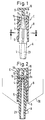
- the liquid nebulizer shown in Figures 1 and 2 is part of a Handheld devices for inhalations.
- the liquid nebulizer is inside a two-part housing, of which in Fig. 2 the reservoir 20 for the Liquid is shown.
- the housing (otherwise not shown) faces below a hose for the supply of compressed air (not shown) and a top Mouthpiece (not shown) and is also with a known nebulizer button (not shown) equipped, at the pressure of which compressed air is actuated.
- the liquid nebulizer consists of three parts, namely the nozzle body A, the Cylinder sleeve B and the attachment C. These parts are made by simple plug connections connected with each other.
- the nozzle body A which is shown in FIG. 4, points downwards directed nozzle body extension 21 to which a compressed air line is connected becomes. In the area of the nozzle body extension 21, the nozzle body A is sealed passed through the bottom of the reservoir 20.
- the nozzle body A has a central, through the entire nozzle body in Nozzle channel 1 running in the longitudinal direction.
- the upper section of the Nozzle body A is in the form of a nozzle cone 4 with a nozzle tip 3 executed.
- nozzle tip 3 In the middle of the nozzle tip 3, which is cylindrical on the outside, sits Nozzle opening 2.
- the nozzle body A has ribs 5 on the outside, which together with the inner wall of the cylinder sleeve B form channels 7 in which the liquid is sucked from the reservoir to the gap 2a.
- the cylinder sleeve B shown in FIGS. 5 and 6 has an outer cylinder surface 9.
- the cylinder thus formed goes over a shoulder in the nozzle jacket 8 smaller diameter over.
- the top of the Nozzle jacket is designed as a depression 14.
- the cylinder ring 12 forms together with the nozzle tip 3 an annular gap 2a which the nozzle opening 2 with Distance concentrically surrounds.
- the cylinder sleeve B ends at the bottom somewhat above the bottom of the storage container 20 so that an annular gap 6 is formed.
- the attachment C has a cylinder 15 at the bottom, the wall thickness of which Dimension of the formed between the outer cylinder surface 9 and the nozzle jacket 8 Paragraph corresponds.
- the cylinder 15 is provided with a baffle plate 16 via webs 19 connected.
- the baffle plate 16 has a center against the nozzle opening 2 directed pin 17, which has a conical tip 18.
- the height of the cylinder 15 is dimensioned so that its in the installed state Top is higher than the top of the nozzle shell 8.
- the top of the Cylinder 15 is approximately at the height of the tip 18, the maximum distance is 0.2 mm.
- the described device works as follows: If compressed air is passed through the nozzle channel 1, a negative pressure is created at the nozzle opening 2. The air is also swirled by deflecting the emerging air at the tip 18 of the pin 17 and at the baffle plate 16.
Landscapes
- Nozzles (AREA)
- Dental Tools And Instruments Or Auxiliary Dental Instruments (AREA)
- Pharmaceuticals Containing Other Organic And Inorganic Compounds (AREA)
- Medicinal Preparation (AREA)
- Medicines Containing Plant Substances (AREA)
Description
Es zeigt:
Wird Druckluft durch den Düsenkanal 1 geleitet, dann entsteht an der Düsenöffnung 2 ein Unterdruck. Durch das Ablenken der austretenden Luft an der Spitze 18 des Stiftes 17 und an der Prallplatte 16 wird die Luft außerdem verwirbelt.
Claims (10)
- Verneblervorrichtung für die Verneblung wässriger oder öliger Medikamente bei der Inhalationstherapie mit einer Zerstäuberdüse für den Austritt von Druckluft, wobei diese Verneblervorrichtung für den Einbau in ein zweiteiliges Verneblungsgerät angepaßt ist, dessen unterer Teil einen Vorratsbehälter (20) für die Flüssigkeit aufweist, durch dessen Boden abgedichtet die nach dem Venturi-Prinzip arbeitende Verneblervorrichtung geführt ist, mit einem Düsenkörper (A), der am oberen Ende eine Düsenöffnung (2) aufweist, die von einem konzentrischen, ringförmigen Spalt (2a) umgeben ist, und der Kanäle (7) aufweist, über die die Flüssigkeit aus dem Vorratsbehälter zum Spalt (2a) ansaugbar ist,
dadurch gekennzeichnet, daß
gegenüber der Düsenöffnung (2) mit Abstand zu dieser eine Prallplatte (16) angeordnet ist, die einen gegen die Düsenöffnung (2) gerichteten Stift (17) mit kegelförmiger Spitze (18) trägt. - Vernebler nach Anspruch 1, dadurch gekennzeichnet, daß der ringförmige Spalt (2a) von der Düsenspitze (3) und einem Düsenmantel (8) gebildet ist und daß der Düsenmantel (8) den oberen Teil einer den Düsenkörper (A) umgebende Zylinderhülse (B) bildet.
- Vernebler nach Anspruch 2, dadurch gekennzeichnet, daß die Zylinderhülse (B) unter Bildung eines unteren, als Zugangsöffnung zum Vorratsbehälter (20) dienenden Ringspalts (6) auf äußeren Rippen (5) des Düsenkörpers (A) sitzt und daß durch die Rippen (5) und die Innenwand der Zylinderhülse (B) die zum ringförmigen Spalt (2a) führenden Kanäle (7) gebildet sind.
- Vernebler nach einem der Ansprüche 1 bis 3, dadurch gekennzeichnet, daß der Durchmesser des Stiftes (17) dem Außendurchmesser des ringförmigen Spalts (2a) entspricht.
- Vernebler nach einem der Ansprüche 2 bis 4, dadurch gekennzeichnet, daß die Oberseite des Düsenmantels (8) als Senke (14) ausgebildet ist, deren tiefster Punkt in der Ebene der Düsenöffnung (2) oder darüber liegt.
- Vernebler nach einem der Ansprüche 2 bis 5, dadurch gekennzeichnet, daß auf der Zylinderhülse (B) ein Zylinder (15) sitzt, der über Stege (19) mit der Prallplatte (16) verbunden ist und mit dieser eine Einheit (Aufsatz C) bildet.
- Vernebler nach Anspruch 6, dadurch gekennzeichnet, daß die Oberkante des Zylinders (15) in einem maximalen Abstand von 0,2 mm von der Spitze (18) des Stiftes (17) angeordnet ist.
- Vernebler nach einem der Ansprüche 1 bis 7, dadurch gekennzeichnet, daß der die Spitze (18) bildende Kegel einen Spitzenwinkel von 140-160° hat.
- Vernebler nach einem der Ansprüche 1 bis 8, dadurch gekennzeichnet, daß der Boden des Flüssigkeitsbehälters (20) zur Mitte hin abfällt.
- Vernebler nach einem der Ansprüche 1 bis 9, dadurch gekennzeichnet, daß er aus Kunststoffteilen zusammengesteckt ist.
Applications Claiming Priority (2)
| Application Number | Priority Date | Filing Date | Title |
|---|---|---|---|
| DE9011768U | 1990-08-13 | ||
| DE9011768U DE9011768U1 (de) | 1990-08-13 | 1990-08-13 | Flüssigkeitsvernebler für Medikamente |
Publications (2)
| Publication Number | Publication Date |
|---|---|
| EP0471323A1 EP0471323A1 (de) | 1992-02-19 |
| EP0471323B1 true EP0471323B1 (de) | 1999-12-01 |
Family
ID=6856490
Family Applications (1)
| Application Number | Title | Priority Date | Filing Date |
|---|---|---|---|
| EP91113500A Expired - Lifetime EP0471323B1 (de) | 1990-08-13 | 1991-08-12 | Flüssigkeitsvernebler für Medikamente |
Country Status (4)
| Country | Link |
|---|---|
| EP (1) | EP0471323B1 (de) |
| JP (1) | JPH04244168A (de) |
| AT (1) | ATE187084T1 (de) |
| DE (2) | DE9011768U1 (de) |
Cited By (2)
| Publication number | Priority date | Publication date | Assignee | Title |
|---|---|---|---|---|
| US7547292B2 (en) | 2001-01-11 | 2009-06-16 | Powderject Research Limited | Needleless syringe |
| US8540665B2 (en) | 2007-05-04 | 2013-09-24 | Powder Pharmaceuticals Inc. | Particle cassettes and processes therefor |
Families Citing this family (8)
| Publication number | Priority date | Publication date | Assignee | Title |
|---|---|---|---|---|
| GB9114080D0 (en) * | 1991-06-28 | 1991-08-14 | Weston Terence E | Atomising valve |
| DE9113446U1 (de) * | 1991-10-29 | 1992-01-16 | Kendall Medizinische Erzeugnisse GmbH, 8425 Neustadt | Handvernebler für das Zerstäuben von therapeutischen Flüssigkeiten |
| GB9311614D0 (en) * | 1993-06-04 | 1993-07-21 | Aid Medic Ltd | Nebulizer |
| US5875774A (en) * | 1996-01-05 | 1999-03-02 | Sunrise Medical Hhg Inc. | Nebulizer |
| CA2608310A1 (en) | 2005-06-29 | 2007-01-04 | Boehringer Ingelheim International Gmbh | Method and device for atomising liquid |
| US9757528B2 (en) | 2010-08-23 | 2017-09-12 | Darren Rubin | Nebulizer having different negative pressure threshold settings |
| WO2012026963A2 (en) | 2010-08-23 | 2012-03-01 | Darren Rubin | Systems and methods of aerosol delivery with airflow regulation |
| CN109172965B (zh) * | 2018-10-24 | 2024-09-13 | 威海盛洁医疗科技有限公司 | 一种雾化颗粒大小可调节的雾化杯 |
Family Cites Families (6)
| Publication number | Priority date | Publication date | Assignee | Title |
|---|---|---|---|---|
| DE100333C (de) * | ||||
| DE1006354B (de) * | 1954-03-19 | 1957-04-11 | Paul Tegtmeier | Fluessigkeitsbrause |
| US3762409A (en) * | 1970-11-03 | 1973-10-02 | V Lester | Nebulizer |
| AU483193B2 (en) * | 1975-12-03 | 1976-02-26 | Hudson Oxygen Therapy Sales Company | A nebulizer |
| ATE33447T1 (de) * | 1984-08-09 | 1988-04-15 | Brugger Inge | Zerstaeubervorrichtung. |
| ES2029248T3 (es) * | 1986-09-22 | 1992-08-01 | Omron Tateisi Electronics Co. | Pulverizador. |
-
1990
- 1990-08-13 DE DE9011768U patent/DE9011768U1/de not_active Expired - Lifetime
-
1991
- 1991-08-12 DE DE59109170T patent/DE59109170D1/de not_active Expired - Fee Related
- 1991-08-12 AT AT91113500T patent/ATE187084T1/de active
- 1991-08-12 JP JP3201769A patent/JPH04244168A/ja active Pending
- 1991-08-12 EP EP91113500A patent/EP0471323B1/de not_active Expired - Lifetime
Cited By (5)
| Publication number | Priority date | Publication date | Assignee | Title |
|---|---|---|---|---|
| US7547292B2 (en) | 2001-01-11 | 2009-06-16 | Powderject Research Limited | Needleless syringe |
| USRE43824E1 (en) | 2001-01-11 | 2012-11-20 | Powder Pharmaceuticals Inc. | Needleless syringe |
| US8540665B2 (en) | 2007-05-04 | 2013-09-24 | Powder Pharmaceuticals Inc. | Particle cassettes and processes therefor |
| US9044546B2 (en) | 2007-05-04 | 2015-06-02 | Powder Pharmaceuticals Incorporated | Particle cassettes and processes therefor |
| US9358338B2 (en) | 2007-05-04 | 2016-06-07 | Powder Pharmaceuticals Incorporated | Particle cassettes and processes therefor |
Also Published As
| Publication number | Publication date |
|---|---|
| ATE187084T1 (de) | 1999-12-15 |
| JPH04244168A (ja) | 1992-09-01 |
| DE9011768U1 (de) | 1990-11-08 |
| DE59109170D1 (de) | 2000-01-05 |
| EP0471323A1 (de) | 1992-02-19 |
Similar Documents
| Publication | Publication Date | Title |
|---|---|---|
| EP0540775B1 (de) | Vernebler insbesondere zur Anwendung in Geräten für die Inhalationstherapie | |
| DE69420186T2 (de) | Vernebler | |
| EP0170715B1 (de) | Zerstäubervorrichtung | |
| DE69936895T2 (de) | Vernebler | |
| DE19520622C2 (de) | Vorrichtung zum Vernebeln von Fluiden | |
| DE69633306T2 (de) | Beatmungskreis für einen zerstäuber | |
| DE69819017T2 (de) | Vernebelungskopf und Vernebelungsvorrichtung | |
| EP0786263B1 (de) | Vernebler | |
| DE69514986T2 (de) | Zerstäuber | |
| DE69810119T2 (de) | Atmungsbetätigter vernebler mit einer einen druckausgleichskolben aufweisenden ventileinrichtung | |
| DE69516792T2 (de) | Sprühdüse mit interner Luftmischung | |
| EP0610350B1 (de) | Handvernebler für das zerstäuben von therapeutischen flüssigkeiten | |
| EP0653218B1 (de) | Zerstäubervorrichtung | |
| DE69108559T2 (de) | Aerosolerzeuger zum liefern einer erhöhten atembaren fraktion. | |
| DE112012005500T5 (de) | Vernebler und Verneblerset | |
| EP0408786A1 (de) | Düsenkopf | |
| EP0471323B1 (de) | Flüssigkeitsvernebler für Medikamente | |
| DE19902844C1 (de) | Medikamentenvernebler mit verbessertem Prallschirm | |
| DE3238149A1 (de) | Vorrichtung zum zerstaeuben, verteilen, vermischen von fluessigkeiten | |
| DE69212143T2 (de) | Inhalator | |
| DE69824327T2 (de) | Inhalationsgerät | |
| DE10319582A1 (de) | Zweistoffsprühdüse | |
| DE69014891T2 (de) | Vorrichtung zum herstellen einer partikeldispersion. | |
| DE1046264B (de) | Zerstaeuber fuer medizinische Zwecke | |
| DE3429411A1 (de) | Zerstaeuberduese |
Legal Events
| Date | Code | Title | Description |
|---|---|---|---|
| PUAI | Public reference made under article 153(3) epc to a published international application that has entered the european phase |
Free format text: ORIGINAL CODE: 0009012 |
|
| AK | Designated contracting states |
Kind code of ref document: A1 Designated state(s): AT BE CH DE DK ES FR GB GR IT LI LU NL SE |
|
| 17P | Request for examination filed |
Effective date: 19920806 |
|
| 19A | Proceedings stayed before grant |
Effective date: 19930317 |
|
| 19F | Resumption of proceedings before grant (after stay of proceedings) |
Effective date: 19950302 |
|
| RAP1 | Party data changed (applicant data changed or rights of an application transferred) |
Owner name: PAUL RITZAU PARI-WERK GMBH |
|
| 17Q | First examination report despatched |
Effective date: 19950616 |
|
| RAP1 | Party data changed (applicant data changed or rights of an application transferred) |
Owner name: PARI GMBH SPEZIALISTEN FUER EFFEKTIVE INHALATION |
|
| GRAG | Despatch of communication of intention to grant |
Free format text: ORIGINAL CODE: EPIDOS AGRA |
|
| GRAG | Despatch of communication of intention to grant |
Free format text: ORIGINAL CODE: EPIDOS AGRA |
|
| GRAH | Despatch of communication of intention to grant a patent |
Free format text: ORIGINAL CODE: EPIDOS IGRA |
|
| GRAH | Despatch of communication of intention to grant a patent |
Free format text: ORIGINAL CODE: EPIDOS IGRA |
|
| GRAA | (expected) grant |
Free format text: ORIGINAL CODE: 0009210 |
|
| AK | Designated contracting states |
Kind code of ref document: B1 Designated state(s): AT BE CH DE DK ES FR GB GR IT LI LU NL SE |
|
| PG25 | Lapsed in a contracting state [announced via postgrant information from national office to epo] |
Ref country code: NL Free format text: LAPSE BECAUSE OF FAILURE TO SUBMIT A TRANSLATION OF THE DESCRIPTION OR TO PAY THE FEE WITHIN THE PRESCRIBED TIME-LIMIT Effective date: 19991201 Ref country code: SE Free format text: THE PATENT HAS BEEN ANNULLED BY A DECISION OF A NATIONAL AUTHORITY Effective date: 19991201 Ref country code: ES Free format text: THE PATENT HAS BEEN ANNULLED BY A DECISION OF A NATIONAL AUTHORITY Effective date: 19991201 Ref country code: FR Free format text: LAPSE BECAUSE OF FAILURE TO SUBMIT A TRANSLATION OF THE DESCRIPTION OR TO PAY THE FEE WITHIN THE PRESCRIBED TIME-LIMIT Effective date: 19991201 Ref country code: GR Free format text: LAPSE BECAUSE OF NON-PAYMENT OF DUE FEES Effective date: 19991201 Ref country code: GB Free format text: LAPSE BECAUSE OF FAILURE TO SUBMIT A TRANSLATION OF THE DESCRIPTION OR TO PAY THE FEE WITHIN THE PRESCRIBED TIME-LIMIT Effective date: 19991201 Ref country code: IT Free format text: LAPSE BECAUSE OF FAILURE TO SUBMIT A TRANSLATION OF THE DESCRIPTION OR TO PAY THE FEE WITHIN THE PRESCRIBED TIME-LIMIT;WARNING: LAPSES OF ITALIAN PATENTS WITH EFFECTIVE DATE BEFORE 2007 MAY HAVE OCCURRED AT ANY TIME BEFORE 2007. THE CORRECT EFFECTIVE DATE MAY BE DIFFERENT FROM THE ONE RECORDED. Effective date: 19991201 |
|
| REF | Corresponds to: |
Ref document number: 187084 Country of ref document: AT Date of ref document: 19991215 Kind code of ref document: T |
|
| REG | Reference to a national code |
Ref country code: CH Ref legal event code: EP |
|
| REF | Corresponds to: |
Ref document number: 59109170 Country of ref document: DE Date of ref document: 20000105 |
|
| PG25 | Lapsed in a contracting state [announced via postgrant information from national office to epo] |
Ref country code: DK Free format text: LAPSE BECAUSE OF FAILURE TO SUBMIT A TRANSLATION OF THE DESCRIPTION OR TO PAY THE FEE WITHIN THE PRESCRIBED TIME-LIMIT Effective date: 20000301 |
|
| REG | Reference to a national code |
Ref country code: CH Ref legal event code: NV Representative=s name: BUECHEL & PARTNER AG PATENTBUERO |
|
| EN | Fr: translation not filed | ||
| NLV1 | Nl: lapsed or annulled due to failure to fulfill the requirements of art. 29p and 29m of the patents act | ||
| GBV | Gb: ep patent (uk) treated as always having been void in accordance with gb section 77(7)/1977 [no translation filed] |
Effective date: 19991201 |
|
| PG25 | Lapsed in a contracting state [announced via postgrant information from national office to epo] |
Ref country code: AT Free format text: LAPSE BECAUSE OF NON-PAYMENT OF DUE FEES Effective date: 20000812 Ref country code: LU Free format text: LAPSE BECAUSE OF NON-PAYMENT OF DUE FEES Effective date: 20000812 |
|
| PG25 | Lapsed in a contracting state [announced via postgrant information from national office to epo] |
Ref country code: BE Free format text: LAPSE BECAUSE OF NON-PAYMENT OF DUE FEES Effective date: 20000831 Ref country code: CH Free format text: LAPSE BECAUSE OF NON-PAYMENT OF DUE FEES Effective date: 20000831 Ref country code: LI Free format text: LAPSE BECAUSE OF NON-PAYMENT OF DUE FEES Effective date: 20000831 |
|
| PLBE | No opposition filed within time limit |
Free format text: ORIGINAL CODE: 0009261 |
|
| STAA | Information on the status of an ep patent application or granted ep patent |
Free format text: STATUS: NO OPPOSITION FILED WITHIN TIME LIMIT |
|
| 26N | No opposition filed | ||
| BERE | Be: lapsed |
Owner name: PARI G.M.B.H. SPEZIALISTEN FUR EFFEKTIVE INHALATI Effective date: 20000831 |
|
| REG | Reference to a national code |
Ref country code: CH Ref legal event code: PL |
|
| PGFP | Annual fee paid to national office [announced via postgrant information from national office to epo] |
Ref country code: DE Payment date: 20030926 Year of fee payment: 13 |
|
| PG25 | Lapsed in a contracting state [announced via postgrant information from national office to epo] |
Ref country code: DE Free format text: LAPSE BECAUSE OF NON-PAYMENT OF DUE FEES Effective date: 20050301 |