EP0471007B1 - Absorption filter for color display devices - Google Patents
Absorption filter for color display devices Download PDFInfo
- Publication number
- EP0471007B1 EP0471007B1 EP90907670A EP90907670A EP0471007B1 EP 0471007 B1 EP0471007 B1 EP 0471007B1 EP 90907670 A EP90907670 A EP 90907670A EP 90907670 A EP90907670 A EP 90907670A EP 0471007 B1 EP0471007 B1 EP 0471007B1
- Authority
- EP
- European Patent Office
- Prior art keywords
- color
- areas
- elements
- filter
- primary
- Prior art date
- Legal status (The legal status is an assumption and is not a legal conclusion. Google has not performed a legal analysis and makes no representation as to the accuracy of the status listed.)
- Expired - Lifetime
Links
- 238000010521 absorption reaction Methods 0.000 title abstract description 12
- 239000000835 fiber Substances 0.000 claims description 34
- 239000003086 colorant Substances 0.000 claims description 21
- 239000000758 substrate Substances 0.000 claims description 21
- 238000000034 method Methods 0.000 claims description 14
- 230000003287 optical effect Effects 0.000 claims description 13
- 230000005540 biological transmission Effects 0.000 claims description 12
- 238000009826 distribution Methods 0.000 claims description 7
- 238000004519 manufacturing process Methods 0.000 claims description 6
- 238000001228 spectrum Methods 0.000 claims description 6
- 239000011521 glass Substances 0.000 claims description 5
- 239000011347 resin Substances 0.000 claims description 2
- 229920005989 resin Polymers 0.000 claims description 2
- 238000000059 patterning Methods 0.000 claims 7
- 239000011248 coating agent Substances 0.000 claims 3
- 238000000576 coating method Methods 0.000 claims 3
- 230000001681 protective effect Effects 0.000 claims 3
- 108010010803 Gelatin Proteins 0.000 claims 2
- 229920000159 gelatin Polymers 0.000 claims 2
- 239000008273 gelatin Substances 0.000 claims 2
- 235000019322 gelatine Nutrition 0.000 claims 2
- 235000011852 gelatine desserts Nutrition 0.000 claims 2
- 230000002745 absorbent Effects 0.000 claims 1
- 239000002250 absorbent Substances 0.000 claims 1
- 238000000151 deposition Methods 0.000 claims 1
- OAICVXFJPJFONN-UHFFFAOYSA-N Phosphorus Chemical compound [P] OAICVXFJPJFONN-UHFFFAOYSA-N 0.000 abstract description 27
- 239000004973 liquid crystal related substance Substances 0.000 abstract description 3
- 239000000463 material Substances 0.000 description 16
- 239000010410 layer Substances 0.000 description 8
- 230000000694 effects Effects 0.000 description 6
- 230000007935 neutral effect Effects 0.000 description 6
- 239000002245 particle Substances 0.000 description 4
- 238000010894 electron beam technology Methods 0.000 description 3
- 238000001914 filtration Methods 0.000 description 3
- 239000003365 glass fiber Substances 0.000 description 3
- 239000012790 adhesive layer Substances 0.000 description 2
- 239000002131 composite material Substances 0.000 description 2
- 238000000295 emission spectrum Methods 0.000 description 2
- 239000000725 suspension Substances 0.000 description 2
- 239000010409 thin film Substances 0.000 description 2
- 238000001429 visible spectrum Methods 0.000 description 2
- OKTJSMMVPCPJKN-UHFFFAOYSA-N Carbon Chemical compound [C] OKTJSMMVPCPJKN-UHFFFAOYSA-N 0.000 description 1
- 239000011358 absorbing material Substances 0.000 description 1
- 238000000862 absorption spectrum Methods 0.000 description 1
- 239000000853 adhesive Substances 0.000 description 1
- 230000001070 adhesive effect Effects 0.000 description 1
- 238000003491 array Methods 0.000 description 1
- 230000002238 attenuated effect Effects 0.000 description 1
- 238000005253 cladding Methods 0.000 description 1
- 239000000470 constituent Substances 0.000 description 1
- 238000010276 construction Methods 0.000 description 1
- 230000001419 dependent effect Effects 0.000 description 1
- SOCTUWSJJQCPFX-UHFFFAOYSA-N dichromate(2-) Chemical compound [O-][Cr](=O)(=O)O[Cr]([O-])(=O)=O SOCTUWSJJQCPFX-UHFFFAOYSA-N 0.000 description 1
- 239000006185 dispersion Substances 0.000 description 1
- 239000000839 emulsion Substances 0.000 description 1
- 229910002804 graphite Inorganic materials 0.000 description 1
- 239000010439 graphite Substances 0.000 description 1
- 239000007943 implant Substances 0.000 description 1
- 238000005304 joining Methods 0.000 description 1
- 239000000203 mixture Substances 0.000 description 1
- 239000000382 optic material Substances 0.000 description 1
- 229920002120 photoresistant polymer Polymers 0.000 description 1
- 239000000049 pigment Substances 0.000 description 1
- 239000011253 protective coating Substances 0.000 description 1
- 238000000926 separation method Methods 0.000 description 1
- 229910052709 silver Inorganic materials 0.000 description 1
- 239000004332 silver Substances 0.000 description 1
- 239000002356 single layer Substances 0.000 description 1
- 230000003595 spectral effect Effects 0.000 description 1
- 230000007704 transition Effects 0.000 description 1
- 238000000411 transmission spectrum Methods 0.000 description 1
- 238000002834 transmittance Methods 0.000 description 1
- 239000012780 transparent material Substances 0.000 description 1
Images

Classifications
-
- H—ELECTRICITY
- H01—ELECTRIC ELEMENTS
- H01J—ELECTRIC DISCHARGE TUBES OR DISCHARGE LAMPS
- H01J29/00—Details of cathode-ray tubes or of electron-beam tubes of the types covered by group H01J31/00
- H01J29/86—Vessels; Containers; Vacuum locks
- H01J29/89—Optical or photographic arrangements structurally combined or co-operating with the vessel
-
- H—ELECTRICITY
- H01—ELECTRIC ELEMENTS
- H01J—ELECTRIC DISCHARGE TUBES OR DISCHARGE LAMPS
- H01J29/00—Details of cathode-ray tubes or of electron-beam tubes of the types covered by group H01J31/00
- H01J29/02—Electrodes; Screens; Mounting, supporting, spacing or insulating thereof
- H01J29/10—Screens on or from which an image or pattern is formed, picked up, converted or stored
- H01J29/18—Luminescent screens
- H01J29/185—Luminescent screens measures against halo-phenomena
-
- G—PHYSICS
- G02—OPTICS
- G02B—OPTICAL ELEMENTS, SYSTEMS OR APPARATUS
- G02B5/00—Optical elements other than lenses
- G02B5/20—Filters
- G02B5/201—Filters in the form of arrays
-
- H—ELECTRICITY
- H01—ELECTRIC ELEMENTS
- H01J—ELECTRIC DISCHARGE TUBES OR DISCHARGE LAMPS
- H01J29/00—Details of cathode-ray tubes or of electron-beam tubes of the types covered by group H01J31/00
- H01J29/86—Vessels; Containers; Vacuum locks
- H01J29/89—Optical or photographic arrangements structurally combined or co-operating with the vessel
- H01J29/898—Spectral filters
-
- H—ELECTRICITY
- H01—ELECTRIC ELEMENTS
- H01J—ELECTRIC DISCHARGE TUBES OR DISCHARGE LAMPS
- H01J2229/00—Details of cathode ray tubes or electron beam tubes
- H01J2229/89—Optical components associated with the vessel
- H01J2229/8913—Anti-reflection, anti-glare, viewing angle and contrast improving treatments or devices
- H01J2229/8916—Anti-reflection, anti-glare, viewing angle and contrast improving treatments or devices inside the vessel
Definitions
- the invention relates to an optical filter for contrast enhancement of a colour display according to the first part of claim 1.
- a filter is known from DE-U-8 512 243.
- the invention relates also to methods of making such filters.
- the invention pertains generally to contrast enhancement filters for viewing color displays, and more particularly to absorption filters providing improved viewability under conditions of high ambient light levels.
- One known prior art type of filter uses neutral density filtration. This has been achieved by providing colloidal suspensions such as silver in the glass composition of the faceplate or the implosion panel, or a colloidal graphite suspension within an adhesive material used to bond the implosion panel to the faceplate, as in U.S. Patent 3,879,627.
- This type of filter transmits a fraction of the light passing through it, which fraction is independent of the color emissions (i.e., wavelength ). Since the light from the display passes through the filter once, while ambient light reflected from the display must pass through the filter twice, the ratio of display brightness to ambient background brightness is thereby enhanced.
- contrast is enhanced by the greater losses suffered by the ambient light in its reflected passage through the filter, as against a single passage through the filter of internally produced display light of monochromatic wavelength.
- the narrow band filter absorbs substantially all the ambient light. Therefore the contrast ratio, defined herein as the ratio of display brightness plus background brightness to background ambient brightness, is much greater with a narrow band filter than with a neutral density filter.
- this approach requires a different colorant for each type of phosphor screen.
- Optical filters utilized by the prior art for color displays include absorption filters and thin film filters.
- An absorption filter is herein defined as one adapted to pass a narrow spectrum of light and substantially absorb all others. Such filters are relatively independent of the viewing angle.
- Color displays such as are provided by color cathode ray tubes, typically emit three primary color wavelengths, such as red, green and blue, which may be combined to derive many colors.
- the ideal filter for a color CRT is comprised of three individually operative pass bands, each transmitting a narrow band of red, green or blue wavelengths emitted by the display. Materials are known which permit reasonably selective transmission of each of these wavelengths individually.
- a further prior art approach that does not rely on absorbing materials to produce the desired transmission characteristics uses complex multilayer optical thin films or holograms.
- the effectiveness of these types of filters is reduced by a strong angular dependence inherent in the filter.
- the transmittance and reflectance properties are determined by interference phenomena which depend on optical path length which in turn depends on the viewing angle. Therefore, these filters are appropriate only in systems whose viewing angle is tightly constrained.
- GB-A-2 178 226 shows a similar filter where a fiber optic faceplate is used to separate the color phosphor dot groups from a corresponding distribution of filter dot groups.
- the present invention overcomes the disadvantages of the prior art by providing a contrast enhancement filter according to claim 1 containing absorptive dye colorants which are spatially separated. Each color element can therefore act independently of the others. Since absorption effects are used rather than interference effects, the filter performance is essentially independent of angle of vision over a broad viewing range.
- the invention comprises a planar substrate in which are defined a plurality of spaced areas of a predetermined color transmissibility. Each area is selectively dyed to transmit a narrow band color spectrum and substantially to absorb other color wavelengths.
- the colored areas are patterned so that a plurality of such areas comprising at least one primary color wavelength overlay each of the discrete light-responsive elements of a corresponding primary color wavelength of a color display, wherein each of said elements is adapted for emitting or transmitting light in a predetermined primary color wavelength.
- particles of fiber-optic material are selectively dyed to provide a narrow-band transmission of the primary colors, and dispersed within the base material of a planar substrate.
- the fiber-optic particles are selected to have identical indices of refraction to avoid unwanted collimating of the display information, sized so that a plurality of fibers of a given primary absorption characteristic are overlaid on a corresponding primary emission color dot.
- the particles will be randonly disposed over the color dots to avoid Moire' effects.
- Fig. 1 is an elevation view partly in vertical section of a cathode ray tube.
- Fig. 2 is an enlarged sectional view of a portion of the faceplate of the tube shown in Fig. 1, illustrating a contrast enhancement filter.
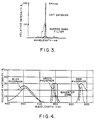
- Fig. 3 is a graph illustrating the light transmission characteristics of a typical monochrome filter.
- Fig. 4 is a graph illustrating the desired bandpass characteristics of an optimum color filter.
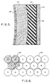
- Fig. 5 is an enlarged sectional view of a portion of the faceplate of the tube shown in Fig. 1 embodying the invention.
- Fig. 6 is a diagrammatic representation of the structure of the present invention, showing a portion of the screen of the tube of Fig. 1 in plan view.
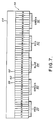
- Fig. 7 is an enlarged view in cross-section of an optical filter as in Fig. 6 emphasizing the fiber-optic filter elements, as in the present invention.
- Fig. 1 is a view showing a cathode ray display tube 10 or other luminescent display device. Electrical terminals 12 project longitudinally from a vacuum sealed envelope 14 including a cylindical neck portion 16, a viewing of faceplate face 18, and a transition section 20 joining the latter two elements.
- the display tube 10 may also include the usual internal elements (not shown) in the form of a cathode for emitting an electron beam, an anode, an electron beam deflecting structure, and a phosphor layer 22 affixed to the inner surface of the faceplate 18.
- Figures 1 and 2 refer to a structure in which a contrast enhancement filter 24 is affixed to the outer surface of the faceplate 18. While this illustrates a bonded filter, this structure is to be considered exemplary and not limiting. The objective of the configuration is to provide clearly to the viewer an undisturbed view of images formed by the electron beam on the cathode ray phosphor screen within the faceplate 18 under a wide range of ambient viewing conditions.
- Fig. 2 shows a light beam 30 emitted by the phosphor screen 22 as it passes through the faceplate 18, bonding layer 32, and contrast filter 24.
- ambient light rays 34 falling on the phosphor layer 22 will seriously interfere with the visibility of the light image produced by phosphor layer 22 by producing reflected rays 36.
- ambient light is considerably reduced with respect to the emitted light beams 30 by means of neutral density filtering which is achieved within the contrast filter 24. This filter effect occurs since the direct ray 30 is attenuated only once in its passage through filter 24, while the incident ray 34 must pass twice through the filter, thus incurring a higher degree of attenuation.
- the filter may be bonded to the faceplate 18 by a transparent adhesive layer 32 contained between the viewing face of the faceplate 18 and inner face of the filter 24. It is desirable that the materials of the cathode ray tube faceplate 18, the filter 24, and the adhesive layer 32 bonding together have substantially the same index of refraction, thereby eliminating undesirable reflections due to refractive mismatches at the interfaces.
- the light emitted by the phosphor 22 is desirably limited to a predetermined narrow region of the visible spectrum by appropriate selection of the phosphor material.
- a typical phosphor is the conventional P-43 phosphor having most of its energy concentrated in the green portion of the visible spectrum, having a wavelength of about 544 nanometers, as shown in Fig. 3. Accordingly, such CRT's can be more effectively filtered by a narrow-band filter which transmits the green wavelength spectrum, but absorbs all other incident wavelengths, than they can by a neutral density filter.
- Fig. 4 shows the emission spectra of a color cathode ray tube, having blue, green, and red components.
- the present invention provides a contrast enhancement filter for color displays (particularly shadow-mask CRT's) which performs in a manner similar to high performance narrow-band contrast enhancement filters presently used for monochrome displays.
- the present invention provides a filter transmission characteristic which closely matches the emission spectrum of the display, as shown in Fig. 4. To achieve this result with an absorbing dye which absorbs three appropriate narrow-band spectra has not proven feasible. Rather, this invention randomly disposes a plurality of individual dye materials within the filter, each of the dye materials having the proper spectral distribution for transmitting one and only one primary color.
- Fig. 5 shows an embodiment of the invention in which the filter is implemented in the form of a substantially transparent planar substrate 40 on which are located colored pigment dye areas 42.
- the composite filter plate may be adhered to the outer surface of the faceplate 18 by a transparent resin 32 or heat bonded in a furnace.
- Triads of phosphor elements 46 comprising phosphor layer 22 of the viewing screen are deposited in the inner surface of the faceplate 18.
- Another approach to fabrication of the absorbing filter is through application of absorbing filter materials, patterned using photolithographic techniques.
- One such technique is to provide a substrate of transparent material, coated with a photoresist material such as dichromate.
- the resist is patterned to provide a plurality of dots in a random pattern, corresponding to a statistical distribution of the primary red, green, and blue color elements.
- a dye having a color value corresponding to a selected primary color is applied to the patterned substrate, which is then coated with a transparent protective coating. This process is repeated with a second and third layer of material, each layer corresponding to a given one primary color, and the dot pattern being disposed so that dots in different layers do not overlap.
- Another process is adapted from a method used for fabricating color faceplates for liquid crystal displays.
- a single substrate is patterned with three groups of transparent, electrically conductive dots corresponding to the red, green, and blue primary colors desired in the finished color filter.
- Each group is comprised of a plurality of electrically interconnected dots which will be commonly colored.
- the groups are then selectively electroplated with an appropriately colored dye material.
- the filter plate may be designed to have substantial thickness, which offers certain advantages over the planar structure described above.
- One structure for implementing controlled thickness of the colored areas is to implant colored glass fibers.
- a filter structure of this type may be fabricated by modifying techniques well known in the art for fabricating fiber-optic collimating plates. While the prior art uses clear glass fibers, here colored fibers are used.
- a glass blank is doped with a colorant representing a primary color and drawn into a fiber.
- the fiber is then cut into sections and the lengths fused with fibers of other primary colors to form a fiber packet comprised of three primary colors, red, green, and blue, whose transmission spectra correspond to those desired to individually act as narrow band filters for each light-emitting phosphor dot.
- the packet is then drawn, fused, and the process repeated until the desired fiber diameter is reached.
- the resultant fused fibers are then distributed in a random pattern and fused to provide a cohesive R-G-B group of fibers.
- the fused fibers may be bonded to a transparent substrate and the resulting filter plate can be lapped to provide a predetermined fiber depth and predetermined thickness and flatness of the plate.
- the filter plate may be bonded to a faceplate or alternatively may be adapted for use as a faceplate 18 of a CRT, thus obviating the need for a separate faceplate and filter, thereby improving optical efficiency as well as simplifying construction, as compared to the laminated or composite structure.
- Fig. 7 shows in schematic form an enlarged cross-sectional view of such a fiber-optic faceplate.
- Red, green and blue phosphor dots 50, 52, 54 are sequentially disposed on the faceplate 56 which is comprised of a clear glass plate 64 on which are embedded a plurality of red, green and blue dyed fibers 58, 60, 62.
- Each fiber 58, 60, 62 absorbs light independently because of the spacial dispersion with respect to each other and with respect to the phosphor color dots.
- the viewing angle is determined by the fiber dimensions and the thickness of the plate. For good optical properties, both surfaces of the filter will be lapped to a desired flatness.
- Shadow mask CRT's generally have phosphor dots of greater than 0,114 mm (0.0045 inch) diameter. Therefore, filter elements having dimensions of 0,038 mm (0,0015 inch) smaller are suitable.
- the index of refraction of all fibers must be closely matched. If not matched, fibers of lower index will act as a cladding for fibers of higher index and produce an undesirable angular property in which the viewing angle of each color is different.
- the fiber-optic filter can be designed to have a specific acceptable angle, beyond which all light will be absorbed.
- This directional property depends on the length of the fiber with respect to the spacing between fibers of different colors. When the optical path through the filter requires passage through different colored fibers, all light will be absorbed.
- This property can be tailored to any acceptable angle by adjusting the length of the fiber, and can be useful when complete absorption of ambient light incident on the display from angles beyond a specified acceptance angle is desired.
- a fiber length equal to its diameter will provide a viewing angle of about 45 degrees, while a length of twice the diameter will limit the viewing angle to about 30 degrees.
- the present invention is applied to a color CRT display tube.
- a shadow mask CRT display it is well known to those skilled in the color CRT art that separate beams of energy are generated, usually from three separate electron guns, which beams are normally focused on a phosphor screen through a mask spaced from the interior surface of the faceplate, on which the phosphor is deposited.
- the screen is comprised of a multiplicity of minute openings through which the beam triad passes and then diverges to energize corresponding arrays of dot triads of red, green, and blue phosphors, resulting in red, green, and blue emissions from the face of the CRT.
- FIG. 6 shows a portion of such triad elements labelled R, G and B and corresponding to red, green, and blue phosphors, respectively.
- Other phosphor configurations such as non-circular regions, or even parallel stripes, may be employed.
- the colored pigmented dye area comprising a multiplicity of a given primary color value, superposed on a phosphor dot of the same color value, are indicated by reference 42.
- an absorption filter may be formed by photographing a master image, patterned with primary color areas of dimensions and separations as described above.
- the method of manufacture is to expose a photographic emulsion with the color pattern formed by the master image and to develop the latent image to form a color transparency whose primary color areas overlay the corresponding light-responsive display elements of a color display.
- the resultant transparency may be reduced or enlarged to suit the display face of a variety of display devices, and used as the absorption filter described above.
- cathode ray tubes having phosphorescent light-emitting elements this is not to be considered limiting, as the invention is applicable to any device employing light-responsive elements, which may be phosphorescent or of variable transmissibility, such as liquid-crystal elements.
- light-responsive elements which may be phosphorescent or of variable transmissibility, such as liquid-crystal elements.
- the disclosed embodiments of the invention have primarily described absorptive filter material located on a substrate which is subsequently attached to the front surface of a light emitting or transmitting color display, it is understood that the substrate may be the front plate of the display itself.
Landscapes
- Physics & Mathematics (AREA)
- General Physics & Mathematics (AREA)
- Optics & Photonics (AREA)
- Spectroscopy & Molecular Physics (AREA)
- Vessels, Lead-In Wires, Accessory Apparatuses For Cathode-Ray Tubes (AREA)
- Optical Filters (AREA)
- Devices For Indicating Variable Information By Combining Individual Elements (AREA)
- Liquid Crystal (AREA)
Abstract
Description
- The invention relates to an optical filter for contrast enhancement of a colour display according to the first part of claim 1. Such a filter is known from DE-U-8 512 243. The invention relates also to methods of making such filters.
- The invention pertains generally to contrast enhancement filters for viewing color displays, and more particularly to absorption filters providing improved viewability under conditions of high ambient light levels.
- When utilizing many displays such as cathode ray tube displays in high brightness ambient conditions, the information on the display becomes difficult to read due to reflections from the viewing screen. In such high ambients, reflected light from the viewing surface can exceed the internal light generated by the display itself, thereby resulting in a sufficient loss of contrast to wash out the presented information.
- One known prior art type of filter uses neutral density filtration. This has been achieved by providing colloidal suspensions such as silver in the glass composition of the faceplate or the implosion panel, or a colloidal graphite suspension within an adhesive material used to bond the implosion panel to the faceplate, as in U.S. Patent 3,879,627. This type of filter transmits a fraction of the light passing through it, which fraction is independent of the color emissions (i.e., wavelength ). Since the light from the display passes through the filter once, while ambient light reflected from the display must pass through the filter twice, the ratio of display brightness to ambient background brightness is thereby enhanced.
- When exposed to high brightness ambient lighting conditions, such as bright sunlight. the attenuation of transmitted light by a neutral density filter that is required to provide a satisfactory contrast ratio is so high that the resulting display brightness is too low to be acceptable. Another approach is selective filtration, obtained, for example, by the use of colored glass for either the tube faceplate or the implosion panel, or by adding colorants to the bonding material between the faceplate and the implosion panel. Such an approach is useful for a monochrome display, where the absorption characteristics of the filter may be formulated to provide a narrow band of transmission at the primary display wavelength. As with the neutral density filter, contrast is enhanced by the greater losses suffered by the ambient light in its reflected passage through the filter, as against a single passage through the filter of internally produced display light of monochromatic wavelength. However, at other wavelengths, the narrow band filter absorbs substantially all the ambient light. Therefore the contrast ratio, defined herein as the ratio of display brightness plus background brightness to background ambient brightness, is much greater with a narrow band filter than with a neutral density filter. However this approach requires a different colorant for each type of phosphor screen.
- Optical filters utilized by the prior art for color displays include absorption filters and thin film filters. An absorption filter is herein defined as one adapted to pass a narrow spectrum of light and substantially absorb all others. Such filters are relatively independent of the viewing angle. Color displays, such as are provided by color cathode ray tubes, typically emit three primary color wavelengths, such as red, green and blue, which may be combined to derive many colors. The ideal filter for a color CRT is comprised of three individually operative pass bands, each transmitting a narrow band of red, green or blue wavelengths emitted by the display. Materials are known which permit reasonably selective transmission of each of these wavelengths individually. However when such materials are either mixed in a single layer, or when individual filters for each wavelength are cascaded, such filters will mutually absorb wavelengths transmitted by the others. In the prior art selection of colorants and materials to provide selective transmission of multiple colors has been hampered by the co-existent requirements that each constituent element must transmit a predetermined narrow band of primary color wavelengths, yet not unduly absorb another wavelength band. Satisfactory materials with the precise desired transmission and absorption characteristics have not been found. The best of such prior art filters, as commonly used in aircraft for color CRT displays, has far from the ideal absorption spectrum.
- A further prior art approach that does not rely on absorbing materials to produce the desired transmission characteristics uses complex multilayer optical thin films or holograms. The effectiveness of these types of filters is reduced by a strong angular dependence inherent in the filter. The transmittance and reflectance properties are determined by interference phenomena which depend on optical path length which in turn depends on the viewing angle. Therefore, these filters are appropriate only in systems whose viewing angle is tightly constrained.
- Yet another approach to improve contrast is simply to increase the brightness level of the displayed information. However, thermal and longevity limitations preclude increasing brightness in conventional raster color displays to levels that are readable in daylight. A substantial increase in brightness can be obtained by operation in a vector (or stroke) writing mode. Vector writing has the disadvantage of being less efficient in terms of power consumption and the type of information which can be displayed.
- From DE-U-85 12 243 an optical filter for contrast enhancement of a color display is known where color phosphor dots of the screen are overlaid by filter areas which have a smaller diameter than the phosphor dots. Every dot of a certain color has a corresponding filter area of the same color.
- GB-A-2 178 226 shows a similar filter where a fiber optic faceplate is used to separate the color phosphor dot groups from a corresponding distribution of filter dot groups.
- Those known optical filters tend to generate Moiré effects.
- The present invention overcomes the disadvantages of the prior art by providing a contrast enhancement filter according to claim 1 containing absorptive dye colorants which are spatially separated. Each color element can therefore act independently of the others. Since absorption effects are used rather than interference effects, the filter performance is essentially independent of angle of vision over a broad viewing range.
- The dependent claims describe particular embodiments of the invention. Such contrast enhancement filters can be manufactured by the methods according to claims 8 and 11.
- The invention comprises a planar substrate in which are defined a plurality of spaced areas of a predetermined color transmissibility. Each area is selectively dyed to transmit a narrow band color spectrum and substantially to absorb other color wavelengths. The colored areas are patterned so that a plurality of such areas comprising at least one primary color wavelength overlay each of the discrete light-responsive elements of a corresponding primary color wavelength of a color display, wherein each of said elements is adapted for emitting or transmitting light in a predetermined primary color wavelength.
- In a preferred embodiment, particles of fiber-optic material are selectively dyed to provide a narrow-band transmission of the primary colors, and dispersed within the base material of a planar substrate. The fiber-optic particles are selected to have identical indices of refraction to avoid unwanted collimating of the display information, sized so that a plurality of fibers of a given primary absorption characteristic are overlaid on a corresponding primary emission color dot. According to the present invention, the particles will be randonly disposed over the color dots to avoid Moire' effects.
- Fig. 1 is an elevation view partly in vertical section of a cathode ray tube.
- Fig. 2 is an enlarged sectional view of a portion of the faceplate of the tube shown in Fig. 1, illustrating a contrast enhancement filter.
- Fig. 3 is a graph illustrating the light transmission characteristics of a typical monochrome filter.
- Fig. 4 is a graph illustrating the desired bandpass characteristics of an optimum color filter.
- Fig. 5 is an enlarged sectional view of a portion of the faceplate of the tube shown in Fig. 1 embodying the invention.
- Fig. 6 is a diagrammatic representation of the structure of the present invention, showing a portion of the screen of the tube of Fig. 1 in plan view.
- Fig. 7 is an enlarged view in cross-section of an optical filter as in Fig. 6 emphasizing the fiber-optic filter elements, as in the present invention.
- Fig. 1 is a view showing a cathode
ray display tube 10 or other luminescent display device.Electrical terminals 12 project longitudinally from a vacuum sealedenvelope 14 including acylindical neck portion 16, a viewing offaceplate face 18, and atransition section 20 joining the latter two elements. Thedisplay tube 10 may also include the usual internal elements (not shown) in the form of a cathode for emitting an electron beam, an anode, an electron beam deflecting structure, and aphosphor layer 22 affixed to the inner surface of thefaceplate 18. - Figures 1 and 2 refer to a structure in which a
contrast enhancement filter 24 is affixed to the outer surface of thefaceplate 18. While this illustrates a bonded filter, this structure is to be considered exemplary and not limiting. The objective of the configuration is to provide clearly to the viewer an undisturbed view of images formed by the electron beam on the cathode ray phosphor screen within thefaceplate 18 under a wide range of ambient viewing conditions. - Fig. 2 shows a
light beam 30 emitted by thephosphor screen 22 as it passes through thefaceplate 18,bonding layer 32, andcontrast filter 24. In a normal tube structure of the character described above, it has been found that ambient light rays 34 falling on thephosphor layer 22 will seriously interfere with the visibility of the light image produced byphosphor layer 22 by producing reflectedrays 36. In accordance with the prior art, ambient light is considerably reduced with respect to the emitted light beams 30 by means of neutral density filtering which is achieved within thecontrast filter 24. This filter effect occurs since thedirect ray 30 is attenuated only once in its passage throughfilter 24, while theincident ray 34 must pass twice through the filter, thus incurring a higher degree of attenuation. The filter may be bonded to thefaceplate 18 by a transparentadhesive layer 32 contained between the viewing face of thefaceplate 18 and inner face of thefilter 24. It is desirable that the materials of the cathoderay tube faceplate 18, thefilter 24, and theadhesive layer 32 bonding together have substantially the same index of refraction, thereby eliminating undesirable reflections due to refractive mismatches at the interfaces. - In some cathode ray tubes (CRT's) the light emitted by the
phosphor 22 is desirably limited to a predetermined narrow region of the visible spectrum by appropriate selection of the phosphor material. A typical phosphor is the conventional P-43 phosphor having most of its energy concentrated in the green portion of the visible spectrum, having a wavelength of about 544 nanometers, as shown in Fig. 3. Accordingly, such CRT's can be more effectively filtered by a narrow-band filter which transmits the green wavelength spectrum, but absorbs all other incident wavelengths, than they can by a neutral density filter. - Fig. 4 shows the emission spectra of a color cathode ray tube, having blue, green, and red components. A filter with three pass bands, each transmitting only those red, green and blue wavelengths emitted by the display, is desired to effectively improve the contrast ratio. The present invention provides a contrast enhancement filter for color displays (particularly shadow-mask CRT's) which performs in a manner similar to high performance narrow-band contrast enhancement filters presently used for monochrome displays. In particular, the present invention provides a filter transmission characteristic which closely matches the emission spectrum of the display, as shown in Fig. 4. To achieve this result with an absorbing dye which absorbs three appropriate narrow-band spectra has not proven feasible. Rather, this invention randomly disposes a plurality of individual dye materials within the filter, each of the dye materials having the proper spectral distribution for transmitting one and only one primary color.
- Fig. 5 shows an embodiment of the invention in which the filter is implemented in the form of a substantially transparent
planar substrate 40 on which are located coloredpigment dye areas 42. The composite filter plate may be adhered to the outer surface of thefaceplate 18 by atransparent resin 32 or heat bonded in a furnace. Triads ofphosphor elements 46 comprisingphosphor layer 22 of the viewing screen are deposited in the inner surface of thefaceplate 18. - Another approach to fabrication of the absorbing filter is through application of absorbing filter materials, patterned using photolithographic techniques. One such technique is to provide a substrate of transparent material, coated with a photoresist material such as dichromate. The resist is patterned to provide a plurality of dots in a random pattern, corresponding to a statistical distribution of the primary red, green, and blue color elements. A dye having a color value corresponding to a selected primary color is applied to the patterned substrate, which is then coated with a transparent protective coating. This process is repeated with a second and third layer of material, each layer corresponding to a given one primary color, and the dot pattern being disposed so that dots in different layers do not overlap.
- Another process is adapted from a method used for fabricating color faceplates for liquid crystal displays. Here a single substrate is patterned with three groups of transparent, electrically conductive dots corresponding to the red, green, and blue primary colors desired in the finished color filter. Each group is comprised of a plurality of electrically interconnected dots which will be commonly colored. The groups are then selectively electroplated with an appropriately colored dye material.
- In a further embodiment as shown in Fig. 7, the filter plate may be designed to have substantial thickness, which offers certain advantages over the planar structure described above. One structure for implementing controlled thickness of the colored areas is to implant colored glass fibers. A filter structure of this type may be fabricated by modifying techniques well known in the art for fabricating fiber-optic collimating plates. While the prior art uses clear glass fibers, here colored fibers are used. A glass blank is doped with a colorant representing a primary color and drawn into a fiber. The fiber is then cut into sections and the lengths fused with fibers of other primary colors to form a fiber packet comprised of three primary colors, red, green, and blue, whose transmission spectra correspond to those desired to individually act as narrow band filters for each light-emitting phosphor dot. The packet is then drawn, fused, and the process repeated until the desired fiber diameter is reached. The resultant fused fibers are then distributed in a random pattern and fused to provide a cohesive R-G-B group of fibers. The fused fibers may be bonded to a transparent substrate and the resulting filter plate can be lapped to provide a predetermined fiber depth and predetermined thickness and flatness of the plate. The filter plate may be bonded to a faceplate or alternatively may be adapted for use as a
faceplate 18 of a CRT, thus obviating the need for a separate faceplate and filter, thereby improving optical efficiency as well as simplifying construction, as compared to the laminated or composite structure. - Fig. 7 shows in schematic form an enlarged cross-sectional view of such a fiber-optic faceplate. Red, green and
blue phosphor dots faceplate 56 which is comprised of aclear glass plate 64 on which are embedded a plurality of red, green and bluedyed fibers fiber - In order to minimize Moire' effects, it is preferable to randomize the locations of the color-dyed areas or
fiber particles - When colored glass fibers are used, the index of refraction of all fibers must be closely matched. If not matched, fibers of lower index will act as a cladding for fibers of higher index and produce an undesirable angular property in which the viewing angle of each color is different.
- Advantageously, the fiber-optic filter can be designed to have a specific acceptable angle, beyond which all light will be absorbed. This directional property depends on the length of the fiber with respect to the spacing between fibers of different colors. When the optical path through the filter requires passage through different colored fibers, all light will be absorbed. This property can be tailored to any acceptable angle by adjusting the length of the fiber, and can be useful when complete absorption of ambient light incident on the display from angles beyond a specified acceptance angle is desired. Thus, for example, a fiber length equal to its diameter will provide a viewing angle of about 45 degrees, while a length of twice the diameter will limit the viewing angle to about 30 degrees.
- In a preferred embodiment, the present invention is applied to a color CRT display tube. For a shadow mask CRT display it is well known to those skilled in the color CRT art that separate beams of energy are generated, usually from three separate electron guns, which beams are normally focused on a phosphor screen through a mask spaced from the interior surface of the faceplate, on which the phosphor is deposited. For example, in a shadow mask structure the screen is comprised of a multiplicity of minute openings through which the beam triad passes and then diverges to energize corresponding arrays of dot triads of red, green, and blue phosphors, resulting in red, green, and blue emissions from the face of the CRT. Fig. 6 shows a portion of such triad elements labelled R, G and B and corresponding to red, green, and blue phosphors, respectively. Other phosphor configurations, such as non-circular regions, or even parallel stripes, may be employed. The colored pigmented dye area, comprising a multiplicity of a given primary color value, superposed on a phosphor dot of the same color value, are indicated by
reference 42. - In a further embodiment, an absorption filter may be formed by photographing a master image, patterned with primary color areas of dimensions and separations as described above. The method of manufacture is to expose a photographic emulsion with the color pattern formed by the master image and to develop the latent image to form a color transparency whose primary color areas overlay the corresponding light-responsive display elements of a color display. The resultant transparency may be reduced or enlarged to suit the display face of a variety of display devices, and used as the absorption filter described above.
- While the examples given herein have primarily exemplified cathode ray tubes having phosphorescent light-emitting elements, this is not to be considered limiting, as the invention is applicable to any device employing light-responsive elements, which may be phosphorescent or of variable transmissibility, such as liquid-crystal elements. As an example, while the disclosed embodiments of the invention have primarily described absorptive filter material located on a substrate which is subsequently attached to the front surface of a light emitting or transmitting color display, it is understood that the substrate may be the front plate of the display itself.
- While the invention has been described in its preferred embodiments, it is to be understood that the words which have been used are words of description rather than limitation and that changes may be made within the purview of the appended claims without departing from the true scope of the appended claims.
Claims (14)
- An optical filter (24) for contrast enhancement of a color display (10), said display comprising a light-responsive layer having a plurality of discrete elements (46), each of said elements adapted for emitting or transmitting light in a predetermined primary color wavelength, comprising:
an optically transparent substrate (40),
a plurality of areas (42) of a predetermined color transmissibility disposed on said substrate and spaced there between, each of said areas selectively dyed to transmit a narrow band color spectrum corresponding to at least one said predetermined primary color wavelength of said discrete elements, and substantially to absorb color wavelengths other than said one primary color wavelength,
said areas (42) patterned to overlay ones of said discrete elements (46), a plurality of areas comprising at least one primary color wavelength overlaying each of said discrete elements, characterized in that,
said plurality of said areas of a predetermined color transmissibility have a distribution randomly disposed over said discrete elements of said light-responsive layer, with said discrete elements having a first predetermined diameter and said color areas having a second predetermined diameter substantially less than said first predetermined diameter. - Filter according to claim 1, characterized in that said discrete elements have a diameter of at least 0,114 mm (0.0045 inch), and said color areas have a diameter not exceeding 0,038 mm (0.0015 inch).
- Filter according to claim 1, characterized by :
a plurality of fibers (58, 60, 62) oriented within a face plate (56) such that the fibers are parallel to each other and perpendicular to the surface of said face plate having substantially identical indices of refraction, each of said fibers selectively dyed to provide a transmission color spectrum corresponding to one of said primary color wavelengths,
said fibers patterned to overlay said discrete elements (46), a plurality of said fibers of a predetermined color transmissibility overlaying each of said discrete elements of corresponding color emission, and
means (32) for bonding said fibers to a glass plate (64). - Filter according to claim 3, characterized in that said fibers (58, 60, 62) have a predetermined length and a predetermined spacing between fibers of a different color transmissibility, the ratio of said length to spacing defining an optical acceptance angle wherein ambient light impinging on said optical filter outside of said angle is substantially totally absorbed.
- Filter according to claim 4, characterized in that said fibers (58, 60, 62) have a first predetermined diameter and said discrete elements have a second predetermined diameter, the ratio of said second to said first diameters being 3:1.
- Filter according to claim 3, further characterized by :
a color cathode ray tube (10) in front of which said faceplate (56) is arranged. - Filter according to claim 6, further comprising:
an optically transparent resin (32) for bonding said filter (24) to a faceplate (18) of said cathode ray tube (10). - A method of making a contrast enhancement filter according to one of claims 1 to 7 for use with a color display device having a display face including a plurality of light-responsive discrete elements (46) having a first predetermined diameter for providing first, second, and third primary colors comprising the steps of:
providing a substrate to provide a first plurality of color areas (42) of a second predetermined diameter which is substantially less than said first diameter, said color areas representative of a first plurality of primary color transmission elements corresponding to one of said primary colors,
applying a first dye corresponding to said one of said primary colors to said plurality of said color areas,
applying a protective transparent coating to said color areas substrate,
patterning said substrate to provide at least a second plurality of color areas of said second predetermined diameter spaced between said first plurality of color areas, said second plurality of color areas representative of a second plurality of primary color transmission elements corresponding to a second one of said primary colors, applying a second dye corresponding to said second one of said primary colors to said second plurality of color areas, and
applying a protective transparent coating to said second substrate over said second color areas, wherein said first and second or eventually third plurality of color areas is disposed in a random pattern corresponding to a statistical distribution of said first, second and third primary colors of said light-responsive elements. - A method of making a contrast enhancement filter according to claim 8, further comprising:
patterning said substrate to provide a third plurality of color areas of said second predetermined diameter spaced between said first and second pluralities of color areas, said third plurality of color areas representative of a third plurality of primary color transmission elements corresponding to a third one of said primary colors,
applying a third dye corresponding to said third one of said primary colors to said third plurality of color areas, and
applying a protective transparent coating to said substrate over said third color areas, wherein said first, second and third plurality of color areas is disposed in a random pattern corresponding to a statistical distribution of said first, second and third primary colors of said light-responsive elements. - A method according to claim 9, characterized in that said substrate comprises first, second, and third substrates for receiving ones of said primary color areas, said substrate comprising a photosensitive gelatin, and said process of patterning includes exposing said gelatin to a source of light and developing a resultant latent image.
- A method of making a contrast enhancement filter according to one of claims 1 to 7, characterized by the steps of:
providing a substrate having an electrically conductive surface,
patterning said electrically conductive surface to provide groups of a plurality of optically transparent areas, each said plurality comprised of electrically connected areas which will be commonly colored with a predetermined primary color value to form said color areas, selectively electro-depositing an absorbent dye to each of said group of areas disposed in accordance with a predetermined distribution of red, green, and blue color elements corresponding to the emitting or transmitting light elements of a color display, whereat said color areas are arranged in a random pattern and said color areas have a substantially smaller diameter than the color elements. - A method of making a contrast enhancement filter for color displays according to one ofclaims 1 to 7, characterized by the steps of:
defining an image to be photographed, patterned with a plurality of areas defining primary color elements, said elements spatially disposed to overlay the light-responsive elements of a color display, a plurality of color elements of at least one primary color randomly disposed over areas corresponding to each of said light-responsive elements, photographing said image pattern, and
developing a latent image to replicate said primary color elements. - A method according to claim 12, further characterized by the step of photographically reducing or enlarging said replicated image to conform to the size and disposition of the light-responsive elements of a given color display, so that a single master image pattern may be utilized for a plurality of color displays of varying element size, shape, and spatial disposition.
- A method according to claim 13, further characterized by the steps of:
patterning said image to be photographed with red color elements,
patterning said image to be photographed with blue color elements, and
patterning said image to be photographed with green color elements.
Applications Claiming Priority (3)
| Application Number | Priority Date | Filing Date | Title |
|---|---|---|---|
| US347107 | 1989-05-03 | ||
| US07/347,107 US5121030A (en) | 1989-05-03 | 1989-05-03 | Absorption filters for chlor display devices |
| PCT/US1990/002248 WO1990013906A1 (en) | 1989-05-03 | 1990-04-26 | Absorption filter for color display devices |
Publications (3)
| Publication Number | Publication Date |
|---|---|
| EP0471007A1 EP0471007A1 (en) | 1992-02-19 |
| EP0471007A4 EP0471007A4 (en) | 1992-03-18 |
| EP0471007B1 true EP0471007B1 (en) | 1995-08-30 |
Family
ID=23362352
Family Applications (1)
| Application Number | Title | Priority Date | Filing Date |
|---|---|---|---|
| EP90907670A Expired - Lifetime EP0471007B1 (en) | 1989-05-03 | 1990-04-26 | Absorption filter for color display devices |
Country Status (7)
| Country | Link |
|---|---|
| US (1) | US5121030A (en) |
| EP (1) | EP0471007B1 (en) |
| JP (1) | JPH04504924A (en) |
| KR (1) | KR920700465A (en) |
| CA (1) | CA2032166A1 (en) |
| DE (1) | DE69022048T2 (en) |
| WO (1) | WO1990013906A1 (en) |
Families Citing this family (54)
| Publication number | Priority date | Publication date | Assignee | Title |
|---|---|---|---|---|
| US5247600A (en) * | 1990-01-03 | 1993-09-21 | Williams Charles M | Fiber optic data/graphic display screen |
| JPH07120515B2 (en) * | 1990-09-27 | 1995-12-20 | 三菱電機株式会社 | Color cathode ray tube with light selective absorption film |
| JPH04306630A (en) * | 1991-04-04 | 1992-10-29 | Matsushita Electric Ind Co Ltd | Projection type tv device |
| US6511187B1 (en) | 1992-02-20 | 2003-01-28 | Kopin Corporation | Method of fabricating a matrix display system |
| US5521759A (en) * | 1993-06-07 | 1996-05-28 | National Research Council Of Canada | Optical filters for suppressing unwanted reflections |
| US5569977A (en) * | 1994-03-08 | 1996-10-29 | Philips Electronics North America Corporation | Cathode ray tube with UV-reflective filter and UV-excitable phosphor |
| GB9413883D0 (en) * | 1994-07-09 | 1994-08-31 | Philips Electronics Uk Ltd | Colour liquid crystal projection display systems |
| DE69503468T2 (en) * | 1994-11-21 | 1999-03-04 | Philips Electronics N.V., Eindhoven | IMAGE DISPLAY DEVICE WITH AN AUTOMATIC, SELECTIVELY TRANSLUCENT COATING |
| EP0873538A4 (en) | 1995-04-11 | 2005-02-02 | Litton Systems Inc | Daylight readable liquid crystal display |
| TW300310B (en) * | 1995-05-10 | 1997-03-11 | Toshiba Co Ltd | |
| DE69620516T2 (en) * | 1995-07-24 | 2002-11-07 | Kabushiki Kaisha Toshiba, Kawasaki | Color picture tube |
| USRE37750E1 (en) | 1995-07-24 | 2002-06-18 | Kabushiki Kaisha Toshiba | CRT having color filter with a special green filter |
| US5834122A (en) * | 1996-11-25 | 1998-11-10 | Hoechst Celanese Corp. | Spectrally tuned multiple bandpass filters for video displays |
| WO1998057201A1 (en) * | 1997-06-09 | 1998-12-17 | Hoechst Celanese Corporation | Spectrally tuned multiple bandpass filters for video displays |
| WO1999001883A1 (en) * | 1997-07-01 | 1999-01-14 | Hna Holdings, Inc. | Video display substrates with built-in spectroscopically tuned multi-bandpass filters |
| US20020005509A1 (en) * | 1999-01-21 | 2002-01-17 | Chia-Chi Teng | Dye combinations for image enhancement filters for color video displays |
| US6229252B1 (en) * | 1999-01-21 | 2001-05-08 | Asahi Glass Company, Limited | Dye combinations for multiple bandpass filters for video displays |
| JP3576032B2 (en) * | 1999-03-31 | 2004-10-13 | 富士通株式会社 | Gas discharge display |
| US6717626B1 (en) * | 2000-05-08 | 2004-04-06 | Mitsubishi Digital Electronics America, Inc. | High contrast projection television shield |
| JP3922177B2 (en) * | 2002-02-12 | 2007-05-30 | セイコーエプソン株式会社 | Film forming method, film forming apparatus, droplet discharge apparatus, color filter manufacturing method, display apparatus manufacturing method |
| US6960873B2 (en) * | 2002-08-19 | 2005-11-01 | Thomson Licensing | CRT having internal neutral density filter field of use |
| AU2003219487A1 (en) * | 2003-04-02 | 2004-10-25 | Magink Display Technologies Ltd. | Psychophysical perception enhancement |
| TWI273285B (en) * | 2005-12-23 | 2007-02-11 | Wintek Corp | Color filter having capability of changing light-color |
| ES2281301B1 (en) | 2006-10-16 | 2008-07-16 | Universidad Complutense De Madrid | LIGHTING DEVICE WITH THERAPEUTIC AND PROFILACTIC FILTER FOR HEALTHY EYES, PSEUDO-AFAQUICOS AND / OR IN NEURODEGENERATION PROCESS. |
| US7914177B2 (en) * | 2006-11-07 | 2011-03-29 | Universidad Complutense De Madrid | Prophylaxic/therapeutic vehicle filter component for healthy eyes, pseudoaphakic eyes or eyes suffering neurodegeneration |
| US7832903B2 (en) * | 2006-11-07 | 2010-11-16 | Universidad Complutense De Madrid | Illumination system fitted with a therapeutic/prophylactic filter for healthy eyes, pseudoaphakic eyes or eyes suffering neurodegeneration |
| ES2281303B1 (en) | 2006-12-04 | 2008-07-16 | Universidad Complutense De Madrid | PREVENTION COMPONENT FOR HEALTHY EYES AND THERAPY AND PROFILAXIS FOR PSEUDO-AFAQUIC EYES AND / OR IN PROCESS OF VEHICLE NEURODEGENERATION. |
| ES2289957B1 (en) | 2007-02-07 | 2008-12-01 | Universidad Complutense De Madrid | LIGHTING SOURCE WITH REDUCED ISSUANCE OF SHORT WAVE LENGTHS FOR EYE PROTECTION. |
| ES2296552B1 (en) | 2007-06-01 | 2009-08-25 | Universidad Complutense De Madrid | ELEMENT OF PREVENTION ON TRANSPARENT SURFACES OF BUILDINGS FOR THE PROTECTION AND THERAPY OF EYES. |
| ES2303484B2 (en) | 2007-10-15 | 2010-03-08 | Universidad Complutense De Madrid | COVERAGE, COATING OR DISPLAY MATERIAL FOR EYE PROTECTION AND THERAPY AGAINST THE EFFECTS OF BLUE LIGHT. |
| JP4538527B1 (en) * | 2009-03-19 | 2010-09-08 | イクス株式会社 | Information processing apparatus and method, and program |
| WO2011044341A1 (en) | 2009-10-08 | 2011-04-14 | Summalux, Llc | Led lighting system |
| EP3567416A1 (en) | 2009-10-12 | 2019-11-13 | The Trustees of Columbia University in the City of New York | Photonic crystal spectrometer |
| US8770749B2 (en) | 2010-04-15 | 2014-07-08 | Oakley, Inc. | Eyewear with chroma enhancement |
| CN102650755B (en) * | 2011-05-24 | 2014-09-03 | 京东方科技集团股份有限公司 | Color diaphragm base plate, color filter and manufacturing method of color filter |
| AU2012336204B2 (en) | 2011-10-20 | 2016-08-25 | Oakley, Inc. | Eyewear with chroma enhancement |
| WO2013169987A1 (en) | 2012-05-10 | 2013-11-14 | Oakley, Inc. | Eyewear with laminated functional layers |
| EP2891019B1 (en) | 2012-08-28 | 2020-03-04 | Delos Living, LLC | Systems and methods for enhancing wellness associated with habitable environments |
| US9575335B1 (en) | 2014-01-10 | 2017-02-21 | Oakley, Inc. | Eyewear with chroma enhancement for specific activities |
| EP3754588B1 (en) | 2014-02-28 | 2023-08-16 | Delos Living LLC | Systems, methods, and articles for enhancing wellness associated with habitable environments |
| US10871661B2 (en) | 2014-05-23 | 2020-12-22 | Oakley, Inc. | Eyewear and lenses with multiple molded lens components |
| WO2016077431A2 (en) | 2014-11-13 | 2016-05-19 | Oakley, Inc. | Variable light attenuation eyewear with color enhancement |
| AU2016202287B2 (en) | 2015-01-13 | 2021-04-01 | Delos Living Llc | Systems, methods and articles for monitoring and enhancing human wellness |
| US9905022B1 (en) | 2015-01-16 | 2018-02-27 | Oakley, Inc. | Electronic display for demonstrating eyewear functionality |
| US10656013B2 (en) | 2015-09-29 | 2020-05-19 | Chromation Inc. | Nanostructure based article, optical sensor and analytical instrument and method of forming same |
| EP3455597B1 (en) | 2016-05-10 | 2024-11-27 | Chromation Inc. | Integration of optical components within a folded optical path |
| US11338107B2 (en) | 2016-08-24 | 2022-05-24 | Delos Living Llc | Systems, methods and articles for enhancing wellness associated with habitable environments |
| WO2019046580A1 (en) | 2017-08-30 | 2019-03-07 | Delos Living Llc | Systems, methods and articles for assessing and/or improving health and well-being |
| US12124116B2 (en) | 2017-10-20 | 2024-10-22 | Luxottica S.R.L. | Eyewear with variable transmission lens |
| US11112622B2 (en) | 2018-02-01 | 2021-09-07 | Luxottica S.R.L. | Eyewear and lenses with multiple molded lens components |
| US11649977B2 (en) | 2018-09-14 | 2023-05-16 | Delos Living Llc | Systems and methods for air remediation |
| WO2020176503A1 (en) | 2019-02-26 | 2020-09-03 | Delos Living Llc | Method and apparatus for lighting in an office environment |
| US11898898B2 (en) | 2019-03-25 | 2024-02-13 | Delos Living Llc | Systems and methods for acoustic monitoring |
| WO2022076438A1 (en) | 2020-10-06 | 2022-04-14 | Chromation Inc. | Systems and methods to redistribute field of view in spectroscopy |
Family Cites Families (20)
| Publication number | Priority date | Publication date | Assignee | Title |
|---|---|---|---|---|
| US2618759A (en) * | 1952-01-15 | 1952-11-18 | Walter Mellott | Viewing screen for color television receivers |
| US3210585A (en) * | 1960-03-01 | 1965-10-05 | Gen Dynamics Corp | Horizontal color stripe tube with interlacing scan and beam velocity modulation |
| US3863093A (en) * | 1969-01-30 | 1975-01-28 | Itt | Multicolor direct view device |
| US3638060A (en) * | 1970-05-25 | 1972-01-25 | Gte Laboratories Inc | Phosphor display screen and filter including platinum and manganese chloride derivatives of tetraphenylporphin |
| US3814618A (en) * | 1971-10-15 | 1974-06-04 | Kaiser Glass Fiber Corp | Production of colored coated glass fibers |
| JPS49130669A (en) * | 1973-04-16 | 1974-12-14 | ||
| US4135112A (en) * | 1973-11-02 | 1979-01-16 | Gte Sylvania Incorporated | Color cathode ray tube screen structure providing improved contrast |
| JPS54148473A (en) * | 1978-05-15 | 1979-11-20 | Nec Corp | Cathode-ray tube |
| US4386143A (en) * | 1978-06-28 | 1983-05-31 | Masamichi Sato | Multicolor optical filters and process for producing the same |
| US4185228A (en) * | 1978-10-19 | 1980-01-22 | Gte Laboratories Incorporated | Electrodeless light source with self-contained excitation source |
| CA1128107A (en) * | 1978-11-06 | 1982-07-20 | American Optical Corporation | Color image intensifier |
| US4354739A (en) * | 1980-09-03 | 1982-10-19 | Optical Coating Laboratory, Inc. | Color absorption-type filter and method of making |
| US4591232A (en) * | 1983-06-03 | 1986-05-27 | Incom, Inc. | Optical display screen utilizing light-absorbing fibers |
| JPS6023830A (en) * | 1983-07-19 | 1985-02-06 | Seiko Instr & Electronics Ltd | Preparation of multicolor display device |
| JPS60179703A (en) * | 1984-02-28 | 1985-09-13 | Seiko Instr & Electronics Ltd | Manufacture of multicolored display device |
| US4701789A (en) * | 1985-03-13 | 1987-10-20 | Rank Electronic Tubes Limited | Cathode ray tube |
| DE8512243U1 (en) * | 1985-04-25 | 1986-10-23 | Klimsch & Co KG, 6000 Frankfurt | Optical filter |
| GB2178226A (en) * | 1985-06-12 | 1987-02-04 | Gec Avionics Limted | Cathode ray tubes |
| US4786148A (en) * | 1986-12-10 | 1988-11-22 | Canon Kabushiki Kaisha | Color filter having different primary color pigment densities, inter alia |
| JPH0721562B2 (en) * | 1987-05-14 | 1995-03-08 | 凸版印刷株式会社 | Color filter |
-
1989
- 1989-05-03 US US07/347,107 patent/US5121030A/en not_active Expired - Lifetime
-
1990
- 1990-04-26 JP JP2507514A patent/JPH04504924A/en active Pending
- 1990-04-26 CA CA002032166A patent/CA2032166A1/en not_active Abandoned
- 1990-04-26 WO PCT/US1990/002248 patent/WO1990013906A1/en not_active Ceased
- 1990-04-26 KR KR1019900702610A patent/KR920700465A/en not_active Ceased
- 1990-04-26 DE DE69022048T patent/DE69022048T2/en not_active Expired - Fee Related
- 1990-04-26 EP EP90907670A patent/EP0471007B1/en not_active Expired - Lifetime
Also Published As
| Publication number | Publication date |
|---|---|
| EP0471007A1 (en) | 1992-02-19 |
| US5121030A (en) | 1992-06-09 |
| KR920700465A (en) | 1992-02-19 |
| JPH04504924A (en) | 1992-08-27 |
| DE69022048T2 (en) | 1996-05-02 |
| DE69022048D1 (en) | 1995-10-05 |
| EP0471007A4 (en) | 1992-03-18 |
| CA2032166A1 (en) | 1990-11-04 |
| WO1990013906A1 (en) | 1990-11-15 |
Similar Documents
| Publication | Publication Date | Title |
|---|---|---|
| EP0471007B1 (en) | Absorption filter for color display devices | |
| US5233183A (en) | Color image intensifier device and method for producing same | |
| JP3147122B2 (en) | Method for manufacturing sheet-like member and transmission screen | |
| US4245242A (en) | Contrast enhancement of multicolor displays | |
| US6529322B1 (en) | High contrast front and rear viewing surfaces for projection displays | |
| EP0712148B1 (en) | Plasma display system | |
| US5648860A (en) | Projection type color liquid crystal optical apparatus | |
| US4663562A (en) | Contrast enhancement structure for color cathode ray tube | |
| US6751019B2 (en) | Ultrathin mesh optical panel and a method of making an ultrathin mesh optical panel | |
| JPH06102510A (en) | Two-light-path liquid-crystal light-bulb color display device using optical coupling lens array | |
| JP3065458B2 (en) | EL element | |
| JPS63186213A (en) | Display device | |
| JPS6155641B2 (en) | ||
| US4914510A (en) | Method for improving the white field uniformity of a projection color TV using CRTs having interference filters, projection color TV and CRTs resulting from the method | |
| US4454535A (en) | Color picture projection system | |
| EP0166372B1 (en) | Optical filter made of inorganic material for blue light | |
| US4741963A (en) | Optical filter made of inorganic material for green light | |
| US4027328A (en) | Catadioptrically coupled color television projection system | |
| US5559564A (en) | Cathode ray tube apparatus for projection TV system | |
| EP0369730B1 (en) | Color liquid crystal display | |
| GB2034513A (en) | Colour image intensifier | |
| JPH0792465A (en) | Transmissive color image display device | |
| GB2178226A (en) | Cathode ray tubes | |
| CA2016379C (en) | Three tube color projection system having at least one tube without an interference filter | |
| KR950010734B1 (en) | Projection type TV device |
Legal Events
| Date | Code | Title | Description |
|---|---|---|---|
| PUAI | Public reference made under article 153(3) epc to a published international application that has entered the european phase |
Free format text: ORIGINAL CODE: 0009012 |
|
| 17P | Request for examination filed |
Effective date: 19911030 |
|
| AK | Designated contracting states |
Kind code of ref document: A1 Designated state(s): DE FR GB |
|
| A4 | Supplementary search report drawn up and despatched |
Effective date: 19920127 |
|
| AK | Designated contracting states |
Kind code of ref document: A4 Designated state(s): DE FR GB |
|
| 17Q | First examination report despatched |
Effective date: 19940815 |
|
| GRAA | (expected) grant |
Free format text: ORIGINAL CODE: 0009210 |
|
| AK | Designated contracting states |
Kind code of ref document: B1 Designated state(s): DE FR GB |
|
| ET | Fr: translation filed | ||
| REF | Corresponds to: |
Ref document number: 69022048 Country of ref document: DE Date of ref document: 19951005 |
|
| PLBE | No opposition filed within time limit |
Free format text: ORIGINAL CODE: 0009261 |
|
| STAA | Information on the status of an ep patent application or granted ep patent |
Free format text: STATUS: NO OPPOSITION FILED WITHIN TIME LIMIT |
|
| 26N | No opposition filed | ||
| PGFP | Annual fee paid to national office [announced via postgrant information from national office to epo] |
Ref country code: GB Payment date: 20010313 Year of fee payment: 12 |
|
| PGFP | Annual fee paid to national office [announced via postgrant information from national office to epo] |
Ref country code: FR Payment date: 20010405 Year of fee payment: 12 |
|
| PGFP | Annual fee paid to national office [announced via postgrant information from national office to epo] |
Ref country code: DE Payment date: 20010430 Year of fee payment: 12 |
|
| REG | Reference to a national code |
Ref country code: GB Ref legal event code: IF02 |
|
| PG25 | Lapsed in a contracting state [announced via postgrant information from national office to epo] |
Ref country code: GB Free format text: LAPSE BECAUSE OF NON-PAYMENT OF DUE FEES Effective date: 20020426 |
|
| PG25 | Lapsed in a contracting state [announced via postgrant information from national office to epo] |
Ref country code: DE Free format text: LAPSE BECAUSE OF NON-PAYMENT OF DUE FEES Effective date: 20021101 |
|
| GBPC | Gb: european patent ceased through non-payment of renewal fee |
Effective date: 20020426 |
|
| PG25 | Lapsed in a contracting state [announced via postgrant information from national office to epo] |
Ref country code: FR Free format text: LAPSE BECAUSE OF NON-PAYMENT OF DUE FEES Effective date: 20021231 |
|
| REG | Reference to a national code |
Ref country code: FR Ref legal event code: ST |
|
| P01 | Opt-out of the competence of the unified patent court (upc) registered |
Effective date: 20230526 |